
Radio Technique
George M. Myers
Something About Switches: Some time ago, a friend called me with a problem. I agreed to look into it, and when I did it seemed that the problem was traceable to high resistance in a switch. Before I could tell him that such resistances are usually measured in 1/1000ths of an ohm and would be invisible on his multimeter, he started probing around in the circuit and said "AHA, you're right!" and showed me 30 ohms across the points of his gold-plated 6-pole, 24-contact stepping switch. So I kept my mouth shut and smiled... after all there's no point in arguing with a guy who's telling you that you are a genius. On the other hand, it shows you what a little dirt and grime can do, and keeps you from getting too cocky.
Switches on RC systems are seldom gold-plated, which makes them a little more likely to have contact resistance problems. The most common causes of switch problems are dirt, corrosion and mechanical damage. Any or all of these will cause radio problems. There are some things you can do to protect yourself against them.
How many times have you been at the flying field and heard that awful thud of another model screwing itself into the ground? Did you notice that during the post-mortem examination someone worked the switch back and forth a few times and suddenly the radio system was working fine again? Chances are, that plane crashed because the switch was dirty or corroded. How did it get that way?
Silver-plated switches form a tough, adherent black coating from sulphides in the air. Working the switch back and forth will scrub off the coating in the tiny area that makes electrical contact, but you will only turn the switch on and off to fly; the chances are excellent that you will only scrub off part of it, with the result that an increase in current, such as moving two or more servos simultaneously, will cause an excessive voltage drop across the switch contacts. This leads to momentary loss of control and, if it happens at the right time, the loss of altitude which results can be excessive. The rule for calculating this was stated in 1826 by the German philosopher, Georg Simon Ohm, as follows:
I = E / R
where I = current, measured in amperes E = voltage, direct current R = resistance, measured in ohms
If we assume that your battery pack shows an open circuit voltage of 5.0 volts, and that trouble will start when it drops to 4.4 volts (not necessarily true for any particular radio, but generally correct), then a voltage drop of 0.6 volts at the switch will do the job. Usually a 4-channel system will draw about 1/10 ampere (100 mA) when it is turned on and doing nothing. This is divided into 20 mA apiece for each servo and the receiver. Under load, each servo can draw as much as 450 mA. Let's assume that two servos are drawing full current, so the total current is 960 mA (0.96 amperes). Then, rearranging the equation to suit the problem, we have:
R = E / I = (5.0 - 4.4) / 0.96 = 0.625 ohms
which tells us that less than one ohm of resistance can give us a glitch.
There are some liquid tarnish removers available and advertised on TV that you might be tempted to use to clean switches. Don't! They leave a film (if not washed off promptly) that makes things worse. Either work tarnish off by exercising the switch with the battery disconnected, or use a good tuner cleaner, which can be purchased at your local electronics store.
Another type of switch contamination comes from your engine. Raw fuel, particularly high-nitro types, can be very corrosive, and burned fuel can be very sticky. It is a good idea to mount your switch on the side of the fuselage which is opposite from the exhaust, or to mount the switch inside the fuselage and work it with a rod that sticks out the side of the fuselage opposite to the exhaust. Periodic cleaning with wood alcohol, or tape-recorder head cleaner, helps get rid of any castor oil that may accumulate.
Mechanical damage of any kind can loosen the contacts. One of the most subtle kinds of damage occurs when you need a longer #3-48 screw to mount the switch, because the fuselage side is thicker than usual. Unless careful, a longer screw can, if too long, push the switch assembly right off the back of the metal body. Since this happens inside the plane, it is frequently overlooked until something fails. I feel that there is little profit in repairing damaged switches. Replace them.
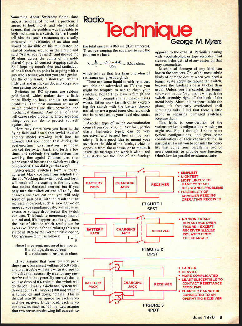
This leads to consideration of the various switch configurations which you might use. Fig. 1 through 3 show some typical configurations, and gives some considerations of their characteristics. In particular, I want you to consider the benefits that come from paralleling two or more contacts to provide one function. Ohm's law for parallel resistances states:
1/Rtotal = 1/R1 + 1/R2 + ...
In practical significance, two switch contacts in parallel will exhibit one-half the resistance if the contacts are equal. If either contact develops significant resistance.
BATTERY PACK CHARGING JACK RECEIVER FIGURE 1 SPST
- SIMPLEST
- LIGHTEST
- MOST LIKELY TO HAVE CONTACT RESISTANCE PROBLEMS
- POSSIBILITY OF CHARGER FEEDING OPERATING RECEIVER
BATTERY PACK CHARGING JACK RECEIVER FIGURE 2 DPST
- NO SIGNIFICANT ADVANTAGE OVER FIGURE 1 EXCEPT RECEIVER MAY BE ISOLATED FROM THE CHARGER
BATTERY PACK CHARGING JACK RECEIVER FIGURE 3 4PDT
- LARGER
- HEAVIER
- MORE COMPLICATED
- LEAST SUSCEPTIBLE TO CONTACT RESISTANCE PROBLEMS
- CHARGER CANNOT BE CONNECTED TO AN OPERATING RECEIVER
If either contact develops significant resistance for some reason, and the other one doesn't, the resistance of the parallel pair will still be less than the resistance of the good contact. Look at the equation and think about it, if you haven't already. I believe Fig. 3, as used by some of the biggest RC manufacturers, is the best way to go, in spite of the size and weight.
Clean and inspect your switch assembly frequently, to insure trouble-free flying. Look for signs of contamination, corrosion and damage, and if you can't make simple repairs, throw the thing away so you won't be tempted to use it in an "emergency." Pay particular attention to the wires at the points where they enter the switch and the plugs, looking for broken wires and soft spots (which often conceal wires that have broken inside the insulation). If you protect your switch assembly, it will protect your plane.
Please send ideas that you would like to see discussed to the address below. If you wish a personal reply, include a stamped, self-addressed envelope.
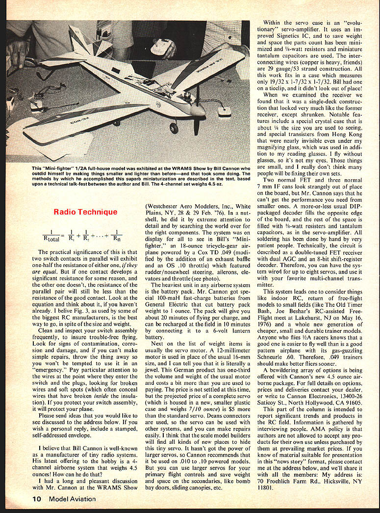
I believe that Bill Cannon is well-known as a manufacturer of tiny radio systems. His latest offering to the hobby is a 4-channel airborne system that weighs 4.5 oz.! How can he do that?
I had a long and pleasant discussion with Mr. Cannon at the WRAMS Show (Westchester Aero Modelers, Inc., White Plains, NY, 28 & 29 Feb. '76). In a nutshell, he did it by extreme attention to detail and by searching the world over for the right components. The system on display for all to see in Bill's "Mini-fighter," an 18-ounce tricycle-gear airplane powered by a Cox TD .049 (modified by the addition of an exhaust baffle and an OS .10 throttle) which featured rudder/nosewheel steering, ailerons, elevators and throttle (see photo).
The heaviest unit in any airborne system is the battery pack. Mr. Cannon got special 100-maH fast-charge batteries from General Electric that cut battery pack weight to 1 ounce. The pack will give you about 20 minutes of flying per charge, and can be recharged at the field in 10 minutes by connecting it to a 6-volt lantern battery.
Next on the list of weight items is usually the servo motor. A 12-millimeter motor is used in place of the usual 16-mm size, and I can tell you that it is literally a jewel. This German product has one-third the volume and weight of the usual 16-mm motor and costs a bit more than you are used to paying. The price is not settled at this time, but the projected price of a complete servo (which is housed in a new, smaller plastic case and weighs 7/10 ounce) is $5 more than the standard servo. Deans connectors are used, so the servo can be used with other systems, and you can make repairs easily. I think that the scale model builders will find lots of uses for this small servo. It hasn't got the power of larger servos, so Cannon recommends that it be used on .010 to .10 powered models. But you can use larger servos for your primary flight controls and save weight and space on the secondaries, like bomb bay doors, sliding canopies, etc.
Within the servo case is an "evolutionary" servo-amplifier. It uses an improved Signetics IC, and to save weight and space the parts count has been minimized and 1/8-watt resistors and miniature tantalum capacitors are used. The interconnecting wires (copper is heavy, friends) are 29 gauge/53 strand construction. All this work fits in a case which measures only 19/32 x 1-7/32 x 1-7/32. Bill had one on a tieclip, and it didn't look out of place!
When we examined the receiver we found that it was a single-deck construction that looked very much like the former receiver, except shrunken. Notable features include a special crystal case that is about 1/4 the size you are used to seeing, and special transistors from Hong Kong that were nearly invisible even under my magnifying glass, which was used in addition to my reading glasses. I fly without glasses, so it's not my eyes. Those things are small, and I really don't think many people will be flying their own sets.
Two normal FETs and three normal 7 mm IF cans look strangely out of place on the board, but Mr. Cannon says that he can't get the performance you need from smaller ones. A more-or-less usual DIP-packaged decoder fills the opposite edge of the board, and the rest of the space is filled with 1/8-watt resistors and tantalum capacitors, as in the servo-amplifier. All soldering has been done by hand by very patient people. Technically, the circuit is described as a double-tuned FET-receiver with dual AGC and an 8-bit shift-register decoder. Therefore, you can have the system wired for up to eight servos, and use it with your favorite multi-channel transmitter.
This system leads one to consider things like indoor R/C, return of free-flight models to small fields (like the Old Timer Bash, Joe Beshar's RC-assisted Free-Flight meet at Lakehurst, N.J. on May 16, 1976) and a whole new generation of cheaper, small and durable trainer models. Anyone who flies R/C at racetracks knows that a good one is easier to fly well than is a good pattern airplane with its gas-guzzling Schreurle .60. Therefore, .049 trainers should make better flyers sooner.
A bewildering array of options is being offered with Cannon's new 4.5 ounce airborne package. For full details on options, prices and deliveries contact the dealer or write to Cannon Electronics, 13400-26 Saticoy St., North Hollywood, CA 91605.
This part of the column is intended to report significant trends and products in the RC field. Information is gathered by interviewing people. AMA policy is that authors are not allowed to accept any products for review or free samples; items are purchased at prevailing market prices. If you know of material suitable for presentation in this "news story" format, please contact me at the address below, and I'll share it with the readers. My address is: 70 Froehlich Farm Rd., Hicksville, NY 11801.
Transcribed from original scans by AI. Minor OCR errors may remain.

