
Radio Technique
George M. Myers
A lot has happened in and around my personal life this past month: Lee Anne and Corey informed me of a new grandchild in production. Geoffrey visited for a few days (his job usually keeps him in the Inter-mountain West). Chris announced his engagement to Terry. My mother-in-law, Anne, who lived with me, died. Two blizzards fell on Long Island. I've helped develop "Sky Day" at a local college, helped a friend put together an article on his plane (which should appear in this magazine soon), gave talks at a couple of local clubs, and put off the income tax to the last minute. It should come as no surprise, then, when I say that I haven't finished the helicopter (a Baron 20, powered with an OS Wankel — I talked about it last month), so I can't tell you how it flies inverted.
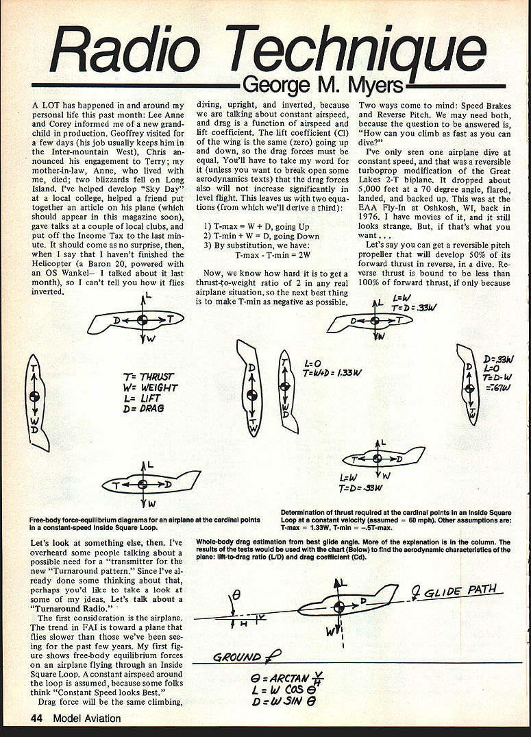
Free-body equilibrium and thrust equations
The first consideration is the airplane. The trend in FAI is toward planes that fly slower than those we've been seeing for the past few years. My first figure shows free-body equilibrium forces on an airplane flying through an Inside Square Loop. A constant airspeed around the loop is assumed, because some folks think "constant speed looks best."
- Drag force will be the same climbing, diving, upright, and inverted because we are talking about constant airspeed, and drag is a function of airspeed and lift coefficient.
- The lift coefficient (Cl) of the wing is the same (zero in the zero-lift portions) going up and down, so the drag forces must be equal. (You can check aerodynamics texts if you like; the drag forces do not increase significantly in level flight for this assumption.)
This leaves us with two equations (from which we'll derive a third):
- T-max = W + D, going up
- T-min = W − D, going down
- By substitution: T-max − T-min = 2W
Now, we know how hard it is to get a thrust-to-weight ratio of 2 in any real airplane situation, so the next best thing is to make T-min as negative as possible.
Two ways come to mind: speed brakes and reverse pitch. We may need both, because the question to be answered is, "How can you climb as fast as you dive?"
Reverse thrust example and derivation
I've only seen one airplane dive at constant speed, and that was a reversible-turboprop modification of the Great Lakes 2-T biplane. It dropped about 5,000 feet at a 70° angle, flared, landed, and backed up. This was at the EAA Fly-In at Oshkosh, WI, back in 1976. I have movies of it, and it still looks strange. But, if that's what you want...
Let's say you can get a reversible-pitch propeller that will develop 50% of its forward thrust in reverse, in a dive. Reverse thrust is bound to be less than 100% of forward thrust, if only because the propeller is twisted in the wrong direction for reverse flow. Even if we used a constant-pitch propeller (like a model helicopter main rotor), the airflow around the propeller would be all wrong, because it would approach from the front, go past the prop, and after working past the wing and the nose of the fuselage, enter from the rear.
If we assume that we really can develop 50% reverse thrust after all that, then equation (3) becomes:
- T-max − (0.5 T-max) = 2W
- which simplifies to: T-max = 1.33 W
This looks like a reasonable situation. But is it reasonable? What speed does it imply?
Substituting in equation (1) and simplifying yields:
- D = 0.33 W
(Useful geometry/trig relations used elsewhere:)
- Θ = arctan(H/V)
- L = W cos Θ
- D = W sin Θ
Drag estimate and glide tests
We need some kind of drag estimate for the whole airplane. One way to get it would be to do some engine-off glide tests, varying the glide speed to get the best possible range. Measure distance traveled versus distance dropped, and the time of the glide.
- Expect a 6:1 glide ratio from a Cessna 172–type airplane, and glide ratios up to about 15:1 for a clean, retract-gear pattern plane.
- Glide speed should measure out at 20 to 40 mph, depending on the design.
- Whatever you measure, the distance ratio can be taken as the lift-to-drag ratio (L/D) for that airplane at that speed.
For this example, let's say you measure an approximate glide ratio of 12:1 at a glide speed of 30 mph.
- The same L/D applies for level flight at the same speed. Remember that Lift = Weight in level flight.
- Suppose your airplane weighs 8 pounds. The whole-body drag force, flying level at 30 mph, will be 1/12th of 8 lb = 0.67 lb. Diving at 30 mph with the wing at the angle for zero lift would be about the same.
Since the estimated diving drag force needed was D = 0.33 W = 0.33 × 8 = 2.67 lb, equation (6) is telling us that we need a drag parachute as well as reverse thrust to dive at 30 mph — or we should decide to dive fast enough to develop 2.67 lb of drag.
Example glide table
The following lists times in seconds for various speeds (mph) for several glides, assuming the stopwatch starts as the plane passes eye level (taken as 5 ft) and is stopped when it hits the ground some distance away. Equivalent L/D ratios and whole-body coefficients of drag (Cd) are calculated, neglecting ground effect and assuming the pilot does not flare for landing.
Distance (ft) L/D Cd Time (s) @ 20 mph | 30 mph | 40 mph 25.00 5.00 0.20 0.85 | 0.57 | 0.43 30.00 6.00 0.16 1.02 | 0.68 | 0.51 35.00 7.00 0.14 1.19 | 0.80 | 0.60 40.00 8.00 0.12 1.36 | 0.91 | 0.68 50.00 10.00 0.10 1.70 | 1.14 | 0.85 60.00 12.00 0.08 2.05 | 1.36 | 1.02 75.00 15.00 0.07 2.56 | 1.70 | 1.28 80.00 16.00 0.06 2.73 | 1.82 | 1.36 100.00 20.00 0.05 3.41 | 2.27 | 1.70
Speed required
The equation for drag in points of force is D = Cd · S · q, where:
- Cd is a dimensionless coefficient,
- S is characteristic area in ft² (about 5 ft² is typical for a model of this type), and
- q = dynamic pressure in lb/ft² = 0.001189 × V² (for standard day at sea level, V in ft/s).
You just want the drag force to be 2.67 / 0.67 = 4 times larger. Drag varies as V², so you need the velocity multiplied by sqrt(4) = 2. Thus, 30 mph × 2 = 60 mph.
Can we fly at that speed? Modern pattern planes fly faster than that when drawing all possible horsepower from a .60 engine. If we want to fly at 60 mph when level, all we need to do is use less power. The real trick, then, is to pick a combination of airplane, engine, and reversible-pitch propeller such that:
- T-max ≈ 1.33 W and
- T-min ≈ −0.67 W (i.e., the reverse thrust magnitude about 0.67 W).
Beyond that, all we need is a two-position propeller-pitch control on the transmitter — and it would also be nice to have an additional detent on the throttle to mark the throttle setting for level flight at our chosen design speed (60 mph, in this example).
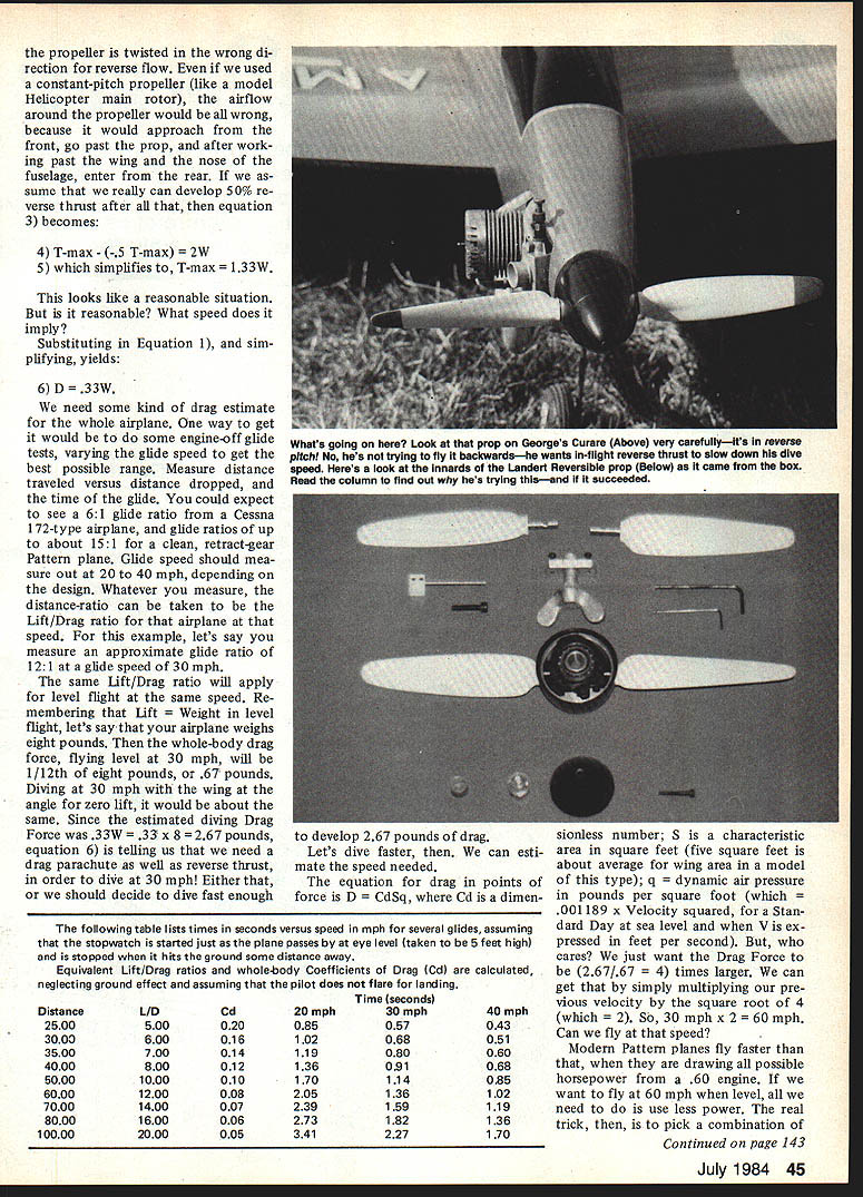
Test propeller and Turnaround transmitter
For test purposes, I tried an RC-Verstell-Propeller by J. Landert, CH-8625 Gossau, Tel. (01) 953 2681, which I bought from someone at the Toledo Show in 1981 (according to the date I marked on the box). It may still be available. It seems to be imported from Germany, is 11 inches in diameter, and changes pitch ±15°. If the importer is still in business, let me know and I'll pass it on.
Fitted to my Curare and controlled by the landing-gear switch to act like a two-position propeller, the Landert prop gave me a chance to test my theoretical Turnaround transmitter. I was kept pretty busy learning to fly the propeller and the airplane at the same time. To avoid changing prop pitch at full throttle, I tried to school myself to:
- Throttle down,
- Flip the propeller reversing switch,
- Throttle up (in reverse pitch) for the dive,
- Throttle down again, then initiate the pullout while throttling up to the detent (which I filed into the throttle-stick ratchet) for level flight.
It was a lot to do, and the main thing I learned was that I need a lighter Curare. Other than that, it worked. One thing for sure — it made me very careful with my landings. You sure don't want to damage that prop!
If anyone is thinking seriously about building a Turnaround transmitter, my suggestion is to implement the propeller-pitch control as a two-position affair with end-point control. The simplest way I can think of to do that is to use a buddy-box–type pushbutton on Channel 5 of an Ace Silver Seven transmitter. This setup ensures that the pitch won't be changed accidentally by someone fooling with the transmitter. Many of the new RC systems have end-point adjustment (EPA) on their auxiliary controls, so they could be used in the same way.
George M. Myers 70 Froehlich Farm Rd. Hicksville, NY 11801
Transcribed from original scans by AI. Minor OCR errors may remain.

