
Radio Technique: Receiver Repairs
George M. Myers
I HAVE DECIDED that I am primarily a flier. Building airplanes and repairing models and radios is something that I do out of necessity. Therefore, when I have to fix a radio, I try all of the simple ways first. My workbench has an oscilloscope, vacuum-tube voltmeter, assorted signal generators and other gadgets like special probes for the above. Probably yours doesn't, therefore it would be useless to describe techniques which require them. The following discussion will emphasize procedures that require tools normally found in a model-builder's shop. If you don't have a multi-tester (Volt-Ohm Meter) please get one. $20 should be enough to buy a good one at your local electronics supply house or mail-order shop. The important thing to look for is DC voltage scales of about 1.5, 6 and 12 volts full scale, and a sensitivity of 20,000 or more ohms/volt. You should also have a resistance (ohms) scale which shows about 50 ohms in the center of the arc and has multipliers on the selector switch of X1, X10, X100 and X1000 (or X1K).
Let's begin by assuming that your radio system is inoperative. How did it get that way? If the radio was working fine until the crash, we know enough to begin by looking for crash-type damage: check for a broken crystal, broken wires, missing antenna and other things of that nature. On the other hand, if everything was working fine last month and now it won't play, we begin by checking the battery packs for open or shorted cells; by checking the charger to make sure that it's doing its job; and by looking for dirt and corrosion that prevents the switch and the plugs from making contact. Whatever you do, do it systematically and keep records. If you try to do it all in your head you can be sure that you will waste time.
Suppose that you can't find anything obviously wrong with the system. The smart thing to do is to eliminate possibilities one at a time. Is the transmitter putting out a signal? There are several ways to find out. You could switch on and listen for the scream "I'm hit!" but I don't think that your flying buddies would appreciate that test technique. Get the frequency pin (the clothespin with the same colors on it as the flag on your antenna) and find somebody with a set on the same frequency as yours. Ask him to turn on his receiver and to turn on your transmitter. See if you can make his servos move in a controlled manner. Check ground range. It should be about the same as you used to have with your receiver. If so, your transmitter is OK. The control functions may show up in different places (for example aileron and rudder may exchange positions on your transmitter sticks) but that is perfectly acceptable. The various manufacturers don't always agree on which pulse comes first, and even if they did, your buddy can plug any servo into any receptacle on the receiver that pleases him, so finding a control function out of place is nothing to worry about.
If you are at home, you can bring your transmitter antenna near an operating transistor portable radio. Tune the receiver up and down the dial. You should hear a "brrrrr" sound between stations. Check by turning the transmitter off. If the sound goes away, your transmitter is putting out a signal. Another test is to bring the transmitter next to a TV which is operating on VHF channel 2 (or 27-MHz transmitters on channel 4 for 72 MHz). You should hear the "brrrrr" sound in the loudspeaker and see horizontal black-and-white bars in the picture. It may be necessary to disconnect the TV antenna and temporarily attach a 36-in. piece of wire to the TV antenna terminal (only one, not both) to see this effect, if you have an outside antenna for the TV. Another simple check is to turn the transmitter on and look at the meter on it. If the manufacturer supplied needle is in its normal position, the transmitter is working. It's really surprising how many people never look at that meter, and as a result they forget that it's there.
Transmitter OK, System Inoperative
Wrap the receiver antenna one turn around the transmitter antenna, and turn everything on. If you can now control your servos, chances are that the receiver crystal is broken. Remove the receiver from the airplane, disconnect everything, gather up and hold any dangling wires, remove any foam padding, hold the receiver near your ear and shake it (the receiver). You may hear the faint tinkle of a broken crystal, which is positive proof of the problem. A replacement crystal can be obtained for about $8. Make certain the replacement crystal is the correct one for your receiver, because all crystals are not alike, even though they are for the same frequency. Some receivers use "second overtone" crystals, others use "third overtone", particularly on 72-MHz, and those variations may inhibit me from trying to list them here.
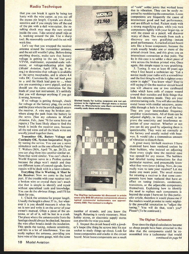
Removing and replacing a crystal is a simple job for anyone who has ever done work on a printed circuit board. The crystal is non-directional so it may be inserted either way. Retuning may be necessary. Ninety-eight times in 100 it isn't. Usual cautions apply. Use 60/40 lead/tin solder, rosin-cored, 25-40 watt, 650°F iron. Minimize heating time to avoid creating a cold joint. The previous sentence means nothing to someone who hasn't soldered on a receiver until you have built a Heathkit or some other manufacturer's kit. Electronic kits usually have very good soldering instructions and the practice you get building the kits will go a long way toward protecting your investment in the RC system. For your first kit I would suggest the Heath IM-18 VTVM at about $40. (Schlumberger Products Corp., P.O. Box 167, Saint Joseph, MI 49085.) If you build this, you won't need the milli-tester described above. Back to that crystal. When you do solder in a new crystal, be advised... that you can break it again by being too hasty with the wire cutter, as you cut off the excess pin length. Crystals are shock-sensitive and if you simply bite off the end of the pin with a dull wire-cutter, the resulting shock may snap the new crystal inside the case. Take several small nips at it, working around the pin. Use a sharp tool. Be reasonably careful and the set will work fine.
Let's say that you wrapped the receiver antenna around the transmitter antenna, and the set still wouldn't play. Before doing anything drastic, make sure that battery voltage is getting to the set. Use your VTVM, multimeter, expanded-scale voltmeter, or voltage-indicating pilot light (Model Aviation, April 1976, pg. 9 et. seq.) to determine that voltage is available at the servo receptacles, and is above 4.4 volts DC. Customarily, the red lead goes to + and the black lead goes to -, when you are examining a servo pigtail, and you should use the same orientation for the leads of your test instrument. It's unlikely that you will damage anything if you get it wrong, however.
If no voltage is getting through, check for voltage at the battery plug, the switch and the place where the switch pigtail enters the receiver. A wire may be broken anywhere along the path from the battery to the servo. (See my columns in Model Aviation, Feb., June '76 for some hints on repairs.) The least likely place to find the break is inside the receiver case, because all the red wires and all the black wires are usually joined together there.
Transmitter OK, Battery Voltage and Continuity OK, System Inoperative:
Begin by testing the servos. You can use a servo stimulator such as the one offered by Peter T. Walters (MA, April '76, pp. 20-22), or you can plug them into another similar set. Note that word similar. You can't check a World Engines servo in a Proline system because the plugs won't match and they use different types of control signals. Servo repairs will be dealt with in a later column.
Everything Else is Working, It Must be the Receiver:
Now we come to the hard part. If the trouble with your receiver isn't a broken wire or crystal there isn't much else that is simple to identify and repair without specialized tools and knowledge. You can do the obvious things, and I'll list them for you.
- Check the antenna for proper length. Usually the length is about 37 in., but whatever it is you should measure it when the set is new and write it on the cover of your owner's manual. Often a piece of the antenna, or all of it, will be lost in a crash. The place where the antenna exits from the fuselage should always be checked, because the wire often breaks inside the insulation. This spoils the tuning, reduces sensitivity, and lets in a lot of interference. You can easily replace the antenna, providing you have wire of the same gauge, with the same number of strands, and you know the length. Retuning is rarely necessary. Most hobby stores, or electronic supply stores can provide the wire you need.
- Inspect the circuit board with a jeweler's loupe (the thing the jeweler screws into his eye socket to study things up close). Look for loose components and cracks in the circuit board. Most loose components are a result of "cold" solder joints that worked loose due to vibration. They can be easily repaired by resoldering the connection. Loose components are frequently the cause of intermittent good and bad performance, and are difficult to find. Patient study with a strong magnifying glass, while you rock components lightly with your finger-tip, or with the eraser on a pencil, will discover many of them. A cracked circuit board acts like a loose component, because the crack usually breaks one or more of the printed circuit lines, and this gives you an intermittent connection at that point. The fix in this case is to solder a short piece of wire across the broken printed wire. Once again, this simple repair is very gratifying.
- Tuning. It was at least 40 years ago when I first heard a technician say "Let a novice inside your radio with a screwdriver and the first thing he will do is tighten every screw in sight!" You know what? They're still saying it! On the receiver circuit board you will observe one or two cardboard tubes which have coils of copper wound around their outsides and little things that look like setscrews inside. They are your antenna-tuning coils. You'll also see three metal boxes with similar setscrews, accessible through a hole in the top of the box. They are your intermediate frequency amplifier transformers. All of them can be adjusted slightly, in time of need, to improve the sensitivity and interference rejection of your receiver. Whether or not you can do any good by adjusting them is questionable. They were set correctly at the factory and usually sealed with beeswax. It would take a tremendous amount of vibration to disturb them.
A great many kit-built receivers I have examined have been rendered useless by their builders, who insisted on adjusting them every single time the receiver case was opened for any reason. The builders had detailed tuning instructions for that particular receiver, and presumably knew what they were (over-) doing. Now, do you really want to tune your receiver? Let me make one more point. The usual reason for retuning a receiver is that some components have been replaced that have an effect on tuning (resistors, condensers, transistors, or the adjustable components themselves). Explaining how to identify the need to replace such components is beyond the scope I have set for this particular article, therefore it would please me if the readers would promise to resist mightily the powerful temptation to "adjust the tuning." You will do that, won't you? Please? (To be continued.)
Radio Technique: Receiver Repairs
I have decided I am primarily a flier. Building airplanes and repairing models and radios grew out of necessity. Therefore, when I have to fix a radio I try simple ways first. My workbench has an oscilloscope, vacuum-tube voltmeter, assorted signal generators and other gadgets like special probes. Probably yours doesn't, therefore it would be useless to describe techniques which require these items. The following discussion will emphasize procedures which require tools normally found in the model-builder's shop. If you don't have a multi-tester (Volt-Ohm Meter), please get one. $20 should be enough to buy a good one at your local electronics supply house or mail-order shop. The important thing is to look for DC voltage scales about 1.5, 6 and 12 volts full scale and a sensitivity of 20,000 ohms/volt. It should also have a resistance (ohms) scale that shows about 50 ohms at the center. A meter with multipliers or a selector switch X1, X10, X100, X1000 is desirable.
Let's begin assuming the radio system is inoperative. If it was working until a crash, you know enough to begin looking for crash-type damage: check for a broken crystal, broken wires, a missing antenna, and other things of that nature. On the other hand, if everything was working fine last month and now won't play, begin by checking battery packs for open or shorted cells, check the charger to make sure it's doing its job, and look for dirt or corrosion which prevents switches or plugs from making contact. Whatever you do, work systematically and keep records — try to remember what you have done, or you will waste time.
Suppose you can't find anything obviously wrong. A smart thing to do is to eliminate possibilities one at a time. Is the transmitter putting out a signal? There are several ways to find out. You could switch on a buddy's receiver and listen for a "scream" — "I'm hit" — but I don't think your flying buddies would appreciate that test technique. Get a frequency pin or a clothespin the same color as your antenna flag and find somebody who has set his transmitter to the same frequency as yours. Ask him to turn his transmitter on and his receiver off. See if you can make your servos move in a controlled manner. Check ground range; it should be about the same as you used to have when the receiver and transmitter gave fine control. Control functions may show up in different places — for example, aileron and rudder may be exchanged — because various manufacturers don't always agree which pulse comes first. If your buddy can plug a servo into your receiver and it pleases him, finding a control function out of place is nothing to worry about.
At home you can bring the transmitter antenna near an operating transistor portable radio. Tune the receiver up and down the dial; you should hear a "brrrr" sound between stations. Check by turning the transmitter off — the sound should go away; if so, the transmitter is putting out a signal. Another test is to bring the transmitter near a TV operating on VHF (some 27-MHz transmitters or 72-MHz transmitters may affect VHF sets). You should hear a "brrr" through the loudspeaker and may see horizontal black-and-white bars on the picture. It may be necessary to disconnect the TV antenna temporarily and attach a 36-inch piece of wire to the TV antenna terminal to see the effect if you have an outside antenna.
Another simple check is to turn the transmitter on and look at the meter supplied by the manufacturer — the needle should be in its normal position; if it is, the transmitter is working. It's really surprising how people never look at the meter and then forget the result.
Transmitter OK — system inoperative. Wrap the receiver antenna around your finger and turn the receiver antenna toward the transmitter antenna. If things will now control the servos, the chances are that the receiver crystal is broken. Remove the receiver from the airplane, disconnect everything, gather up the dangling wires, remove foam padding, hold the receiver near your ear and shake it. You may hear a faint tinkle — a broken crystal; positive proof of the problem. A replacement crystal can be obtained for about $8. Make certain the replacement crystal is for the correct receiver, because crystals look alike though they are not the same frequency. Some receivers use second-overtone crystals, others use third-overtone crystals (particularly in the 72-MHz area); enough variations exist to make identification important.
Removing and replacing a crystal is a simple job. Anyone who has ever done work on a printed-circuit board knows that the crystal is non-directional and may be inserted either way. Retuning may be necessary, but 98 times out of 100 it isn't. Usual cautions apply: use 60/40 lead/tin rosin-core solder, a 27–40 watt iron (about 650°F), minimize heating time and avoid creating a cold joint. If you haven't done much soldering, consider practicing on scrap before working on your receiver.
Electronic kits usually have printed circuit boards and parts arranged to make assembly and soldering easier.
Transcribed from original scans by AI. Minor OCR errors may remain.

