
Randy's Dime
IT'S ONLY FAIR to warn you. An RC sport trainer as versatile and economical as this one can be habit-forming.
Dime suits just about any mood. Take it up for slow flight—just puttering around, clipping weeds, and doing endless touch-and-goes—or go for tearing up the sky with reckless abandon—all on a small fuel budget.
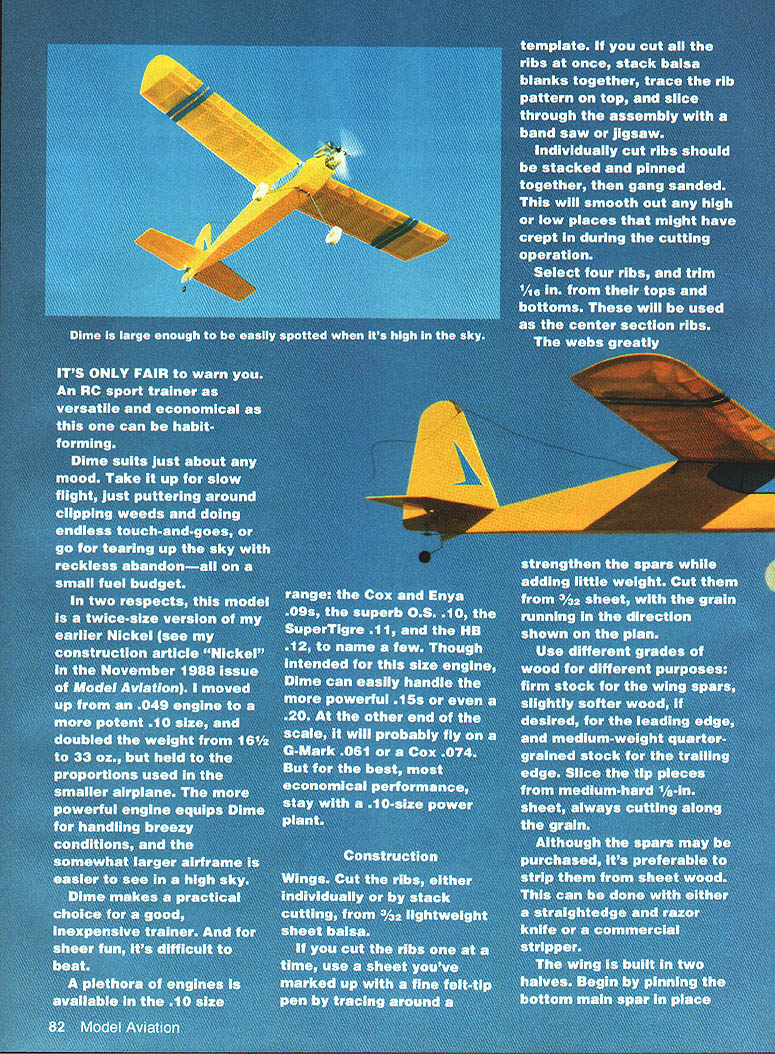
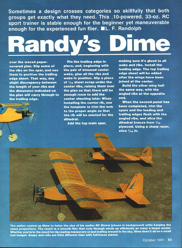
In two respects, this model is a twice-size version of my earlier Nickel (see my construction article "Nickel" in the November 1988 issue of Model Aviation). I moved up from an .049 engine to a more potent .10 size and doubled the weight from 16½ to 33 oz., while holding to the proportions used in the smaller airplane. The more powerful engine equips Dime for handling breezy conditions, and the somewhat larger airframe is easier to see in a high sky.
Dime makes a practical choice for a good, inexpensive trainer. And for sheer fun, it's difficult to beat.
A plethora of engines is available in the .10 size range:
- Cox and Enya .09s
- O.S. .10
- SuperTigre .11
- HB .12
Though intended for a .10-size engine, Dime can easily handle more powerful .15s or even a .20. At the other end of the scale, it may fly on a G-Mark .061 or a Cox .074, but for the best, most economical performance, stay with a .10-size power plant.
Construction
Wings
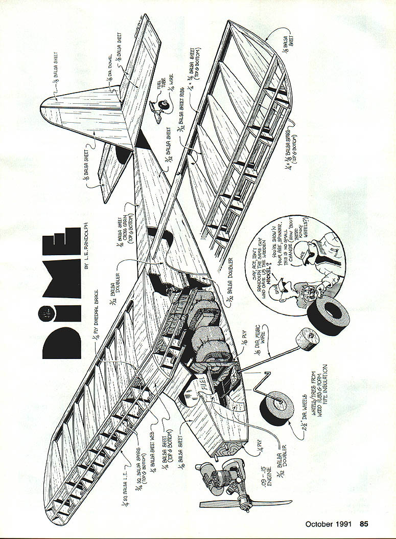
- Cut the ribs from 3/32-in. lightweight sheet balsa, either individually or by stack cutting.
- If cutting individually, mark a sheet with a fine felt-tip pen by tracing around a template.
- If cutting in a stack, trace the rib pattern on the top and slice through the assembly with a band saw or jigsaw.
- Stack and pin individually cut ribs, then gang-sand to smooth any high/low spots.
- Select four ribs and trim 1/16-in. from their tops and bottoms for use as center section ribs.
- Cut webs from 3/32-in. sheet with the grain running as shown on the plan; the webs greatly strengthen the spars while adding little weight.
- Use different grades of wood for different parts:
- Firm stock for spars
- Slightly softer wood for the leading edge (if desired)
- Medium-weight quarter-grained stock for the trailing edge
- Tip pieces sliced from medium-hard 1/8-in. sheet, cutting along the grain
- Spars may be purchased, but it's preferable to stripe them from sheet wood with a straightedge and razor or a commercial stripper.
Build the wing in two halves:
- Pin the bottom main spar in place over waxed paper on the plan.
- Slip some ribs on the spar and use them to position the trailing edge sheet so any slight rib-length discrepancy carries through to the trailing edge.
- Pin the trailing edge, then glue all ribs and webs in position, beginning with the pair of trimmed center webs.
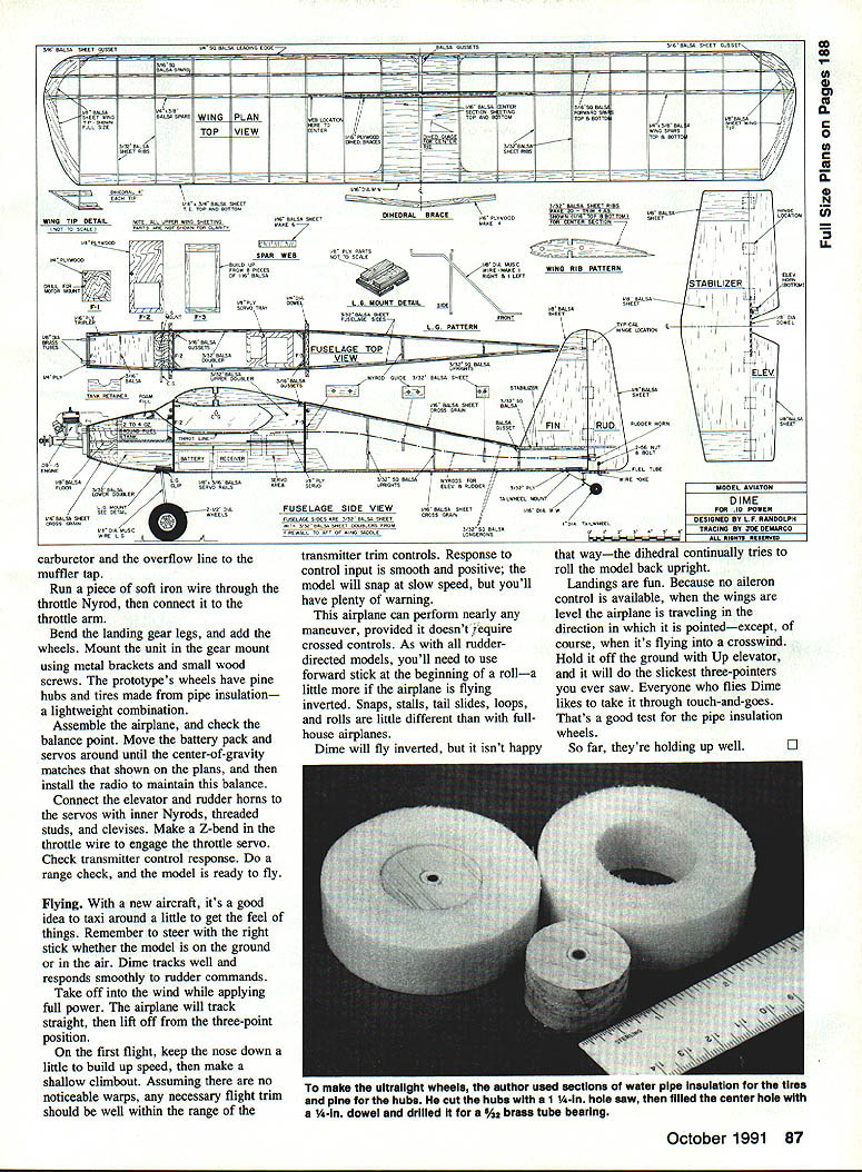
- Slip a piece of 1/16-in. scrap under the center ribs to raise them so there will be room for center sheeting later.
- When installing the center rib, trim the web to the proper angle so the rib will be slanted for the dihedral.
- Add the top main spar, glue it to all webs and ribs, and install the leading edge. The top trailing edge sheet will be added after joining the wings at the center.
Build the other wing half the same way with angled ribs at the opposite end. When the second panel is complete:
- Trim spars and leading/trailing edges flush with the angled ribs.
- Slice dihedral braces from 1/16-in. plywood. Using a sharp razor, slice 1/16-in. from the center ribs on each side of the main spars to fit the plywood dihedral braces.
- With one wing half flat and the other elevated about 6 in., install the plywood braces. Check all joints for fit before gluing.
- When the cement has set, install top and bottom front spars.
- Glue the tips to their ribs; tips are angled upward to be flush with the top of the top-spar stubs.
- Fill the area between the bottom spars and tips with scrap spar material.
- Add the top trailing edges and then the center-section sheeting, positioning the sheeting between—rather than over—the spars.
- Sand the completed wing and set it aside.
Stabilizer, elevator, and rudder
- Cut stabilizer, elevator, and rudder from medium-hard 1/8-in. sheet.
- Add cross-grained tips to the stabilizer to help eliminate warping.
- Join the stabilizer and elevator surfaces and sand the outlines to match.
- Inset the music-wire carry-through at the leading edge of the elevator and epoxy it in place.
- After the cement sets, cut the rudder clearance notch in the trailing edge.
Fuselage
- Cut the sides from medium 3/32-in. balsa sheet. Do not cut the wing saddle until doublers are glued in place.
- Cut doublers from 3/32-in. balsa and cement them in place along with 1/8-in. plywood triplers.
- Pin the sides together and block-sand to the matching outline. With the sides still pinned, cut the wing saddle and drill 1/4-in. holes for the wing-mounting dowels.
- Separate the sides and add 3/32-in. square uprights and servo-mounting rails.
- Cut out the firewall and two cabin formers. Epoxy strips of 3/32-in. plywood to the rear of the firewall as backups for wood screws anchoring the engine mount.
- Drill the firewall for throttle, fuel, and overflow lines; drill the front cabin former for the throttle line.
Begin assembly:
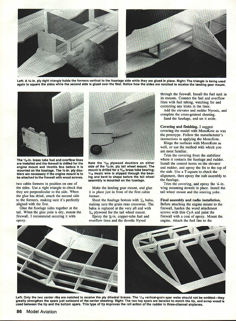
- Glue the sides together, using a right triangle to ensure side formers are perpendicular.
- When dry, attach the second side formers, verifying alignment with the first. Dry-mount the firewall and secure with epoxy as recommended.
- Make the landing-gear mount and glue it just forward of the first cabin former.
- Sheet the fuselage bottom with 1/16-in. balsa, making sure the grain runs crosswise.
- Replace the very aft end balsa with 1/16-in. plywood for the tail-wheel mount and epoxy a 1/16-in. brass tube for the tail-wheel bearing.
Installations:
- Slip the 1/16-in. copper-tube fuel overflow and throttle Nyrod through the firewall.
- Install the fuel tank in its mounts. Connect fuel and overflow lines and fuel tubing, checking and correcting kinks.
- Add elevator and rudder Nyrods.
- Complete cross-grained sheeting and sand the fuselage; set it aside.
Covering and final assembly
- I suggest using MonoKote; the prototype used MonoKote. Follow the manufacturer's instructions when applying.
- Hinge surfaces with MonoKote using your preferred method.
- Trim covering where the stabilizer contacts the fuselage and at the rudder hinge line.
- Install control horns on the elevator and rudder, and epoxy the fin to the top of the stabilizer.
- Use a T-square to check alignment when epoxying the stabilizer assembly to the fuselage. Trim covering as required.
- Epoxy 3/16-in. wing-mounting dowels in place.
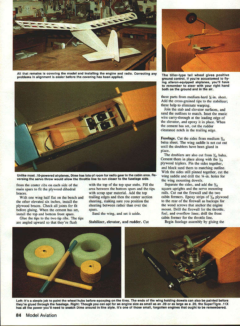
- Install the tail-wheel mount and steering yoke.
Note: 1/32-in. plywood doublers go on either side of the engine-mount area. Drill for the throttle line before installing the engine-mount doublers.
Final assembly and radio installation
- Before attaching the engine mount, harden the wood around the attachment screws with thin CA, then paint the firewall with a coat of epoxy.
- Mount the engine and attach the fuel line.
- Paint wheel hubs before epoxying tires. The tire ends of the wing-holding dowels can also be painted before they're glued through the fuselage.
- Run a piece of soft iron wire through the throttle Nyrod and connect it to the throttle arm. Make a Z-bend in the throttle wire to engage the throttle servo.
- Bend the landing-gear legs and add the wheels. Mount the gear in the gear mount using metal brackets and small wood screws. (The prototype's wheels have pine hubs and tires made from pipe insulation—a lightweight combination.)
- Assemble the airplane and check the balance point. Move the battery pack and servos until the center of gravity matches that shown on the plans, then install the radio to maintain this balance.
- Connect the elevator and rudder horns to the servos with inner Nyrods, threaded studs, and clevises.
- Check transmitter control response and perform a range check.
Flying
- Taxi the new aircraft a little to get the feel of it. Remember to steer with the right stick whether the model is on the ground or in the air. Dime tracks well and responds smoothly to rudder commands.
- Take off into the wind while applying full power. The airplane will track straight and lift off from the three-point position.
- On the first flight, keep the nose down slightly to build up speed, then make a shallow climbout. Assuming no noticeable warps, any necessary flight trim should be within the range of the transmitter trim controls.
- Response to control input is smooth and positive; the model will snap at slow speed but with plenty of warning.
- The airplane can perform nearly any maneuver that doesn't require crossed controls. With rudder-elevator-directed models you'll need to use four-stick at the beginning of a roll—a bit more if flying inverted.
- Dime will fly inverted but tends to roll upright because the dihedral tries to correct it.
- Landings are fun: without ailerons, when the wings are level the airplane travels in the direction it is pointed (except in a crosswind). Hold it off the ground with up elevator for slick three-pointers. Touch-and-goes are a favorite test for the pipe-insulation wheels; so far, they're holding up well.
Transcribed from original scans by AI. Minor OCR errors may remain.

