
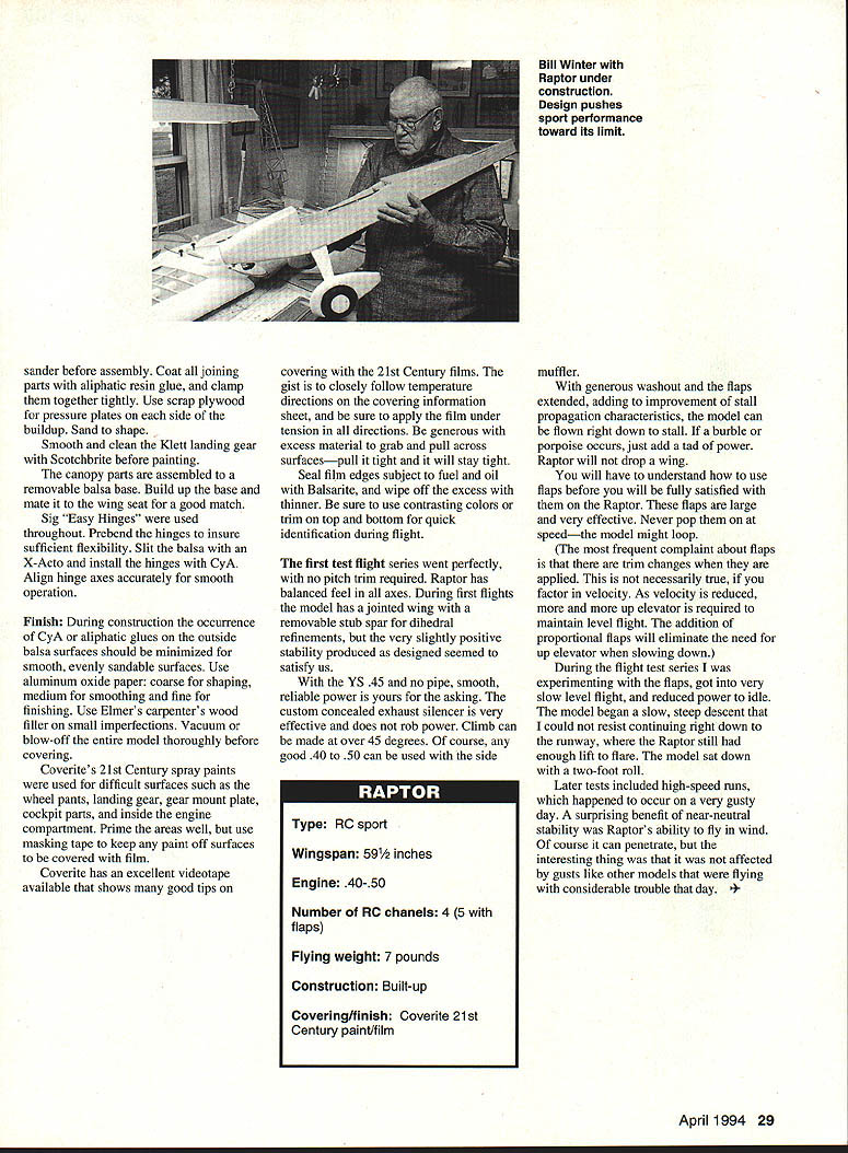
Raptor
Bill Winter & John Hunton
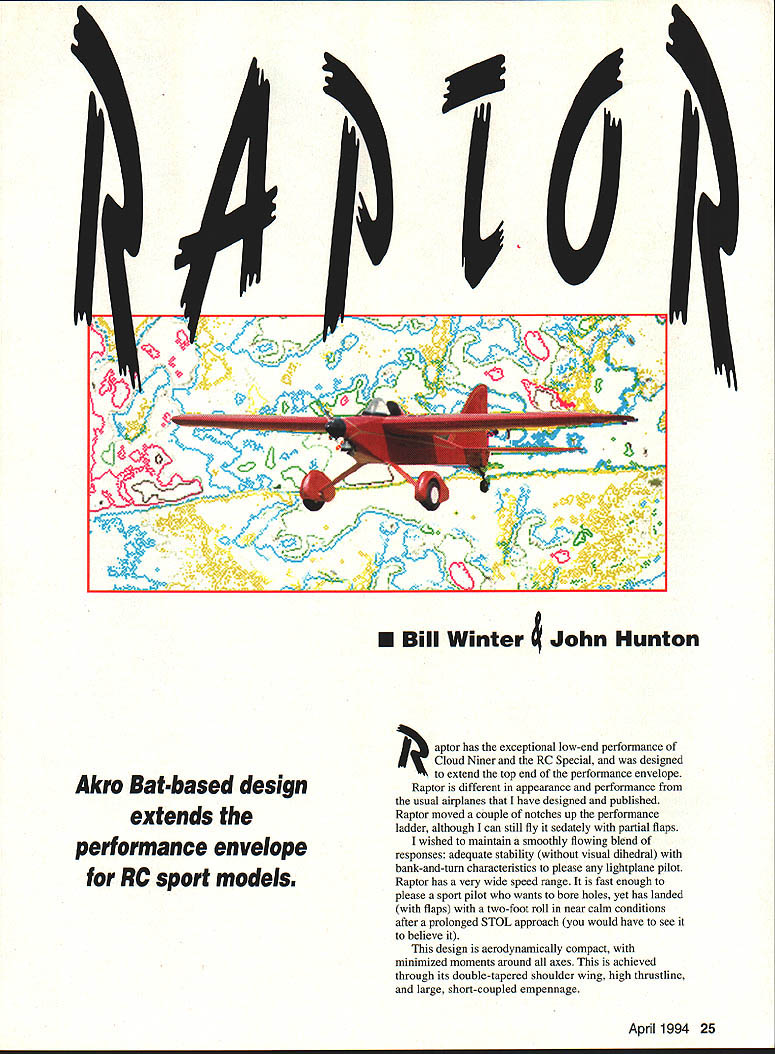
Akro-Bat–based design extends the performance envelope for RC sport models.
Raptor shares the exceptional low-end performance of the Cloud Niner and the RC Special, and was designed to extend the top end of the performance envelope. It differs in appearance and performance from the usual airplanes I have designed and published. Raptor moved a couple of notches up the performance ladder, although it can still be flown sedately with partial flaps.
I aimed to maintain a smoothly flowing blend of responses: adequate stability (without visual dihedral) with bank-and-turn characteristics to please any lightplane pilot. Raptor has a very wide speed range. It is fast enough to please a sport pilot who wants to bore holes, yet has landed (with flaps) with a two-foot roll in near-calm conditions after a prolonged STOL approach.
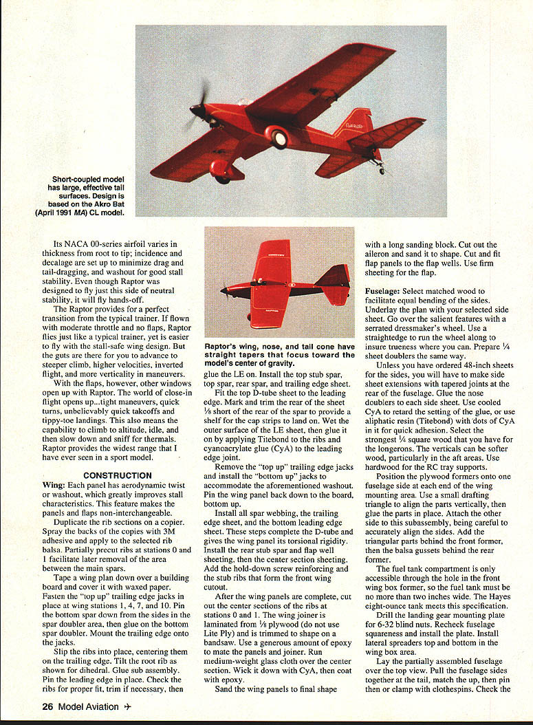
This design is aerodynamically compact, with minimized moments around all axes. This is achieved through its double-tapered shoulder wing, high thrustline, and a large, short-coupled empennage.
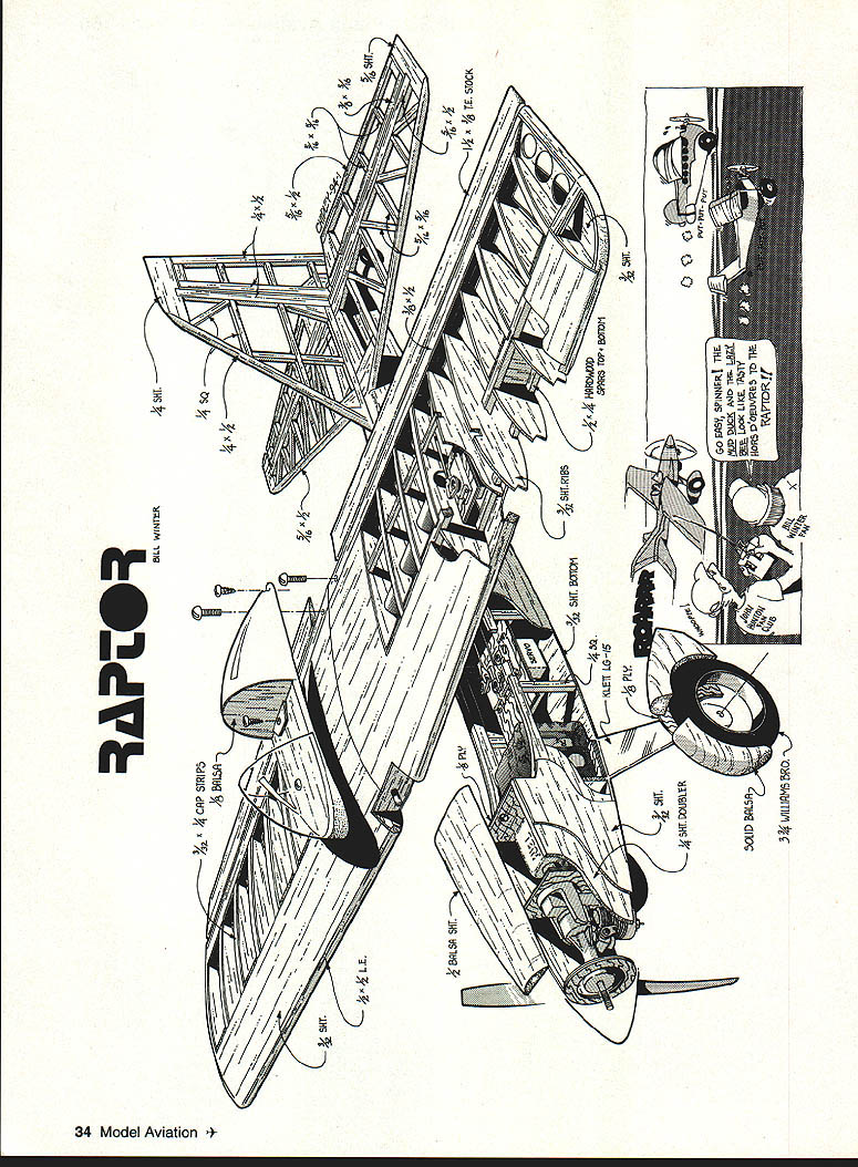
Construction
Wing
Each panel has aerodynamic twist (washout), which greatly improves stall characteristics. This feature makes the panels and flaps non-interchangeable.
- Duplicate the rib sections on a copier. Spray the backs of the copies with 3M adhesive and apply them to the selected rib balsa. Partially precut ribs at stations 0 and 1 to facilitate later removal of the area between the main spars.
- Tape a wing plan down over a building board and cover it with waxed paper. Fasten the "top up" trailing-edge jacks at wing stations 1, 4, 7, and 10. Pin the bottom spar down; glue the bottom spar doubler. Mount the trailing edge onto the jacks, slip the ribs into place centering on the trailing edge, tilt the root rib as shown for dihedral, and glue the subassembly.
- Pin the leading edge in place. Check ribs for proper fit, trim if necessary, then glue the leading edge (LE).
- Install the top stub spar, top spar, rear spar, and trailing-edge sheet. Fit the top D-tube sheet to the leading edge and mark/trim its rear short of the rear spar to provide a shelf for the cap strips. Wet the outer surface of the LE sheet with glue; apply Titebond to the ribs and cyanoacrylate (CyA) to the leading-edge joint.
- Remove the "top up" trailing-edge jacks and install the "bottom up" jacks to accommodate the washout. Pin the wing panel bottom-up to the board.
- Install all spar webbing, the trailing-edge sheet, and the bottom leading-edge sheet to complete the D-tube and give the panel torsional rigidity. Install the rear stub spar, flap-well sheeting, and center-section sheeting. Add hold-down screw reinforcing and the stub ribs that form the front wing cutout.
- After the panels are complete, cut out the center sections at rib stations 0 and 1. The wing joiner is laminated 1/8" plywood (use Lite Ply) and is trimmed to shape on a bandsaw. Use a generous amount of epoxy to mate the panels and joiner, run medium-weight glass cloth over the center section, wick down CyA, coat with epoxy, and sand the wing panels to final shape with a long sanding block.
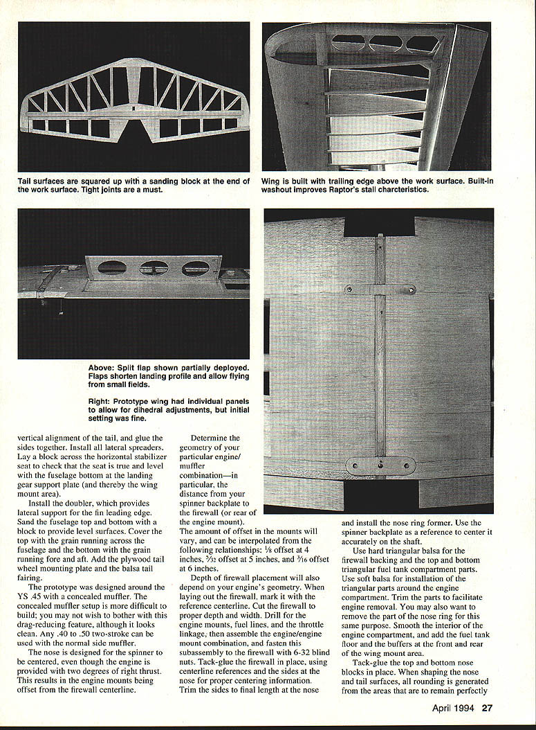
- Cut out the aileron and sand to shape. Cut and fit flap panels to the flap wells; use firm sheeting for the flap.
Fuselage
Select matched wood to facilitate equal bending of the sides. Underlay the plan with your selected side sheet and go over the salient features with a serrated dressmaker's wheel. Use a straightedge to run the wheel along to ensure trueness. Prepare sheet doublers the same way.
Unless you have ordered 48-inch sheets for the sides, make side-sheet extensions with tapered joints at the rear of the fuselage. Glue nose doublers to each side sheet. Use cooled CyA to retard setting, or use aliphatic resin (Titebond) with dots of CyA for quick adhesion. Select the strongest 3/32" square wood for the longerons; verticals can be softer wood, particularly aft. Use hardwood for the RC tray supports.
Position plywood formers onto the fuselage side at each end of the wing mounting area. Use a small drafting triangle to align the parts vertically, then glue. Attach the other side to this subassembly, carefully aligning the sides. Add triangular parts behind the front former, then balsa gussets behind the rear former.
The fuel-tank compartment is only accessible through the hole in the front wing-box former, so the fuel tank must be no more than two inches wide; the Hayes eight-ounce tank meets this specification. Drill the landing-gear mounting plate for 6-32 blind nuts, recheck fuselage squareness, and install the plate. Install lateral spreaders top and bottom in the wing-box area.
Lay the partially assembled fuselage over the top-view plan, pull the fuselage sides together at the tail, match the top, then pin or clamp with clothespins. Check vertical alignment of the tail and glue the sides together. Install all lateral spreaders. Lay a block across the horizontal stabilizer seat to check that the seat is true and level with the fuselage bottom at the landing gear support plate (and thereby the wing mount area).
Install the doubler, which provides lateral support for the fin leading edge. Sand the fuselage top and bottom with a block to provide level surfaces. Cover the top with the grain running across the fuselage and the bottom with the grain running fore and aft. Add the plywood tailwheel mounting plate and the balsa tail fairing.
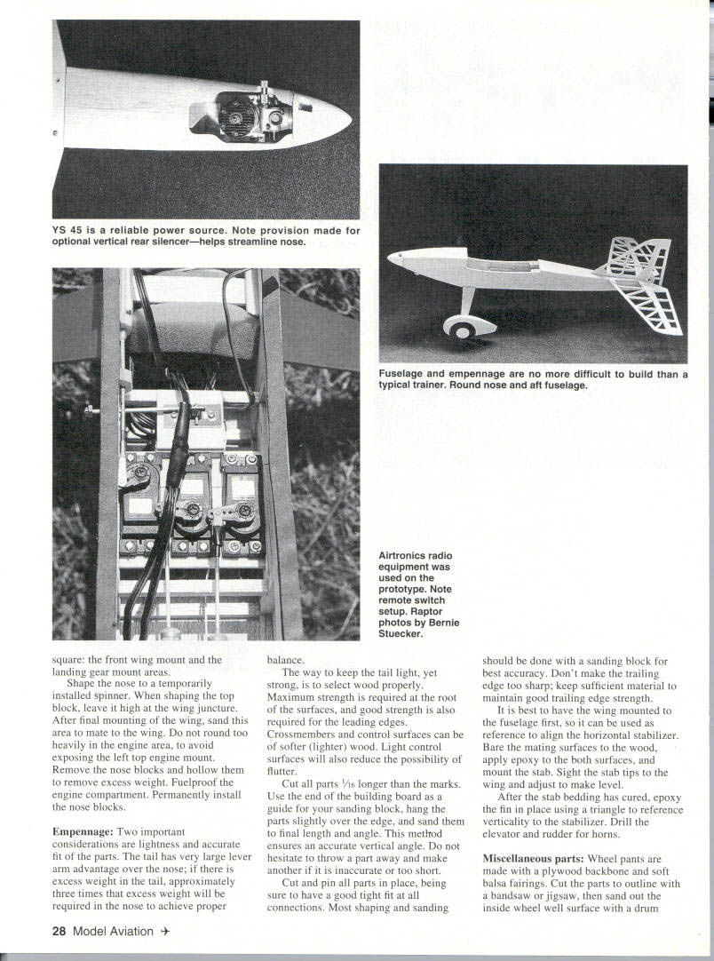
The prototype was designed around the YS .45 with a concealed muffler. The concealed muffler setup is more difficult to build; you may prefer the normal side muffler. Any .40–.50 two-stroke can be used with a side muffler.
The nose is designed for the spinner to be centered, even though the engine is provided with two degrees of right thrust; engine mounts are offset from the firewall centerline to accomplish this. Determine the geometry of your particular engine/muffler combination — in particular, the distance from your spinner backplate to the firewall (or rear of the engine mount). The amount of offset in the mounts can be interpolated from these relationships:
- 3/4" offset at 4" spinner-to-firewall distance
- 7/32" offset at 5"
- 3/16" offset at 6"
Depth of firewall placement will also depend on your engine's geometry. When laying out the firewall, mark it with the reference centerline. Cut the firewall to proper depth and width. Drill for the engine mounts, fuel lines, and throttle linkage; assemble the engine/engine-mount combination, and fasten this subassembly to the firewall with 6-32 blind nuts. Tack-glue the firewall in place, using centerline references and the sides at the nose for proper centering. Trim the sides to final length at the nose and install the nose ring former. Use the spinner backplate as a reference to center it accurately on the shaft.
Use hard triangular balsa for the firewall backing and the top and bottom triangular fuel-tank compartment parts. Use soft balsa for the triangular parts around the engine compartment and trim them to facilitate engine removal (you may want to remove part of the nose ring for this purpose). Smooth the interior of the engine compartment, add the fuel-tank floor, and add buffers at the front and rear of the wing mount area.
Tack-glue the top and bottom nose blocks in place. When shaping the nose and tail surfaces, all rounding is generated from the areas that are to remain perfectly flat. Square the front wing mount and the landing gear mount areas.
Shape the nose to a temporarily installed spinner. When shaping the top nose block, leave it high at the wing juncture; after final mounting of the wing, sand this area to mate with the wing. Do not round too heavily in the engine area to avoid exposing the left top engine mount. Remove the nose blocks and hollow them to remove excess weight. Fuelproof the engine compartment and permanently install the nose blocks.
Empennage
Two important considerations are lightness and accurate fit. The tail has a large lever-arm advantage over the nose; if there is excess weight in the tail, approximately three times that excess weight will be required in the nose to achieve proper balance.
Keep the tail light yet strong by selecting wood properly. Maximum strength is required at the root of the surfaces and good strength is required for the leading edges. Crossmembers and control surfaces can be softer (lighter) wood. Light control surfaces also reduce the possibility of flutter.
- Cut all parts 1/16" longer than the marks. Use the end of the building board as a guide for your sanding block, hang the parts slightly over the edge, and sand to final length and angle to ensure accurate vertical angles.
- Cut and pin all parts in place, ensuring tight fits at all connections. Most shaping and sanding should be done with a sanding block for best accuracy. Keep sufficient material at the trailing edge to maintain strength.
- Mount the wing to the fuselage first so it can be used as a reference to align the horizontal stabilizer. Bare the mating surfaces, apply epoxy to both surfaces, and mount the stabilizer. Sight the stabilizer tips to the wing and adjust to match.
- After the stabilizer bedding has cured, epoxy the fin in place using a triangle to reference verticality to the stabilizer. Drill the elevator and rudder for horns.
Miscellaneous parts
- Wheel pants: plywood backbone with soft balsa fairings; cut to outline and sand inside wheel well with a drum sander. Coat joining parts with aliphatic resin glue and clamp tightly; use scrap plywood as pressure plates on each side of the buildup; sand to shape.
- Landing gear: smooth and clean with Scotch-Brite before painting.
- Canopy: assemble canopy parts to a removable balsa base; build up the base and mate it to the wing seat for a good fit.
- Hinges: Sig "Easy Hinges" were used throughout. Prebend the hinges to ensure sufficient flexibility. Slit balsa with an X-Acto and install hinges with CyA. Align hinge axes accurately for smooth operation.
Finish
Minimize CyA or aliphatic glue on outside balsa surfaces during construction for smooth, evenly sanded surfaces. Use aluminum oxide paper: coarse for shaping, medium for smoothing, fine for finishing. Use Elmer's carpenter's wood filler on small imperfections. Vacuum or blow off the entire model thoroughly before covering.
Coverite's 21st Century spray paints were used for difficult surfaces such as wheel pants, landing gear, gear mount plate, cockpit parts, and inside the engine compartment. Prime these areas well, but use masking tape to keep paint off surfaces to be covered with film. Coverite has a videotape with tips on covering with the 21st Century films — follow temperature directions and apply film under tension in all directions. Be generous with excess material to pull tight across surfaces.
Seal film edges subject to fuel and oil with Balsarite, wiping off excess with thinner. Use contrasting colors or trim on top and bottom for quick identification in flight.
Flight testing and handling
The first test flights went perfectly, with no pitch trim required. Raptor has a balanced feel in all axes. During early flights the model had a jointed wing with a removable stab spar for dihedral refinements, but the very slightly positive stability produced as designed proved satisfactory.
With the YS .45 and no pipe, power is smooth and reliable. The custom concealed exhaust silencer is effective and does not rob power; climb can be made at over 45 degrees. Any good .40 to .50 engine can be used with the side muffler.
With generous washout and flaps extended (which improve stall propagation), the model can be flown right down to stall. If a burble or porpoise occurs, just add a tad of power — Raptor will not drop a wing.
You must understand how to use flaps to be fully satisfied with them on the Raptor. These flaps are large and very effective. Never deploy them suddenly at high speed — the model might loop. A common complaint about flaps is trim changes when they are applied; this is not necessarily true if you factor in velocity. As velocity is reduced, more up elevator is required to remain in level flight; proportional flaps can eliminate the need for additional up elevator when slowing down.
During one test, with very slow level flight and power reduced to idle, the model entered a slow, steep descent that could not be immediately arrested. Coming right down to the runway, Raptor still had enough lift to flare and settled with a two-foot roll.
Later high-speed runs on a gusty day demonstrated an additional benefit of near-neutral stability: Raptor handled gusts better than many other models that day. It penetrates well and is not as affected by gusts.
Specifications
- Type: RC sport
- Wingspan: 59½ inches
- Engine: .40–.50 two-stroke (prototype: YS .45 with concealed muffler)
- Number of RC channels: 4 (5 with flaps)
- Flying weight: 7 pounds
- Construction: Built-up
- Covering/finish: Coverite 21st Century paint/film
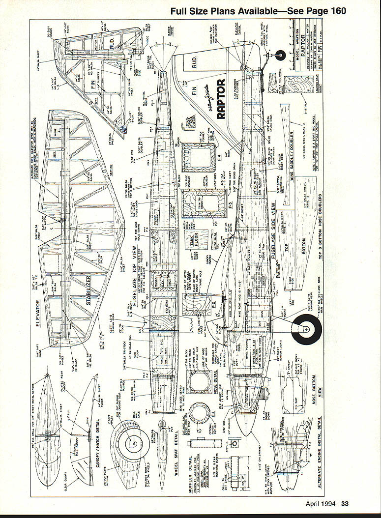
Drawings / Detail views
- Fuselage top view
- Fuselage side view
- Stabilizer
- Elevator
- Fin
- Rudder
- Canopy / hatch detail
- Wheel spat detail
- Muffler detail
- Nose bottom view
- Alternate engine install detail
- Top & bottom nose doublers
Transcribed from original scans by AI. Minor OCR errors may remain.

