
RB-59 Gladiator
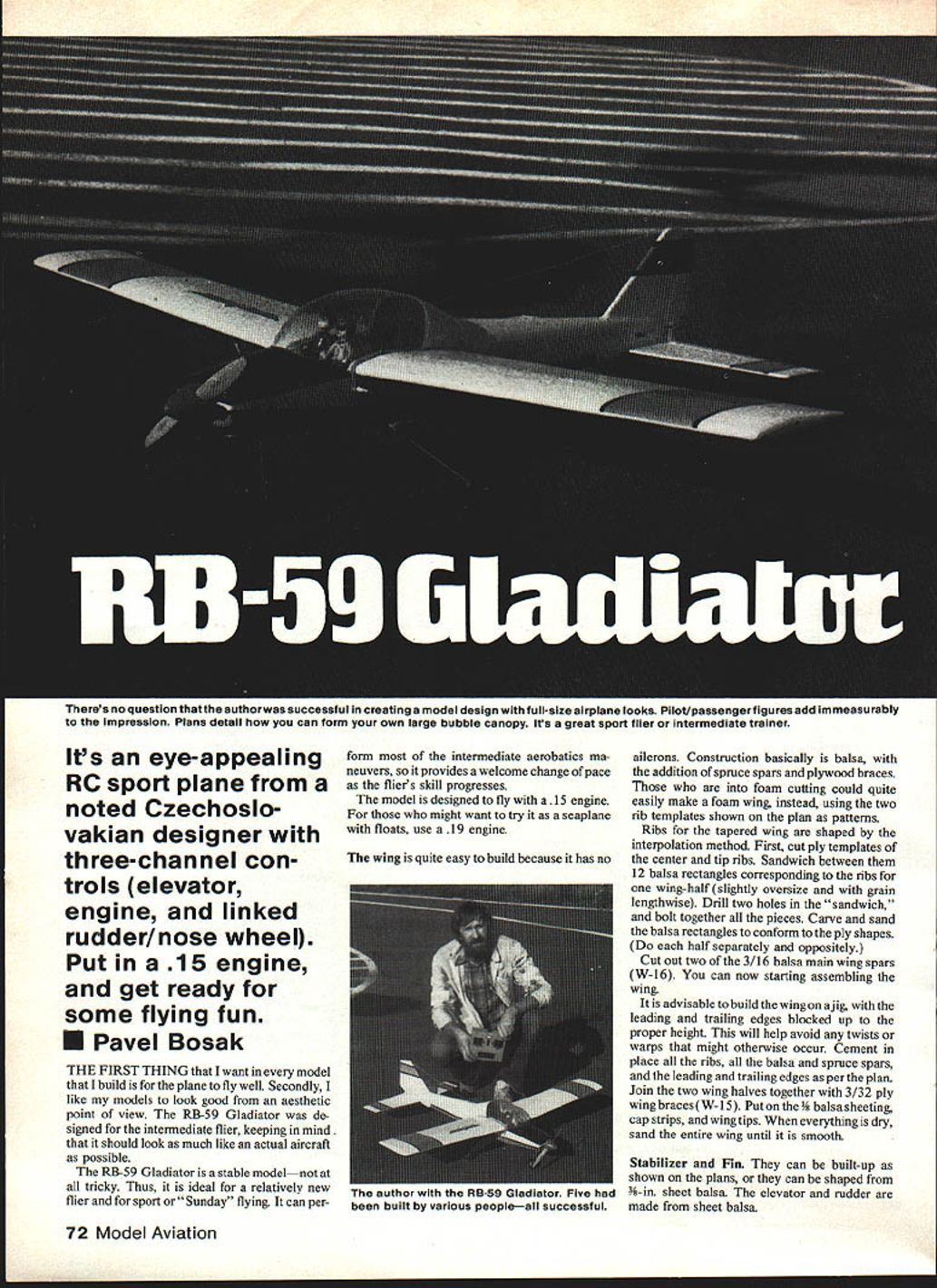
An eye-appealing R/C sport plane by noted Czechoslovakian designer Pavel Bosak. The RB-59 Gladiator was designed as an intermediate trainer/sport flier that looks as much like a full-size airplane as possible. It is stable and not tricky, making it ideal for relatively new fliers and for Sunday/sport flying, yet it can perform most intermediate aerobatic maneuvers.
- Designer: Pavel Bosak
General characteristics
- Controls: three-channel — elevator, engine (throttle), and linked rudder/nose wheel (steerable).
- Recommended power: .15 cu in engine (use .19 cu in if converting to floats/seaplane).
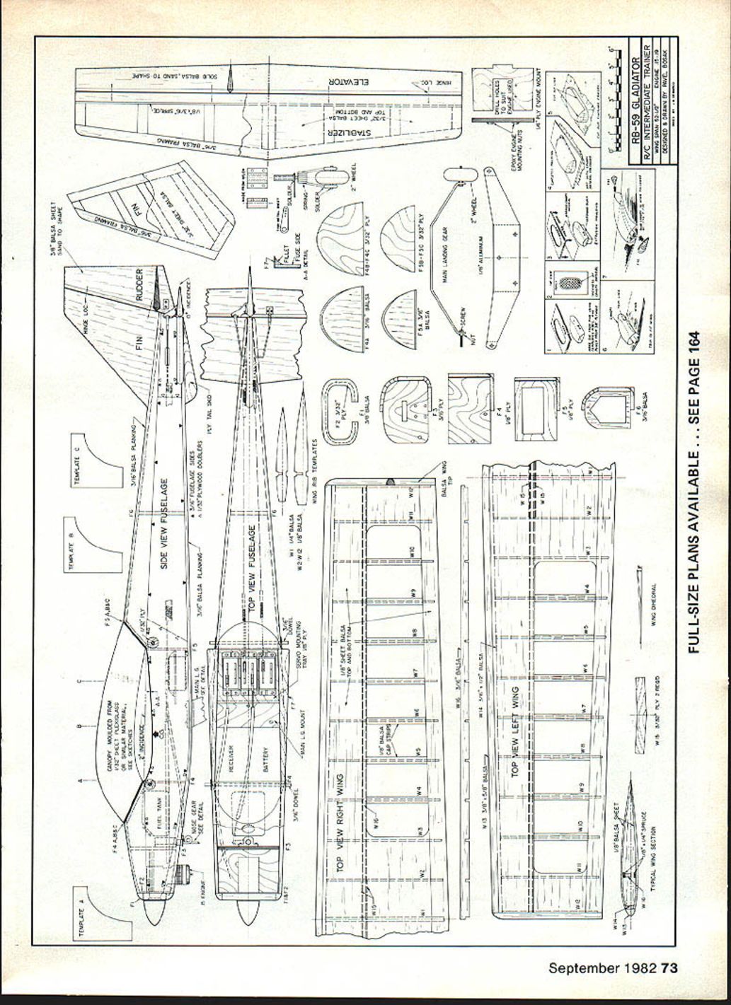
- Construction: primarily balsa with spruce spars and plywood braces; foam wings are also feasible using the rib templates on the plans.
- Features: large bubble canopy (plans show how to form it), cockpit details and pilot/passenger figures greatly enhance realism.
Wing
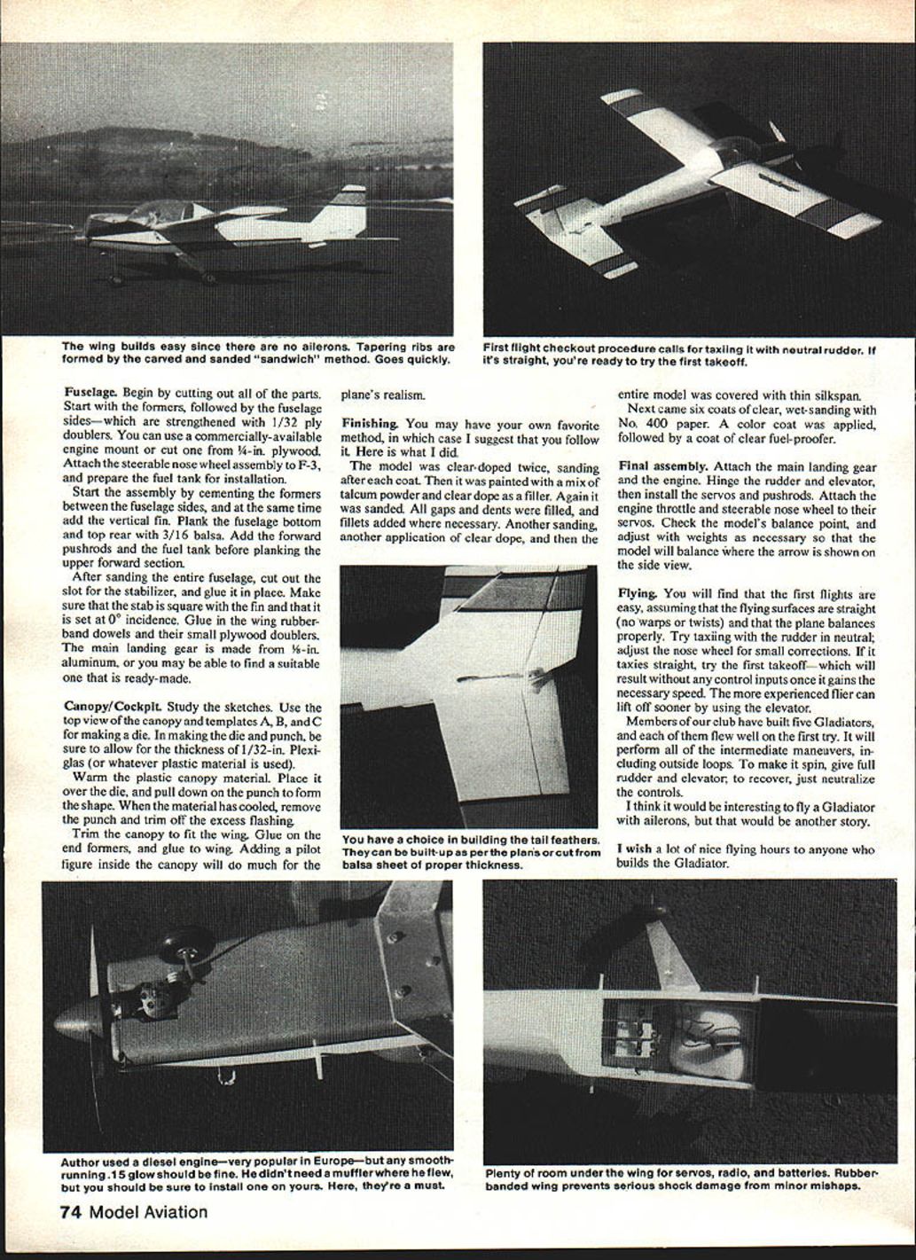
The wing has no ailerons, making it straightforward to build. Ribs are tapered and formed by the interpolation method.
Building the ribs (interpolation method)
- Cut plywood templates for the center and tip ribs.
- Prepare 12 balsa rectangles (slightly oversize, grain lengthwise) for one wing half.
- Sandwich the balsa rectangles between the plywood templates, drill two alignment holes through the sandwich, and bolt the pieces together.
- Carve and sand the balsa rectangles to match the plywood templates (do each wing-half separately and oppositely).
- Cut two main wing spars (W-16) from 3/16-in. balsa.
Wing assembly
- Build the wing on a jig with the leading and trailing edges blocked to the proper height to prevent twists or warps.
- Cement ribs in place along with the balsa and spruce spars, and install the leading and trailing edges per the plan.
- Join the two wing halves with 3/32-in. plywood wing braces (W-15).
- Apply 3/32-in. balsa sheeting, cap strips, and wing tips.
- When dry, sand the entire wing smooth.
Note: Foam builders can use the two rib templates from the plans as cutting patterns.
Stabilizer and Fin
- Can be built-up as shown on the plans or shaped from 3/16-in. sheet balsa.
- Elevator and rudder are made from sheet balsa.
- Ensure the stabilizer is square and set at 0° incidence relative to the fin.
Fuselage
Preparation and parts
- Cut out all parts, starting with formers.
- Strengthen fuselage sides with 1/32-in. plywood doublers.
- Use a commercially available engine mount or cut one from 1/4-in. plywood.
- Attach steerable nose wheel assembly F-3.
- Prepare the fuel tank for installation.
Assembly sequence
- Cement formers between fuselage sides; add the vertical fin during this stage.
- Plank the fuselage bottom and top rear with 3/16-in. balsa.
- Install forward pushrods and the fuel tank before planking the upper forward section.
- Sand the entire fuselage, then cut the slot for the stabilizer and glue it in place, ensuring it is square.
- Glue in wing rubberband dowels and small plywood doublers.
- Install the main landing gear (typically made from 1/8-in. aluminum, or a ready-made gear may be used).
Canopy / Cockpit
- Study the canopy sketches and use top-view templates A–C for the die.
- Allow for the thickness of 1/32-in. Plexiglas (or chosen plastic) when making the die and punch.
- Warm the plastic canopy material, place it over the die, and pull down with the punch to form the shape.
- After cooling, remove the punch, trim flashing, and fit the canopy to the fuselage.
- Glue end formers and glue the canopy in place.
- Add cockpit details and pilot/passenger figures to greatly enhance the model’s appearance.
Finishing
Suggested finishing sequence (one recommended method)
- Apply two coats of clear dope, sanding after each coat.
- Fill small gaps and dents; apply filler (example: talcum powder mixed with clear dope) and sand smooth.
- Apply another coat of clear dope and cover the model with thin silkspan.
- Apply six coats of clear dope, wet-sanding with No. 400 paper between coats.
- Apply color coat(s) as desired, then a final coat of clear fuel-proofer.
Follow your preferred finishing method if different.
Final assembly
- Attach main landing gear and engine.
- Hinge rudder and elevator; install servos and pushrods.
- Connect engine throttle and steerable nose wheel to their servos.
- Check the model's center of gravity and adjust with ballast as necessary so the plane balances at the location shown on the side-view plan.
Flying
- First flights are easy if flying surfaces are straight (no warps/twists) and the model is properly balanced.
- Taxi the model with the rudder neutral and adjust the nose wheel for small directional corrections.
- If it taxis straight, attempt takeoff; the model should lift off without control input once at flying speed. Experienced fliers can lift off sooner using elevator input.
- The Gladiator performs all intermediate maneuvers, including outside loops. To induce a spin give full rudder and elevator; recovery is by neutralizing controls.
- Club members have reported successful first flights on several Gladiators.
Final note: It would be interesting to try a Gladiator with ailerons, but that is a separate modification. Good flying hours to anyone who builds the Gladiator.
Transcribed from original scans by AI. Minor OCR errors may remain.

