
RC to CL B-24
By Dick Byron
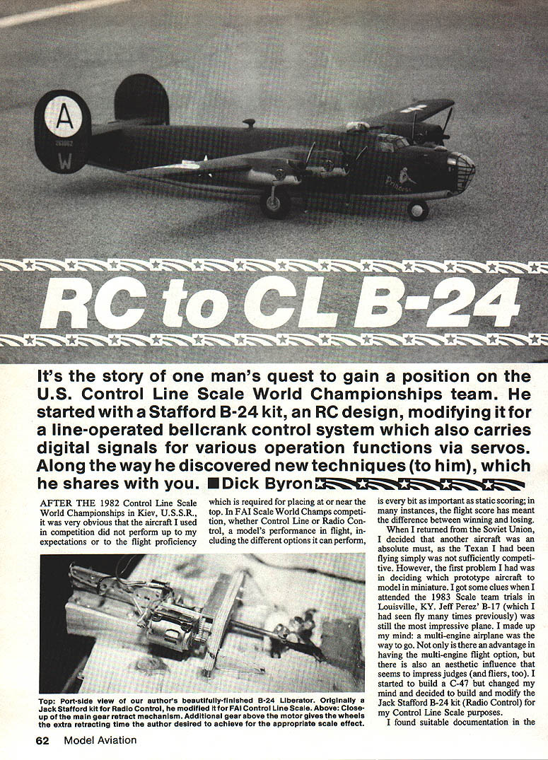
It's the story of one man's quest to gain a position on the U.S. Control Line Scale World Championships team. He started with a Stafford B-24 kit, an RC design, modifying it for a line-operated bellcrank control system which also carries digital signals for various operating functions via servos. Along the way he discovered new techniques (to him), which he shares here.
Background
After the 1982 Control Line Scale World Championships in Kiev, U.S.S.R., it was obvious that the aircraft I used in competition did not perform up to my expectations or to the flight proficiency required for placing at or near the top. At the FAI Scale World Championships—whether Control Line or Radio Control—a model's flight performance and options are every bit as important as static scoring; in many instances the flight score has meant the difference between winning and losing.
When I returned from the Soviet Union I decided another aircraft was an absolute must. The Texan I had been flying simply was not sufficiently competitive. The first problem was deciding which prototype to model in miniature. I got clues when I attended the 1983 Scale Team trials in Louisville, KY. Jeff Perez's B-17, which I had seen fly many times, was still the most impressive plane. I made up my mind: a multi-engine airplane was the way to go. Not only is there an advantage in having the multi-engine flight option, but the aesthetic influence seems to impress judges (and fliers, too).
I started to build a C-47 but changed my mind and decided to build and modify the Jack Stafford B-24 kit (originally for Radio Control) for Control Line Scale purposes.
Documentation and research
I found suitable documentation in Aerodata International No. 11 (Phillip J. R. Moyes, Visual Art Press Ltd., Oxford, England). The colored three-view drawings and other detailing in the book gave an ample, good rendition of the B-24. I also spent hours and a substantial amount of money obtaining other printed material showing construction techniques and detailing the full-size B-24 before beginning construction. I anticipated a major undertaking.
Converting RC to Control Line
Surprisingly, converting the RC model to CL was not as difficult as people seem to imagine. Because the Stafford B-24 has a foam wing, conversion was much simpler than it would have been with a built-up wing. A model of this size and weight requires a substantial control system. Having built CL stunters, I decided to use the same type of control system on the B-24—a nylon bellcrank pivoting on a threaded shaft with bearings through the center of the wing.
Instead of the usual small bellcrank, I used a Sig nylon bellcrank fitted over a 10-32 shaft, affording great strength for the bellcrank's diameter. Mounting the bellcrank sturdily at the center of gravity (CG) is the main objective while also ensuring it cleared the internal gadgets.
Deciding to use an electronic control system to operate the functions and options, the basic layout of the internal controls—engine throttles, retractable landing gear, operating flaps, rotating gun turret—had to be figured out before I could get very far.
Electronic control system
An old EK RC system would have been difficult to convert to operation through the control lines, so I sent the conversion to KRD Products, 5620 State Ave., Kansas City, KS 66101. Ken Wilson of KRD previously has done such rework for Mike Stott, Mike Gretz, Bill Hamey and others. He converted the system to direct servo control for a minimal charge. The system transmits control pulses through the control lines to a decoder in the model, thereby allowing proportional control of:
- rotating gun turret (in either direction),
- flaps,
- throttles,
- retractable landing gear.
Landing gear
Landing gear was a major problem: the plane had no way to couple both nose gear and main gear together to one servo, yet still have a removable wing. Fortunately I was able to purchase a very old wing-manufacturing retract mechanism to operate the nose gear unit; it seemed a workable solution. The servos I first tried simply did not have the power to retract the nose gear properly. Although noisy, a powerful unit does the job well.
The main gear required a different solution. The aircraft uses 4-inch-diameter wheels that are very heavy and are mounted on very long landing-gear legs. With this weight and leverage, a powerful system was needed. I used a Janco unit (built by Jack Stolly in Texas), though it required modification to work the gear in the time frame I desired. One modification was the addition of a nylon gear I manufactured from old servo gears. The added third gear allows about 20 seconds of retract time and produces roughly 35 lb. of power. In flight, with centrifugal force at work, about this much force is needed for the gear to retract properly and reliably.
After previous difficulties with retracting gears, I decided to use extra-large Du-Bro ball links and 1/8-inch piano wire for pushrods to achieve a very positive uplock and downlock. The system works very well and will retract the landing gear with minimal strain.
The landing gear has a separate battery pack to operate it, as does the rotating turret and the radio—for a total of three on-board battery packs.
Engine throttles and linkage
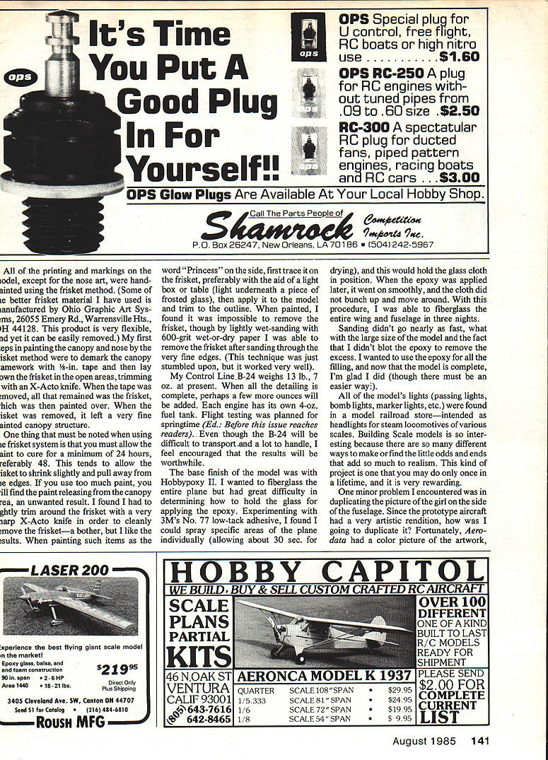
The throttles are operated by a retract servo for smooth transition and extra power (just in case). The linkage system between the bellcrank and the throttles seemed somewhat confusing at first, but by using Kraft engine mounts (which have a hole through the block) I was able to fabricate a bellcrank system to transfer the motion of the bellcranks above the wing to those in the bottom of the engine nacelles. This system easily works the throttles and the four O.S. .25s used to power the plane. Each engine has its own 4-oz. fuel tank.
Propellers
The propellers used were Zinger 10x7s, which were shaped, formed, and put together on the hubs. Making the props was a lot of work but well worth the effort, as non-scale props detract tremendously on a scale model.
Painting and markings
All of the printing and markings on the model, except for the nose art, were hand-painted using the frisket method. Some of the better frisket material I have used is manufactured by Ohio Graphic Art Systems, 26055 Emery Rd., Warrensville Hts., OH 44128. This product is very flexible, yet can be easily removed.
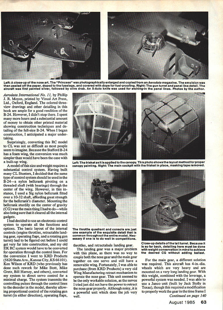
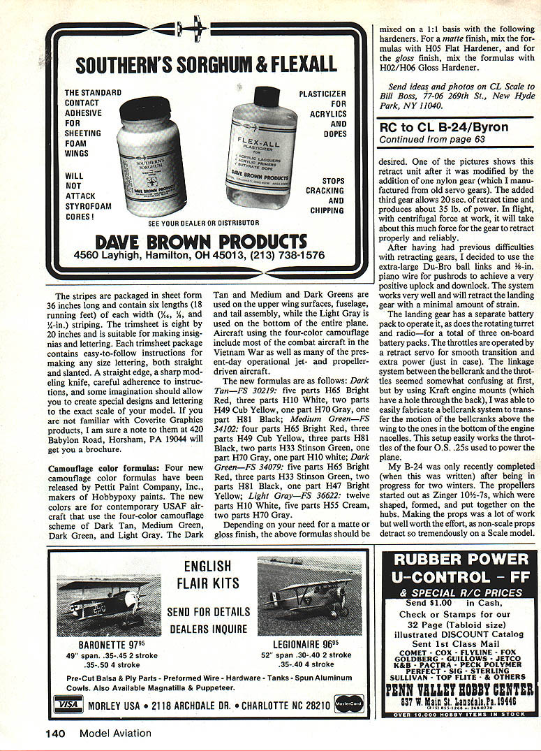
My first steps in painting the canopy and nose by the frisket method were to demark the canopy framework with 1/2-inch tape and then lay down the frisket in the open areas, trimming the frisket with an X-Acto knife. When the tape was removed, all that remained was the frisket, which was then painted over. When the frisket was removed, it left a very fine painted canopy structure.
Notes on the frisket method:
- Allow the paint to cure for a minimum of 24 hours, preferably 48. This allows the frisket to shrink slightly and pull away from the edges.
- Avoid using too much paint, which can pull away from canopy edges when removing the frisket.
- Tightly trim around the frisket with a very sharp X-Acto knife to cleanly remove it.
- For lettering (for example, "Princess"), first trace it on the frisket—preferably using a light box or frosted glass—apply to the model, trim to the outline, and paint. If the frisket is difficult to remove afterward, light wet-sanding with 600-grit wet-or-dry paper can remove the very fine edges.
Finishing and fiberglassing
The base finish of the model was Hobbypoxy II. I wanted to fiberglass the entire plane but had difficulty determining how to hold the cloth for laminating the epoxy. Experimenting with 3M No. 77 low-tack adhesive, I found I could spray specific areas of the plane individually (allowing about 30 seconds for drying) and this would hold the glass cloth in position. When epoxy was applied later, it went on smoothly and the cloth did not bunch up or move. With this procedure I was able to fiberglass the entire wing and fuselage in three nights.
Sanding took longer than expected due to the model's large size and my decision not to blot the epoxy to remove the excess; I wanted to use the epoxy for all the filling. Now that the model is complete, I'm glad I did, though there must be an easier way.
Lights and small details
All of the model's lights (position lights, bomb lights, marker lights, etc.) were found in a model railroad store—intended as headlights for steam locomotives of various scales. Building scale models is interesting because there are so many ways to make or find the little odds and ends that add realism. This kind of project may be a once-in-a-lifetime undertaking and is very rewarding.
One minor problem was duplicating the picture of the girl on the side of the fuselage. Since the prototype aircraft had an artistic rendition, who was I to duplicate it? Fortunately, Aerodata had a color picture of the artwork that I could use.
Weight and flight testing
My Control Line B-24 weighs 13 lb., 7 oz. at present. When all the detailing is complete, perhaps a few more ounces will be added. Flight testing was planned for springtime (Ed.: Before this issue reaches readers).
Competition plans
I'm looking forward to competing in the trials for the 1986 U.S. CL Scale Team to be held near Louisville, KY on August 23–25, 1985. (Ed.: Those desiring to enter the Scale Team Selection Program—either CL or RC—should note that the entry deadline is August 4, 1985, and the entry fee is $50. Contact John Guenther, RR 1, Box 715, Borden, IN 47106 for a packet of information and further details.)
To me the most rewarding part of this hobby/sport is achieving a level of competition in the thing you love the most—and being a member of the U.S. World Championships team and traveling with the team is a delicious frosting.
Transcribed from original scans by AI. Minor OCR errors may remain.

