
RC CO2 Indoor Taylorcraft
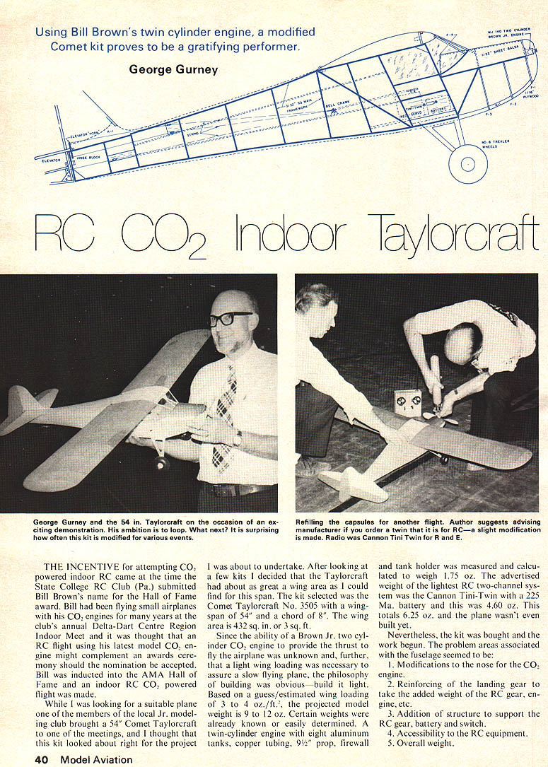
Using Bill Brown's twin cylinder engine, a modified Comet kit proves to be a gratifying performer.
George Gurney
THE INCENTIVE for attempting CO2 powered indoor RC came at the time the State College RC Club (Pa.) submitted Bill Brown's name for the Hall of Fame award. Bill had been flying small airplanes with his CO2 engines for many years at the club's annual Delta-Dart Centre Region Indoor Meet and it was thought that an RC flight using his latest model CO2 engine might complement an awards ceremony should the nomination be accepted. Bill was inducted into the AMA Hall of Fame and an indoor RC CO2 powered flight was made.
While I was looking for a suitable plane one of the members of the local Jr. modeling club brought a 54" Comet Taylorcraft to one of the meetings, and I thought that this kit looked about right for the project. After looking at a few kits I decided that the Taylorcraft had about as great a wing area as I could find for this span. The kit selected was the Comet Taylorcraft No. 3505 with a wingspan of 54" and a chord of 8". The wing area is 432 sq. in., or 3 sq. ft.
Since the ability of a Brown Jr. two cylinder CO2 engine to provide the thrust to fly the airplane was unknown and, further, that a light wing loading was necessary to assure a slow flying plane, the philosophy of building was obvious—build it light. Based on a guess/estimated wing loading of 3 to 4 oz./ft.2, the projected model weight is 9 to 12 oz. Certain weights were already known or easily determined. A twin-cylinder engine with eight aluminum tanks, copper tubing, 9½" prop, firewall and tank holder measured and calculated to weigh 1.75 oz. The advertised weight of the lightest RC two-channel system was the Cannon Tini-Twin with a 225 Ma. battery and this was 4.60 oz. This totals 6.25 oz. and the plane wasn't even built yet.
Nevertheless, the kit was bought and the work begun. The problem areas associated with the fuselage seemed to be:
- Modifications to the nose for the CO2 engine.
- Reinforcing of the landing gear to take the added weight of the RC gear, engine, etc.
- Addition of structure to support the RC gear, battery and switch.
- Accessibility to the RC equipment.
- Overall weight.
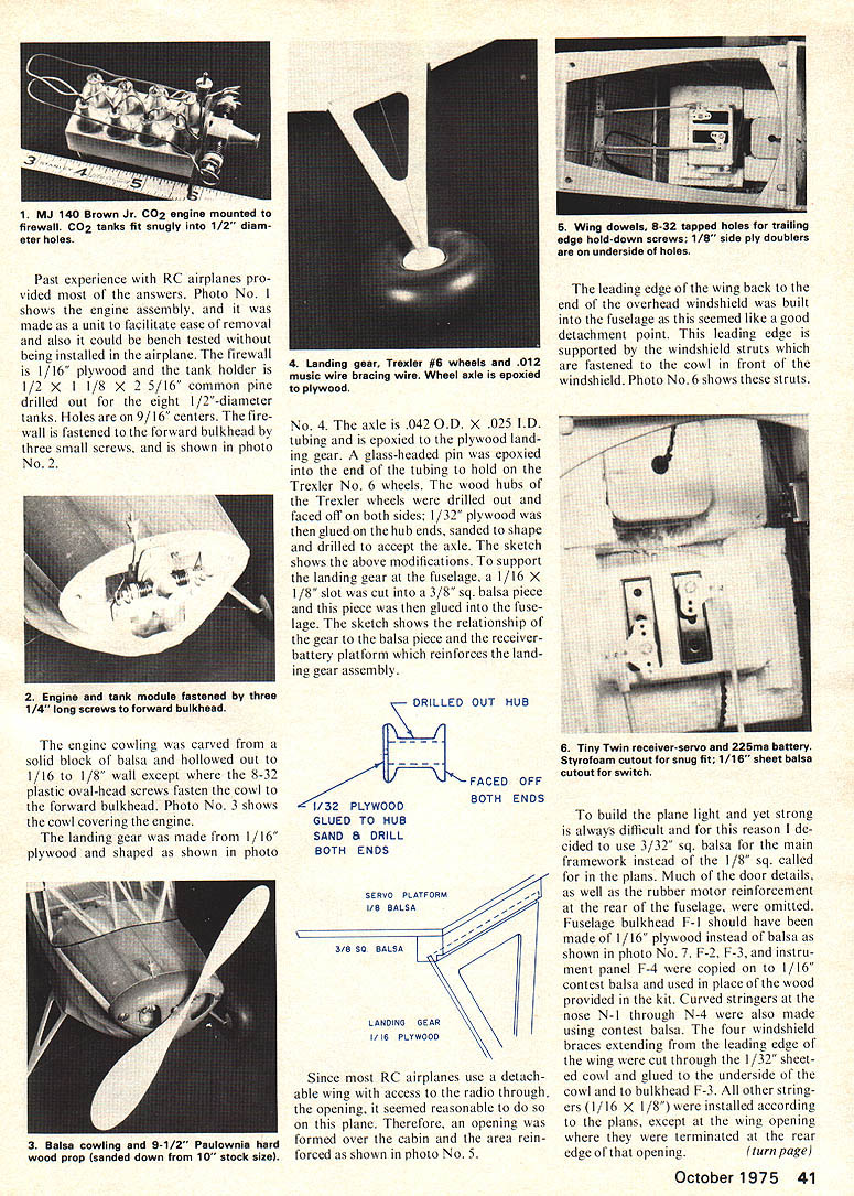
Photo No. 1 shows the engine assembly made a unit to facilitate ease of removal; it also could be bench tested before being installed in the airplane. Firewall is 1/16" plywood. Tank holder is 1/2" x 1 1/8" x 2 5/16" common pine drilled out for eight 1/2" diameter tanks. Holes are 9/16" on centers. Firewall fastened to the forward bulkhead with three small screws as shown.
The engine cowling was carved from a solid block of balsa and hollowed out to 1/16"–1/8" wall except where 8-32 plastic oval-head screws fasten the cowl to the forward bulkhead. Landing gear was made from 1/16" plywood and shaped as shown. The axle is 0.042" OD x 0.025" ID tubing epoxied to the plywood landing gear. A glass-headed pin was epoxied in the end of the tubing to hold Trexler No. 6 wheels. The wood hubs for the Trexler wheels were drilled out and faced off on both sides. 1/32" plywood was glued to the hub ends, sanded to shape and drilled to accept the axle. The sketch shows the above modifications to support the landing gear. A 1/16" x 1/8" slot was cut for a 3/8" sq. balsa piece; the piece was glued to the fuselage. The sketch shows the relationship of the gear and balsa piece. The receiver-battery platform reinforces the landing gear assembly.
Since RC airplanes use detachable wings, access to the radio through the opening seemed reasonable. Therefore an opening was formed over the cabin area and reinforced as shown. The leading edge, wing back end and overhead windshield built into the fuselage seemed like a good detachment point. Leading edge supported and windshield struts fastened to the cowl and front windshield. To build the plane light yet strong, and for reasons always difficult to explain, I decided to use 3/32" square balsa main framework instead of the 1/8" square called for in the plans. Many of the door details and the rubber motor reinforcement in the rear fuselage were omitted. Fuselage bulkhead F-1 should have been made of 1/16" plywood instead of balsa as shown. F-2 and F-3 instrument panels and F-4 were copied in 1/16" contest balsa and used in place of the wood provided in the kit. Curved stringers for the nose N-1 through N-4 were also made using contest balsa. Four windshield braces extending to the leading edge of the wing were cut from 1/32" sheet. Past experience with RC airplanes provided most of the answers. Photo No. 1 shows the engine assembly, and it was made as a unit to facilitate ease of removal and also it could be bench tested without being installed in the airplane. The firewall is 1/16" plywood and the tank holder is 1/2" x 1/8" x 2-5/16" common pine drilled out for the eight 1/2"-diameter tanks. Holes are on 9/16" centers. The firewall is fastened to the forward bulkhead by three small screws, and is shown in photo No. 2.
The engine cowling was carved from a solid block of balsa and hollowed out to 1/16" to 1/8" wall except where the 8-32 plastic oval-head screws fasten the cowl to the forward bulkhead. Photo No. 3 shows the cowl covering the engine.
The landing gear was made from 1/16" plywood and shaped as shown in photo No. 4. The axle is .042" O.D. x .025" I.D. tubing and is epoxied to the plywood landing gear. A glass-headed pin was epoxied into the end of the tubing to hold on the Trexler No. 6 wheels. The wood hubs of the Trexler wheels were drilled out and faced off on both sides; 1/32" plywood was glued on the hub ends, sanded to shape and drilled to accept the axle. The sketch shows the above modifications. To support the landing gear at the fuselage, a 1/16" x 1/8" slot was cut into a 3/8" sq. balsa piece and this piece was then glued into the fuselage. The sketch shows the relationship of the gear to the balsa piece and the receiver-battery platform which reinforces the landing gear assembly.
The leading edge of the wing back to the end of the overhead windshield was built into the fuselage as this seemed like a good detachment point. This leading edge is supported by the windshield struts which are fastened to the cowl in front of the windshield. Photo No. 6 shows these struts.
To build the plane light yet strong is always difficult and for this reason I decided to use 3/32" sq. balsa for the main framework instead of the 1/8" sq. called for in the plans. Much of the door details, as well as the rubber motor reinforcement at the rear of the fuselage, were omitted. Fuselage bulkhead F-1 should have been made of 1/16" plywood instead of balsa as shown in photo No. 7. F-2, F-3, and instrument panel F-4 were copied on 1/16" contest balsa and used in place of the wood provided in the kit. Curved stringers at the nose N-1 through N-4 were also made using contest balsa. The four windshield braces extending from the leading edge of the wing were cut through the 1/32" sheeted cowl and glued to the underside of the cowl and bulkhead F-3. All other stringers (1/16" x 1/8") were installed according to the plans, except at the wing opening where they were terminated at the rear edge of that opening. The problems associated with the wing were as follows:
1) Modifications required for one piece construction; 2) Wing Attachment; 3) Covering; 4) Weight.
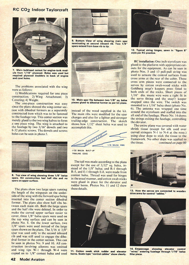
The one-piece construction was easy since the plans showed the wing center section with dihedral formers as a separately constructed item which was to be fastened to the fuselage top. This center section was merely glued to the two wing halves to form a one-piece wing. The wing is attached to the fuselage by two 3/16" dowels and two 8-32 plastic screws. The dowels and screws holes can be seen in photo 5.
The plans show two large spars running the length of the wingspan on the underside of the wing with the forward spar being inserted into the center section dihedral former. The plans also show half ribs between each main rib. Both the large spars and the half ribs were deleted. In order to make the curved upper surface easier to cover, three 1/8" balsa spars were used on the top wing surface and can be seen in photo No. 8. On the lower surface, two 1/8" spars were used instead of the large spars shown on the plans. The 3/16" x 3/8" spar was used only to the second inboard rib and was still used to engage the dihedral former in the center section. This can be seen in photos No. 9 and 10. All construction involving ailerons was omitted and wing tips W-1 through W-4 were copied onto 1/8" contest balsa and used instead of the wood supplied in the kit. The main ribs were modified for the spar changes and also for a lighter and stronger trailing-edge construction. The sketch shows how 1/32" sheet balsa was used to accomplish this.
The tail was made according to the plans except for the use of 3/32" sq. balsa, instead of the 1/8" balsa; and R-1 through R-5, and E-1 through E-8, were made from contest balsa. Thread was used for hinges in the usual manner, and cotton swab sticks were glued in place for the elevator and rudder horns. Photos No. 11 and 12 show these details.
RC installation: One inch styrofoam was glued to the platform with appropriate cutouts for the equipment. As can be seen in photo Nos. 5 and 13, pull-pull string was used to actuate the control surfaces from cross arms at the rear of the cabin. These cross arm pieces were connected to the servos by cotton swab–wood sticks with Goldberg snap'r keepers press fitted to both ends of the sticks. Short pieces of 1/16" dia. music wire were a tight fit in the servo fitting and the snap'r keeper snapped onto the wire. The switch was mounted to a 1/16" balsa sheet (photo No. 6). The antenna was wrapped one time around the styrofoam and stuffed into the aft end of the fuselage. Photo No. 14 shows the strings exiting the fuselage, controlling the elevator.
The entire plane was covered with water-shrink tissue (except for silk used over curved stringers N-1 to N-4 at the nose). Clear dope was used to stick the tissue to the framework. No other dope was applied to the tissue.
RC CO2: Indoor Taylorcraft
continued from page 42
The final weights were: Wing — 1.80 oz.; fuselage, empennage, control yokes, strings, styrofoam receiver and battery holder — 2.88 oz.; battery — 1.9 oz.; Radio Cannon Tini-Twin — 3.22 oz. Total weight — 11.35 oz. or 3.85 oz. per square ft.
Flying: I had no trouble balancing the plane since the radio weighed more than the plane, and a slight shift in the radio resulted in significant change in the C.G. location. After several trial flights and with the help of Bill Brown, we were able to get the plane off and fly several times around the Penn State Recreation Hall gymnasium. Bill had to change the timing on his engine to obtain more power and, of course, one wants to try CO2 indoor RC. He wouldn't specify its use for RC when ordering the engine. If one considers the indoor building process, it was not known whether little CO2 would even put the plane off the ground; the results were very gratifying. My goal was to do a loop and I think next year it will be done. Several mishaps occurred in the model, especially after hard landings. Hot Stuff glue would soften with heat and time. Bill has several ideas on how to extract more power out of the charge, and by no means was the propeller used to its fullest. Quality propellers with different pitches are not easily available. One tends to use large quantities of CO2; he should buy a 5- or 10-pound CO2 extinguisher and buy an adaptor from Bill Brown. The small CO2 sparklets would be expensive. Using the modified engine and a 10" wood prop cut down to 9½", the engine turned over from 2,200 to 2,400 rpm. This initial burst soon settled down to 1,400 to 1,500 rpm for the majority of the flight. The plane landed under power and could be taxied back to the "pit" area with rudder control.
Transcribed from original scans by AI. Minor OCR errors may remain.

