
RC Glider Caddy
A combination field box and glider carrier allows you to tote in one hand everything needed for flying—including the airplane.
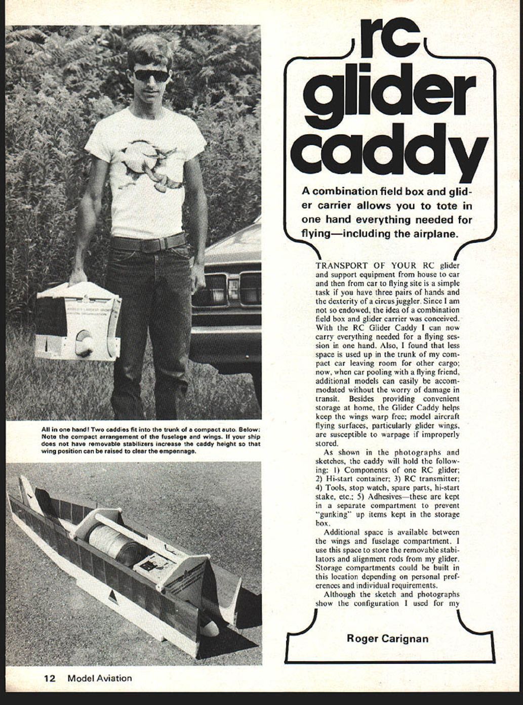
TRANSPORT OF YOUR RC glider and support equipment from house to car and then from car to flying site is a simple task if you have three pairs of hands and the dexterity of a circus juggler. Since I am not so endowed, the idea of a combination field box and glider carrier was conceived. With the RC Glider Caddy I can now carry everything needed for a flying session in one hand. Also, I found that less space is used up in the trunk of my compact car leaving room for other cargo; now, when car pooling with a flying friend, additional models can easily be accommodated without the worry of damage in transit. Besides providing convenient storage at home, the Glider Caddy helps keep the wings warp free; model aircraft flying surfaces, particularly glider wings, are susceptible to warpage if improperly stored.
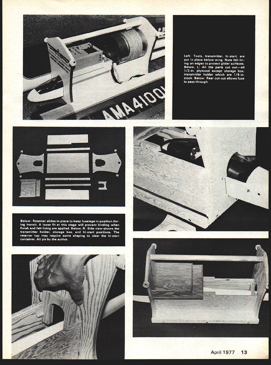
As shown in the photographs and sketches, the caddy will hold the following: 1) Components of one RC glider; 2) Hi-start container; 3) RC transmitter; 4) Tools, stop watch, spare parts, hi-start stake, etc.; 5) Adhesives—these are kept in a separate compartment to prevent "gunking" up items kept in the storage box.
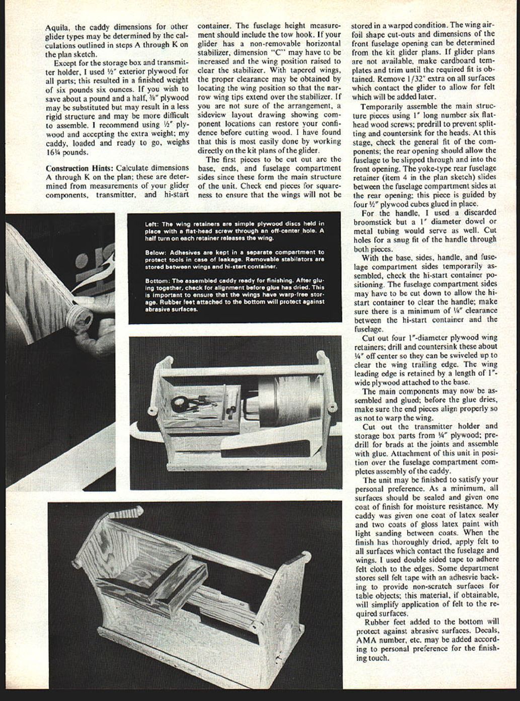
Additional space is available between the wings and fuselage compartment. I use this space to store the removable stabilators and alignment rods from my glider. Storage compartments could be built in this location depending on personal preferences and individual requirements.
Although the sketch and photographs show the configuration I used for my
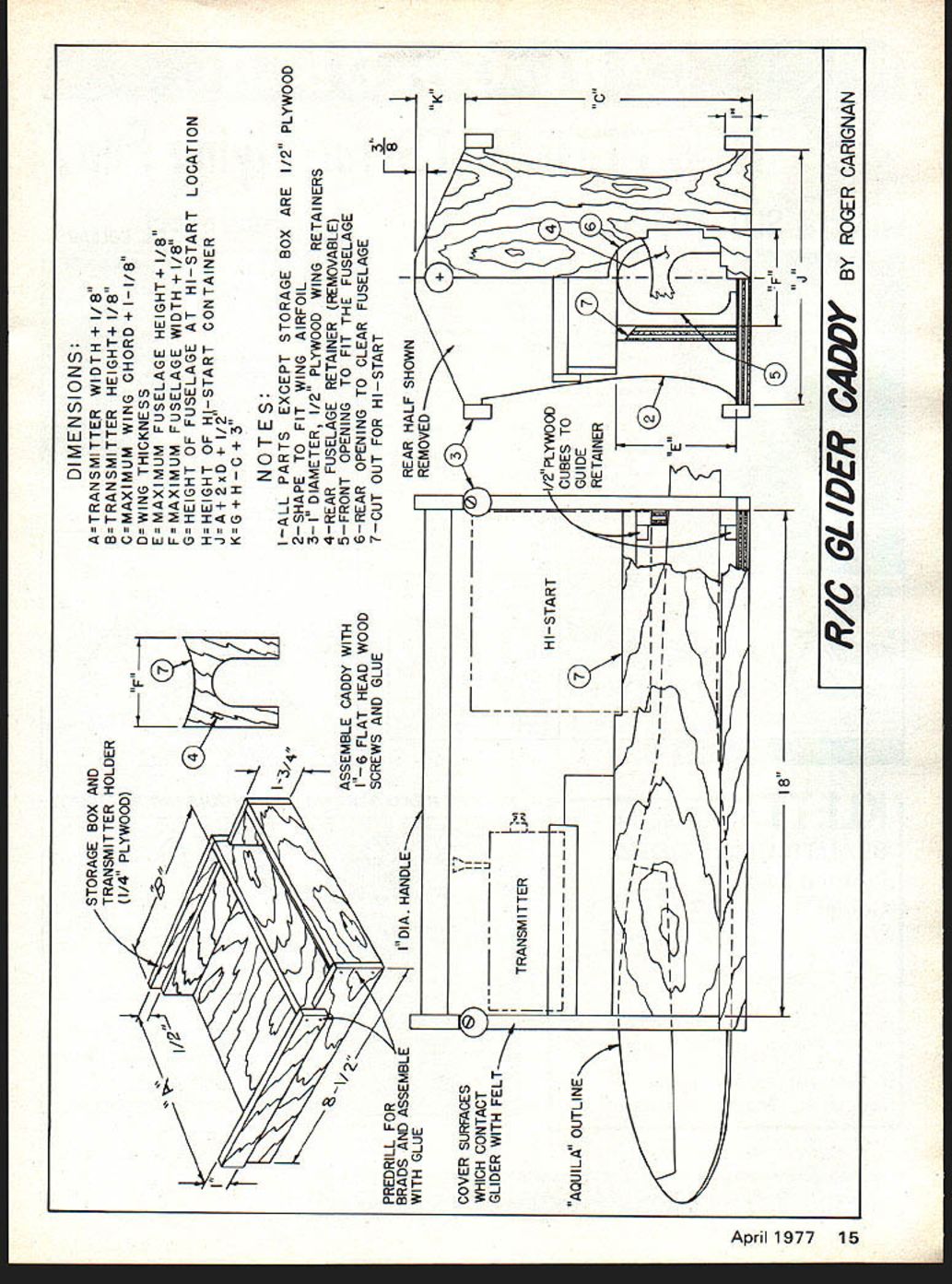
Roger Carignan Aquila, the caddy dimensions for other glider types may be determined by the calculations outlined in steps A through K on the plan sketch.
Except for the storage box and transmitter holder, I used 1/2" exterior plywood for all parts; this resulted in a finished weight of six pounds six ounces. If you wish to save about a pound and a half, 3/8" plywood may be substituted but may result in a less rigid structure and may be more difficult to assemble. I recommend using 1/2" plywood and accepting the extra weight; my caddy, loaded and ready to go, weighs 16 1/4 pounds.
Construction Hints:
Calculate dimensions A through K on the plan; these are determined from measurements of your glider components, transmitter, and hi-start container. The fuselage height measurement should include the tow hook. If your glider has a non-removable horizontal stabilizer, dimension "C" may have to be increased and the wing position raised to clear the stabilizer. With tapered wings, the proper clearance may be obtained by locating the wing position so that the narrow wing tips extend over the stabilizer. If you are not sure of the arrangement, a sideview layout drawing showing component locations can restore your confidence before cutting wood. I have found that this is most easily done by working directly on the kit plans of the glider.
The first pieces to be cut out are the base, ends, and fuselage compartment sides since these form the main structure of the unit. Check end pieces for squareness to ensure that the wings will not be stored in a warped condition. The wing air-foil shape cut-outs and dimensions of the front fuselage opening can be determined from the kit glider plans. If glider plans are not available, make cardboard templates and trim until the required fit is obtained. Remove 1/32" extra on all surfaces which contact the glider to allow for felt which will be added later.
Temporarily assemble the main structure pieces using 1" long number six flathead wood screws; predrill to prevent splitting and countersink for the heads. At this stage, check the general fit of the components; the rear opening should allow the fuselage to be slipped through and into the front opening. The yoke-type rear fuselage retainer (item 4 in the plan sketch) slides between the fuselage compartment sides at the rear opening; this piece is guided by four 1/8" plywood cubes glued in place.
For the handle, I used a discarded broomstick but a 1" diameter dowel or metal tubing would serve as well. Cut holes for a snug fit of the handle through both pieces.
With the base, sides, handle, and fuselage compartment sides temporarily assembled, check the hi-start container positioning. The fuselage compartment sides may have to be cut down to allow the hi-start container to clear the handle; make sure there is a minimum of 1/8" clearance between the hi-start container and the fuselage.
Cut out four 1"-diameter plywood wing retainers; drill and countersink these about 1/4" off center so they can be swiveled up to clear the wing trailing edge. The wing leading edge is retained by a length of 1"-wide plywood attached to the base.
The main components may now be assembled and glued; before the glue dries, make sure the end pieces align properly so as not to warp the wing.
Cut out the transmitter holder and storage box parts from 1/4" plywood; predrill for brads at the joints and assemble with glue. Attachment of this unit in position over the fuselage compartment completes assembly of the caddy.
The unit may be finished to satisfy your personal preference. As a minimum, all surfaces should be sealed and given one coat of finish for moisture resistance. My caddy was given one coat of latex sealer and two coats of gloss latex paint with light sanding between coats. When the finish has thoroughly dried, apply felt to all surfaces which contact the fuselage and wings. I used double sided tape to adhere felt cloth to the edges. Some department stores sell felt tape with an adhesive backing to provide non-scratch surfaces for table objects; this material, if obtainable, will simplify application of felt to the required surfaces.
Rubber feet added to the bottom will protect against abrasive surfaces. Decals, AMA number, etc. may be added according to personal preference for the finishing touch.
DIMENSIONS:
A - TRANSMITTER WIDTH + 1/8" B - TRANSMITTER HEIGHT + 1/8" C - MAXIMUM WING SPAN / 2 + 1-1/8" D - MAXIMUM WING CHORD AT HI-START LOCATION E - MAXIMUM FUSELAGE DIAMETER F - HEIGHT OF FUSELAGE AT CONTAINER G - HEIGHT OF HI-START CONTAINER H - WING SADDLE HEIGHT I - (not shown) J - (not shown) K = G + H + C + 3/8"
NOTES:
- ALL PARTS EXCEPT STORAGE BOX ARE 1/2" PLYWOOD.
- SHAPE OF PARTS FIT WING PROFILE.
- PLYWOOD WING RETAINERS.
- REAR FUSELAGE RETAINER (REMOVABLE).
- FRONT OPENING TO CLEAR FUSELAGE.
- CUT OUT FOR HI-START.
- REAR HALF SHOWN REMOVED.
AQUILA caddy dimensions — other glider types may be determined by calculations outlined steps through K plan sketch. Except storage box and transmitter holder, 1/2" plywood parts resulted in finished weight six pounds six ounces. If you wish to save about 1 pound, 1/8" plywood may be substituted; this may result in a less rigid structure and may be more difficult to assemble. I recommend using 1/2" plywood; accepting the extra weight the caddy loaded and ready to go weighs 16-1/4 pounds.
Construction Hints
Calculate dimensions through K plan determined measurements of glider components, transmitter and hi-start container. Fuselage height measurement should include tow hook. If the glider has a non-removable horizontal stabilizer, dimension C may have to be increased. Wing position may be raised to clear stabilizer. For tapered wings, proper clearance may be obtained locating wing position narrow so wing tips extend over stabilizer. Be sure arrangement shown in side view layout drawing showing component locations can restore confidence before cutting wood. I have found this easily done working directly from kit plans or glider.
First pieces cut out are base, ends and fuselage compartment sides since these form the main structure unit. Check end pieces for squareness; ensure wings will be stored without warped condition. Wing airfoil shape cut-outs dimensions and front fuselage opening can be determined from kit glider plans. Kit glider plans are available; make cardboard templates and trim until required fit is obtained. Remove 1/32" extra surfaces which contact glider to allow felt to be added later.
Temporarily assemble main structure pieces using 1 long number six flathead wood screw; predrill to prevent splitting and countersink heads. At this stage check general fit of components. Rear opening should allow fuselage to be slipped through front opening. Yoke-type rear fuselage retainer (item 4, plan sketch) slides between fuselage compartment sides. Rear opening piece is guided by four wood cubes glued in place. Handle used was a discarded broomstick diameter dowel; metal tubing would serve well.
Cut holes for a snug fit of handle through both base sides and handle/fuselage compartment sides. With temporarily assembled unit, check hi-start container positioning. Fuselage compartment sides may have to be cut down to allow hi-start container to clear handle. Make sure minimum 1/8" clearance between hi-start container and fuselage.
Cut out four 1"-diam. plywood wing retainers; drill and countersink about center so they can be swiveled up clear of wing trailing edge. Wing leading edge retained by 1" wide plywood attached to base.
Main components may now be assembled and glued; before the glue dries make sure end pieces align properly so as not to warp the wing.
Cut out transmitter holder and storage box parts from 1/4" plywood; predrill for brads at joints and assemble with glue. Attachment of this unit in position over the fuselage compartment completes assembly of the caddy.
Cover surfaces which contact glider with felt. Predrill for brads and assemble storage box with glue.
Assemble caddy with 5/8" flat head wood screws and glue. Add 1" diameter handle.
Transcribed from original scans by AI. Minor OCR errors may remain.

