
RC Seagull
Gus Munich
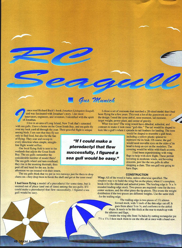
I once read Richard Bach's Jonathan Livingston Seagull and was fascinated with Jonathan's story. Like most innovators, engineers, and inventors, I identified with the spirit of Jonathan.
I live on the Great South Bay, Long Island, New York, in an area saturated with seagulls. They fly over my backyard year-round. Their graceful flight is unique among birds — I am sure they fly not only to find food but also for the fun of flying. They soar and swoop in every direction when a simple straight-line flight would suffice.
Our local flying field borders the wetlands that adjoin the Great South Bay. The seagulls outnumber our model fliers. They wheel and turn overhead, rise in morning thermals, peel off toward the sea, and return in the afternoon. The seagulls think our runways are for dropping clams — they drop them to break the shell and get at the meat!
I had been flying a pterodactyl model, but it seemed out of place among the seagulls. If I could make a pterodactyl that flew successfully, I figured a seagull would be easy. I matched moments (airfoil, nose moment, tail moment, target weight, power plant, and center of gravity) to a .20-sized model I had flown for years. That took much of the guesswork out of the design.
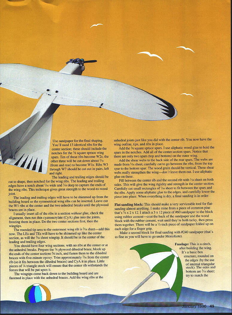
What was new? The wing would have dihedral, anhedral, and contours to look more "gull-like." The tail would spread like a gull's tail feathers for landing. The nose would resemble a gull head, including a yellow plastic spinner to represent the beak and removable eyes on the sides. The covering would be white with black accents.
I had been experimenting with wing flaps for slow flight. These permit hovering in moderate winds and hovering descents, just like the seagulls after dropping a clam. This seagull would have flaps.
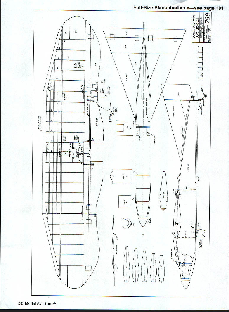
Construction
Wing
- All wood is balsa unless otherwise specified. Build the wing flat on the plans; when complete, break it for the dihedral and anhedral joints.
- Leading edge (LE): 5/8" x 3/4" rounded leading-edge stock. Use two pieces — one for the center sections and one for the tip pieces to even out weight if the pieces differ. Use the same trick for the trailing edge.
- Trailing edge (TE): two pieces of 1/4" aileron-formed stock, with 1/4" of the thin edge cut off. It goes from about 3/8" to 1/4" and conforms to the airfoil shape. It needs to be this thick at the rear to match the ailerons and flaps.
- Ribs: make wing ribs from 1/16" balsa by cutting rectangular pieces 7-1/2" x 1-1/2", stack them and cut all ribs at once with a band saw. Use sandpaper for final shaping.
- You will need 13 identical ribs for the center section; these should include notches for 1/8" square spruce spars.
- Ten ribs become W2s; the other three are cut down about 3/16" (front and rear) to become W1s.
- Ribs W3 through W7 should be cut out in pairs, left and right.
- Notching: cut the LE and TE to shape, then notch for the ribs. Notch about 1/16" wide and 1/16" deep to capture rib ends — this gives great wood-to-wood joint strength.
- Assembly: shim the LE and TE from the building board so symmetrical ribs can be inserted. Leave out the W1 ribs at the center and at the two anhedral breaks until the plywood braces are in place.
- Insert ribs dry, check alignment, then run thin cyanoacrylate (CyA) into joints to freeze them in place. Do the two center sections first, then the wingtips.
- Tip area: rounded tip area to the outermost rib is 3/16" sheet — add this now. Shim LEs, TEs, and the 3/16" sheet tip so it sits centered between LE and TE.
- You should have four wing sections with no ribs at the center or at the anhedral breaks. Prepare 1/8" plywood dihedral braces, block up the ends of the center sections 5/8", and fasten them to the dihedral braces with five-minute epoxy. Trim approx. 3/16" from the center rib (so it fits between the dihedral braces) and CyA it in place. Small pieces of 1/4" triangle stock will ensure the center rib withstands forces.
- Attach anhedral braces, add wing ribs at anhedral joints as before. Add 1/8" x 5/8" square spruce spars, glued with aliphatic glue into notches. Add all center section spars — note only two spars (top and bottom) on the outer wing.
- Shear webs: add shear webs to the back side of the rear spars from 1/16" sheet cut between ribs, top spar to bottom spar. Grain should be vertical. These strengthen the wing — don't omit them. Use aliphatic glue.
- Fill between center rib and second rib with 1/16" sheet on both sides for center-section rigidity. Cut small rectangles of 1/16" sheet to fit between spars and ribs, glue edges, lower into place, and sand when dry.
- Sanding blocks: make a flat sanding block from pine (3/4" x 2" x 12") with #60 sandpaper attached using rubber cement for rough sanding; make a second block with #240 sandpaper for final sanding before covering.
Ailerons, Torque Tube, and Flaps
- Aileron servo: mount by cutting a rectangular hole in the center-bottom wing surface. Mount plywood plates on the 1/16" wing surface for the servo screws.
- Aileron linkage: the horn linkage must couple torque out to the ailerons and account for dihedral/anhedral mismatch. Use 3/32" Goldberg aileron horn sets in the center of the wing, but modify outer ends to mate with 3/16" diameter aluminum-tubing torque rod.
- Cut the end wire normally inside the plastic tube about 1-1/2" from the bend, discard the plastic tube, bend the wire in a zig-zag so it slides into the aluminum tube, coat with five-minute epoxy, and slide it in. Make a similar wire end for the other tube end. This gives an aluminum-tube extension with a wire end to overcome plane difference between the aileron-horn extension and the hinge line.
- Hinge and mount ailerons: aluminum tubes rotate in sheet-aluminum hinges. I use .010" aluminum flashing folded around the tubing to give tabs inserted into slots in the wing. Tin-can brackets connect the aileron to the torque-rod ends. Use a Z-bend at the servo and Du-Bro nylon Kwik-Links at the aileron horn end for adjustment.
- Flaps: add the flap servo under the lug of the aileron servo, flat on its side. Mount 1/8" plywood blocks supported by balsa blocks for the servo screws. Socket-head screws and a ball-head hex driver make mounting easier.
- Use a round servo wheel with opposing Du-Bro E-Z Connectors mounted with nylon washers. Two flexible braided-steel wires inside plastic guides (Sullivan Flex Push cable, .056" diameter) make the flap linkages.
- The two cables pass inside the wingroot (wingtip-to-wingtip direction), then curve 90° to exit the underside for connection to flap control horns. Fasten the plastic sheath at both ends to transmit servo movement fully.
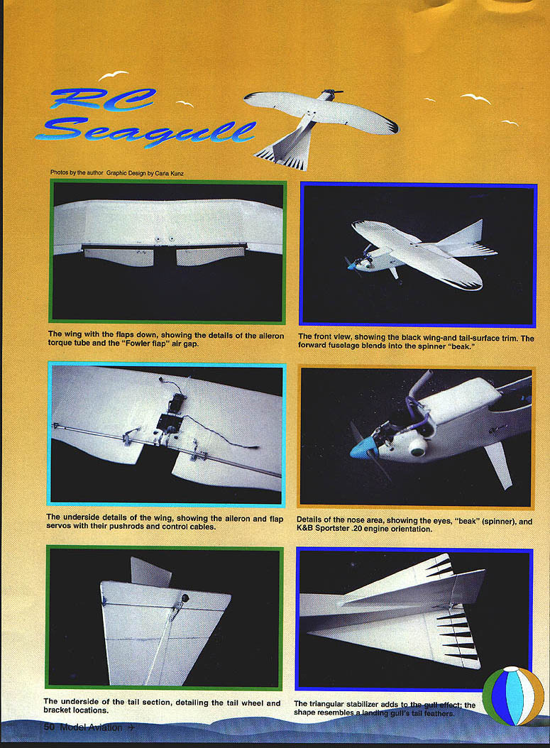
- Mount flaps using Robart Super Hinge Points with steel pins. Place hinge point below the aileron tube so flaps clear the tube and create a wide gap when flaps are down. This gap allows air to bleed and flow over the flaps, producing an action similar to Fowler flaps without complex linkages. There should be no pitch change from flaps-up to flaps-down with this arrangement.
- Use large Du-Bro T-style nylon control horns on flaps. Left and right flex cables should connect to opposite sides of the servo wheel so both cables push or pull as the servo turns. Flaps should deflect about 50°.
- Finalize: slotted exit holes help during setup until cable runs move smoothly. Secure components with fillets of balsa dust or microballoons and CyA. Hinge points fit into drilled holes and are fastened with CyA when action is smooth.
Alignment and Hardware
- Check wing-tail alignment by measuring from each wingtip to the rudder hinge line; when measurements match, wing alignment in that dimension is correct. Then sand and check alignment with the elevator — wing-to-elevator alignment is important to avoid odd maneuvers.
- Drill through wing and fuselage blocks with a #7 drill for wing bolts. Drill perpendicular to the wing top surface because holes in blocks will be slanted. Add a 1/16" plywood plate under the wing-bolt area and glue in place.
- Use 1/4" diameter blind nuts in fuselage blocks. Use washers and locknuts on wing-bolt hardware and a little Loctite on the locknuts.
Fuselage
- Basic structure: a box structure rounded on the edges using internal triangular stock. Sides and bottom are 3/16" sheet. Try to match underside details, servos, pushrod routing, tail-wheel bracket locations, triangular stabilizer shape and reserve flap, eyes, beak, and look for stiffness. Sides and bottom should be fairly hard.
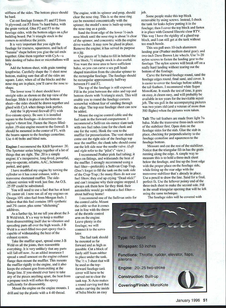
- Formers: cut out fuselage formers F1, F2 and F3. F1 is 1/8" plywood; F3 is 3/16" hard balsa with grain vertical (in other places F3 is given as 1/16" hard balsa — use the thickness appropriate to your plans). Glue F2 and F3 to fuselage sides and bottom edges flat on the building board. Put angle stock in the corners to reinforce joints — this is critical for trueness and squareness; lack of this produces a banana shape.
- Tail ends: before gluing tail ends together, glue components with CA and add a little balsa dust and microballoons if needed.
- Bottom and nose: add the bottom sheet with grain lengthwise. Carefully shape the nose bottom, keeping sides square. Later nose-ring blocks will be placed for carving the nose shape. The lower nose 1/2" sheet should have straight sides as shown in the top view of the plans. Slide the top and bottom sheets together and glue with CyA when the fit looks perfect.
- Firewall: add the 1/8" plywood firewall (F1) with five-minute epoxy, ensuring it is installed square to determine the engine thrust line. Fasten the Hayes-filled nylon .19-size engine mount to the firewall with 4-40 bolts and blind nuts; center it between F1 beams and square to the fuselage centerline.
- Nose build-up: the spinner and prop should clear the nose ring so the nose ring can be mounted concentrically. Using the engine as a jig, sand the front edge of the lower 1/2" nose block until the nose ring is about 1/8" rear of the spinner and concentric with the engine drive washer, then glue in place. Remove the engine. Use 1/2" balsa pieces and 1/4" triangle stock as filler behind the nose block to give sufficient balsa for carving a seagull-head-shaped transition from the circular spinner to the rectangular fuselage. The fuselage should be rectangular approximately halfway between F1 and F2.
- Top joint: fill the joint between sides and top/bottom sheets with 1/8" triangle stock so you can round fuselage corners without sanding through edges. Add the top rear fuselage sheet.
- Engine bay sealing and reinforcement: add plywood one-inch-diameter reinforcement where bolts bear. I use white K&B epoxy paint to seal the engine compartment, tail fillets, and anything not covered with MonoKote.
Tank, Controls, and Gear
- Fuel tank: mount a Sullivan six-ounce slant tank with two fuel tubes (one for the clunk and one for the vent). Hook the vent to the muffler for pressurization. The vent should exit the right side of the fuselage just forward of the muffler; the clunk tube should exit the left side near the needle valve (left and right refer to the pilot's view).
- Use Prather pink fuel tubing — it stays on fittings and withstands muffler heat. Use a fuel filter — preferably a Sullivan Crap-Trap (fill the tank on the tank side of the Crap-Trap).
- Control cable: I recommend a Sullivan servo unit for the throttle control cable. Mount the cable to come out in line with the throw of the throttle control arm on the engine, leaving plenty of cable to connect to the servo later.
- Tank mounting: mount the tank as far forward and as high as possible. Cut a block of fairly stiff foam rubber to place under the tank. Carve a recess in the 1/2" x 3" top cover to clear the tank using an X-Acto round carving tool. Some make the top block removable with screws; I seal the top block with RTV after checking the tank for leaks so you still have access.
- Landing gear: use 10" aluminum landing gear (Prather medium dual gear) and two-ounce Dave Brown Lite wheels. Fasten landing gear with 1/4-20 nylon screws — nylon screws will break off in a hard landing without tearing out the fuselage bottom.
- Tail wheel: add a Du-Bro filled-nylon tail wheel bracket. The tail wheel should line up with the rudder and trail backward about 45°. A simple tin-can metal bracket can tie the tail wheel to the rudder.
Engine
- Recommendation: K&B Sportster .20 — simple, inexpensive, long-lived, powerful, easy to operate, reliable, Schnuerle-ported and relatively quiet. An O.S. .25 FP can be substituted; use fuel with at least 2% castor oil.
- Fuel: I run engines on Omega 10% nitro fuel (Morgan fuels — believed to contain roughly 18% synthetic, 2% castor plus slickening additives).
- J-B Weld trick: to keep the muffler from letting parts fall off due to vibration, disassemble the muffler, spread J-B Weld (steel-filled two-part epoxy) on joints, reassemble, and the epoxy resists exhaust heat. Add a small amount to the engine exhaust flange and muffler mounts to mount the muffler rigidly and prevent exhaust leaks. If disassembly is needed later, heat with a propane torch to soften the epoxy.
- Mounting: drill and tap plastic engine mounts for 4-40 threads if necessary. Ensure spinner and prop clear the nose ring; mount the engine square to the firewall. Use angled stock pieces for filler behind the nose block if carving is desired.
Tail
- Tail feathers: make tail surfaces from light 3/16" balsa. Make the transverse 3" section of the stabilizer first. Cut open slits on the fuselage sides for stabilizer sides to fit. Glue the stab in place, checking for perpendicularity to the fuselage centerline and that it is square to the fuselage bottom.
- Completing stabilizer: measure and cut the rest of the stabilizer. Note triangular fill-in grain runs along the edge. Use a 3" sheet held below the fuselage to mark and sand for a perfect fit; use leftover pointy ends to make the second side. Fill triangular openings similarly.
- Covering prep: cover fuselage sides with MonoKote. You can't glue to MonoKote, so remove a 3/16" x 13" strip of covering where triangular fill-in will be glued.
- Fillets: make small fillets of microballoons and CyA for uneven joints if needed. For the vertical stabilizer, use 1/4" triangular stock as a fillet — remove MonoKote on the top deck accordingly.
- Control surfaces: make and cover elevator and rudder from 3/16" sheet. Cover stabilizer and fin, hinge surfaces, and make flaps and ailerons.
- Hinges: hinge rudder and elevator to the fuselage. Sig Easy Hinges are trouble-free and easy to install; use a #11 blade and ensure hinge slots center the hinge parts.
- Final: fillet and finish joints, install tail hardware and check control surface movement.
Covering and Finish
- Covering: I recommend White Super MonoKote — durable, easy to apply and repair, and likely to be available long-term.
- Trim and markings: seagulls in the area vary from dull gray to pure white with black accents on wingtips. Add black accents on top and bottom of wingtips and black tail triangles to simulate feathers using black iron-on MonoKote. Avoid temporary trim sheets; the iron-on will last.
- Eyes: I used 39mm craft-store frog eyes attached to MonoKote with silicone glue; they have movable pupils that always look down and read well at distance. Alternatively use the largest flat eyes available.
- Color alternative: if you don't see seagulls where you live, cover the model with gray MonoKote, add black accents and claws, and call it a hawk.
Flying and Setup
- Control throws (starting points):
- Aileron: ±1/2"
- Elevator: ±1"
- Rudder: ±1-1/4"
- Adjust to taste; variable flap settings are helpful if your radio supports them.
- Handling: the design is docile and controllable and capable of any maneuver an average pilot can handle. The trick is to fly the model like a seagull.
- Flaps: with flaps down the seagull is more stable and easier to control, even practically hovering.
- Touch-and-gos are fun with this model — instead of a bomb drop you might add a clam drop!
Good luck with your Seagull. If you wish to write, include a self-addressed stamped envelope if you would like a reply.
Gus Munich 24 Skipper Dr. W. Islip, NY 11795
Transcribed from original scans by AI. Minor OCR errors may remain.

