

RC Strider
Dick Birdwell
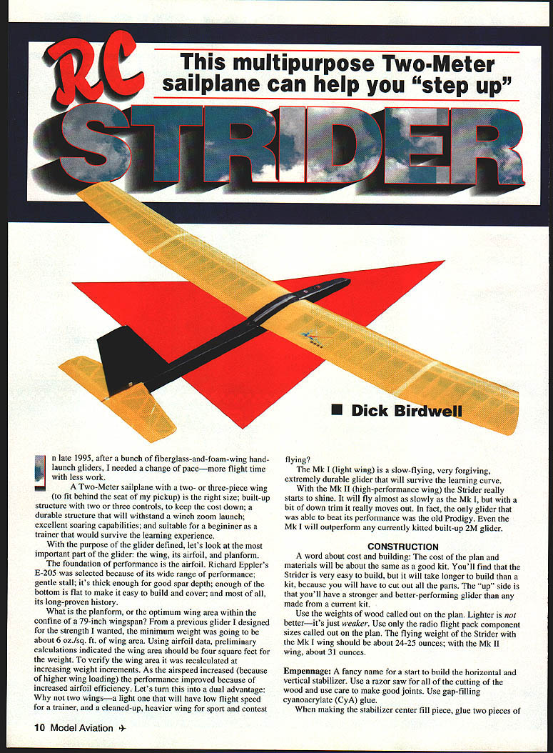
This multipurpose Two-Meter sailplane was designed to help pilots "step up" from handlaunch and simple trainers to a durable, higher-performance glider with reasonable building effort. Goals included a two- or three-piece wing to fit behind a pickup seat, a built-up structure with two or three controls to keep cost down, durability for winch launches, excellent soaring capability, and suitability as a trainer that will survive the learning experience.
The wing, its airfoil, and planform define performance. Richard Eppler's E-205 airfoil was chosen for its wide range of performance, gentle stall, thickness for good spar depth, a reasonably flat lower surface for easy building and covering, and proven history.
Using previous design experience and airfoil data, preliminary calculations indicated a wing area of about four square feet for the expected weight (minimum about 6 oz./sq. ft.). Higher wing loading improves airfoil efficiency and top-end performance. This led to a dual-wing approach: a light Mk I wing for slow, forgiving trainer flights and a cleaned-up, heavier Mk II wing for sport and contest flying.
The Mk I is slow-flying, forgiving, and extremely durable. The Mk II retains much of the slow-speed capability but, with a bit of down trim, performs much faster and competitively.
CONSTRUCTION
A few general notes:
- The plan and materials cost will be similar to a good kit, but building from plans takes longer because you must cut all parts yourself. The result is a stronger, better-performing glider than many current kits.
- Use the wood weights specified on the plans. Lighter wood compromises strength.
- Use only the radio and flight-pack component sizes specified on the plans.
- Target flying weight: about 24–25 oz with the Mk I wing; about 31 oz with the Mk II wing.
- Use gap-filling cyanoacrylate (CyA) for many joints and 20–30 minute epoxy where noted for higher-strength joints.
Empennage (tail)
- Build the horizontal and vertical stabilizer first. Use a razor saw and take care to make good joints.
- Stabilizer center fill: glue two pieces of 3/32" sheet together with the grain spanwise.
- Rudder: cut from a firm piece of 1/16" sheet; 1/16" strips may be added with CyA. Keep surfaces flat and well-bonded.
- When installing tail surfaces, remove covering from bonding areas and take great care aligning parts. Use the "covering" type hinges or Scotch™ plastic tape (#190) on the flat side and in the V; leave about a 1/32" gap between surfaces.
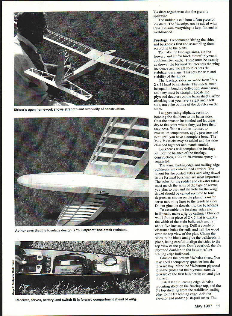
Fuselage
- Kitting and sides
- Kit the sides and bulkheads first, then assemble the fuselage sides.
- Cut forward and aft 1/32" birch aircraft plywood doublers (two each). The forward doubler sets wing incidence; the aft doubler sets stabilizer decalage (trim stability). These must match the plans exactly.
- Make the fuselage sides from 3/32" x 2" x 36" hard balsa sheets. Select sheets equal in bending/deflection, straight and true.
- Locate and trace the plywood doublers on the balsa sides.
- Bonding and assembly
- I suggest aliphatic resin to bond doublers to the balsa sides: coat bonding areas, let dry until just losing tack, then apply heat and pressure with a clothes iron (maximum temperature) until a complete bond is achieved.
- Add 3/32" x 3/16" sticks as required, clamp sides together and match-sand.
- Use 20–30 minute epoxy for critical structural glue-ups.
- Bulkheads, dowels, and servo layout
- Bulkheads complete the fuselage kit. The wing leading-edge, trailing-edge and bulkheads are critical load carriers.
- Layout control-tube and wing-dowel holes in the forward bulkhead. Holes for rudder/elevator tubes must match the servo arm type shown on the plans.
- The hole for the wing dowel should be canted up 3–4 degrees as shown on the plans. Transfer servo-mounting lines to the fuselage sides. Do not glue the wing dowel into the forward bulkhead; the front dowel should be a tight slip-fit for later access.
- Make a jig from a 2" x 6" block exactly the width of the main bulkheads and about five inches long. Drill nail clearance holes, nail the block over the top-view plan, clamp sides to the block and glue bulkheads in place, aligning to the plan.
- Don't overlook the 1/32" plywood doubler for the bottom trailing-edge bulkhead.
- Bottom sheeting, nose and fairing
- Glue the bottom 1/16" balsa sheet; a temporary spreader into the forward bay may be needed. Mark and shape the 1/16" bottom plywood (note plywood extends forward of the first bulkhead); cut and glue in place.
- Install the fin leading-edge 1/8" balsa mounting sheet on the fuselage top and the 1/16" top sheeting from the stabilizer leading edge to the fin leading edge.
- The prototype used Sullivan carbon-fiber push-pull rods—easy to install, friction-free, and temperature-stable.
- Add the nose block and the 1/4" balsa-sheet bottom fairing; ensure full bonding. The top aft 1/16" sheeting can be completed now.
- Laminate the nose hatch from two 1/4" balsa sheets, slightly oversize. Do not shape the underside where it goes over the wing; that area must be fitted after the wing is completed. Lightly tack-glue the hatch in place.
- Fair the nose, top and bottom, to plan shape. Shape and install 1/4" triangular stabilizer mounting strips. The aft fuselage corners need only minimal rounding.
- Fiberglassing the bottom forward fairing is strongly recommended for durability and nose strength.
- Final fuselage details
- Glue the rear wing dowel in place once ready. The front dowel should be a snug slip-fit for service access.
- Install elevator and rudder push-pull tubes, and fix control tubes at bulkheads/top of fuselage with a dab of epoxy.
- Ensure holes and tube alignments match servo arm geometry and control horn locations.
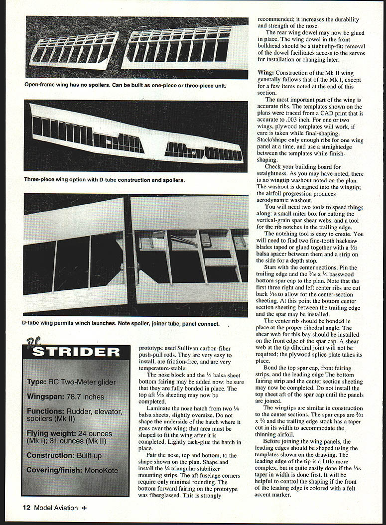
Wing (general)
- Accurate ribs are the most important part of the wing. Templates on the plans were traced from a CAD print accurate to .003". For one or two wings, plywood templates are acceptable if care is taken in final shaping.
- Stack and shape only enough ribs for one wing panel at a time and use a straightedge between templates while finish-shaping.
- Check your building board for straightness. No wingtip washout is shown on the plan—the airfoil progression produces aerodynamic washout built into the plan.
- Tools: a small miter box for cutting vertical-grain spar shear webs and a simple rib-notching tool for trailing-edge notches.
- Notching tool: tape or glue two fine-tooth hacksaw blades together with a 1/32" balsa spacer between them and a side strip as a depth stop.
- Center section
- Start with the center sections. Pin the trailing edge and the 3/16" x 1/4" basswood bottom spar cap to the plan.
- Note: the first three right and left center ribs are cut back 1/16" to allow for center-section sheeting.
- Install the bottom center-section sheeting between the trailing edge and the spar.
- Bond the center rib at the proper dihedral angle. Install the shear web for this bay on the front edge of the spar cap.
- A shear web at the tip dihedral joint is not required; a plywood splice plate takes its place.
- Bond the top spar cap, front fairing strips, and leading edge. Complete the bottom fairing strip and center-section sheeting. Do not install the top sheet aft of the spar cap until panels are joined.
- Tip sections
- Wingtips are similar to center sections. Spar caps are 3/32" x 1/4" and trailing-edge stock is tapered in width to accommodate the thinning airfoil.
- Before joining panels, shape the leading edges using the templates. Tip leading edges require a 1/16" taper in width first; marking the front with a felt marker helps control shaping.
- Joining and finishing
- Join center sections with the plywood joiner. The dihedral angle shown is critical to flight handling—deviations affect handling.
- Complete top sheeting. Apply fiberglass tape on the center section—this area sees the highest stress. Use a touch of CyA to hold the cloth while applying epoxy finishing resin. Attach tips and finish-sand.
Mk II Wing
- Five wing ribs are modified for spoilers as shown on the plans.
- Leading edge is two-piece: a balsa sub-leading edge for bonding the LE sheeting and a basswood cap bonded after sheathing.
- When applying sheeting with aliphatic resin, dampen the bonding area with water to slow setting and allow proper bonding.
- Install bottom sheet first and weight the wing on a flat surface until dry for each sheet applied.
- Caution: trim sheeting stock so grain orientation matches the plan. If sheet grain aligns with the spar incorrectly, stresses may pull in a warp that is difficult or impossible to correct. An overly stiff warped Mk II wing may be unfixable.
Three-Piece Wing Option
- Alignment is crucial. Stack-sand the four 1/8" hard balsa ribs together while still pinned, and drill the 1/32" and #64 holes as located on the templates.
- Include the 1/32" plywood plate fore and aft on the spar cap to box in the tube and wire.
STRIDER
Specifications
- Type: RC Two-Meter glider
- Wingspan: 78.7 inches
- Functions: Rudder, elevator, spoilers (Mk II)
- Flying weight: 24 oz (Mk I); 31 oz (Mk II)
- Construction: Built-up
- Covering/finish: MonoKote recommended
COVERING / ASSEMBLY
- Finish-sand all assemblies and inspect against the plans. Vacuum and wipe away all sanding dust with a tack cloth before covering.
- Balance the wing about the centerline before covering and add weight as required.
- Covering: MonoKote is strongly suggested for the Mk I wing for torsional rigidity; less-rigid coverings may allow wing flutter during launch or at high speed.
- Hinges: Do not use leaf-type hinges—the slots weaken structure and reduce control efficiency. Use covering-type hinges or Scotch™ plastic tape as noted above.
- When installing tail surfaces, remove covering from bonding areas and ensure secure bonds. Install wing-saddle tape.
- Radio and control linkage:
- Install radio components per the radio instructions.
- Use short nylon clevises at the servo end for push-pull rods. Control tube should not protrude more than 1/8" forward of the front bulkhead.
- Epoxy the control tubes at each bulkhead and at the top of the fuselage for security.
- Set clevis positions so full servo rotation yields approximately ±30° elevator and ±45° rudder with dual rate off.
- First-time fliers: set rudder dual rate to ±30° and elevator to ±15°. As experience grows, increase rates for better performance.
FLYING
- Preflight inspection is critical. Inspect the wing for warps: the flat underside of each panel should lay flat on a level surface. Warps can make the model difficult or impossible to control on launch or in flight.
- Attach the wing with four top-quality #64 rubber bands for hi-start launches (use five for winch launches).
- Nose hatch: held by a retainer (light, stiff, ~1/32" thick) fitted under the wing rubber bands; slide retainer tangs over the aft edge of the hatch.
- Controls: stand behind the model and verify control directions (right stick -> right rudder, stick away -> elevator down, stick toward -> elevator up).
- Center of Gravity (CG): mark the CG on the bottom of the wing with a felt-tip pen. Add lead to the nose until the model balances at the marked CG. If it balances aft of the CG, elevator authority is reduced.
- Initial flights: perform some hand launches in a soft area to check trim. For the first hi-start or winch launches, have an experienced pilot or instructor make the first few flights.
- In sink or downwind conditions: a few clicks of down trim and a short push of stick forward to gain airspeed, then back to neutral, will let the Strider accelerate and penetrate.
- Ballast: after you are comfortable flying the Strider, increase wing loading with ballast for windy days or slope flying.
- Aerobatics: for inverted flight, full elevator travel is required as inverted attitude demands full elevator authority.
Try the Strider—you'll like it. Twenty members of my club, from novice to expert, have thoroughly enjoyed it.
My goal for 1997 was to use the Strider to complete League of Silent Flight Levels I, II, and III.
Dick Birdwell 2481 Skylark Dr. #7 San Jose, CA 95125
Transcribed from original scans by AI. Minor OCR errors may remain.

