
RC THISTLE
Are you tired of big, high-cost, high-tech projects? Get back to basics and have some fun with the RC Thistle!
Each category of flying models has advocates for making models that are as small as possible—maybe because modeling is a miniaturization of full-scale aviation. Radio control can definitely be included; several indoor models have flown successfully with very light radio equipment. Over the years, very small commercially available radio gear has been developed.
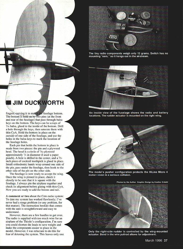
The original (free flight) Thistle was published in the February 1995 Model Aviation; that article gives the particulars of constructing an all-balsa light aircraft. Small aircraft are often covered with tissue, but by using light balsa the Thistle has a better chance of surviving entanglements with bushes and other hazards. Also, because the motor is mounted high in a pusher configuration, it is protected—even in a serious collision. Most mishaps can be readily repaired with a little cyanoacrylate (CyA) glue.
CONSTRUCTION
The RC Thistle follows the same construction methods as the free-flight version. Materials must be chosen carefully to ensure the lightest possible airframe.
- Wing stock: select a light, straight piece for the 1/2" x 4" x 36" balsa wing. Don't grab just any piece of 1/2" for the wing and tail—it's too easy to end up with a heavier-than-necessary piece in the tail.
- Tailbooms: medium-grade 3/32" balsa; even hard, close-grained balsa works nicely.
- Fuselage sides: light-to-medium 1/16" balsa. Medium grade is preferred for the handling and hole punching involved.
Use the full-size templates to lay out components. Refer to the original Thistle article for complete construction details; the following highlights the key steps.
Wing
- When forming the wing, wet the top side, then immediately apply thin dope to the bottom. When everything is dry, the undercamber should be close to that shown on the fuselage template.
- While drying, you can "work" the wing to induce or reduce curvature; be sure it does not twist. A hair dryer on medium heat will speed drying.
- After the wing has formed its permanent undercamber, cut it into three pieces—one center section and two outer panels. Use the dotted line on the wing template to make a curved cut on the outer panels. When mated with the center section, the curved cut forms a neat joint.
- Prop the outer panels up 1/4" and apply thin CyA to the joint. Set the completed wing aside until the fuselage is ready.
Fuselage
- Glue the fuselage sides together along the top edge, then separate them when the triangular former is inserted between them. The former location is indicated on the fuselage template.
- Glue the front and rear points of the fuselage sides together. The area of the rudder where the motor will be installed should be glued so it becomes a laminate of the two sides.
- Bottom: 1/32" balsa. No template is supplied—hold a piece of balsa against the fuselage bottom and trace it to match your fuselage shape. Form the bottom by pulling and curving it with your fingers to match the fuselage.
- Bottom attachment: the bottom is held by two pins (front and rear) that pass through balsa keys on the inside of the bottom. Make keys from 1/16" scrap balsa, glue them inside the bottom, drill holes through them, then saturate with thin CyA. Hold the bottom in place on the outside of one fuselage side and use the holes in the keys to mark fuselage hole locations.
Pin construction
- Each pin is two pieces: the pin and a plywood head. The head is a circle of 1/64" plywood approx. 1/4" in diameter (a paper punch works well). Drill a center hole and glue a 1/8" piece of cocktail toothpick into it.
- Small orthodontic bands wrap around one side of the pin, pass under the fuselage, then hook to the other side of the pin to hold the bottom on.
Assembly
- The fuselage is now ready to accept the wing. Once the wing is pinned in place, check closely to be sure it is square with the fuselage. Pin the airplane together and verify alignment before gluing with thin CyA.
- Now add the booms and tail.
A comment or two about the radio system
To date my radio system has worked flawlessly; I've never had a range problem. The instruction booklet is straightforward.
There are a few practical hurdles:
- The radio is supplied with excess wire for an airplane the size of the Thistle. You could shorten leads to save weight and simplify component placement, but some builders avoid cutting for fear of detuning the system. The alternative is to stuff the excess wire and components into the fuselage—functional though not elegant.
- The tiny switch has no mounting "ears," so it hangs in the airstream. This is a functional solution but unsightly. Another simple approach is to let the switch hang out, as it works.
Mounting components
- I use 1/16" sticky-back foam tape to hold radio components. Wrap a piece of plastic wrap around your finger, smear thin CyA on the inside of the fuselage, and let it dry. The cured CyA forms a base where the foam tape will adhere.
- Insulate a very small piece of tape on each component until after initial flights. This allows you to move batteries to obtain an acceptable center of gravity (CG).
Controls
- The movable rudder is shown on the rudder template; the throw is indicated on the horizontal tail template. Both rudder size and throw can be adjusted to suit your needs.
- The rudder pullrod has a bend in it—place this bend where it's easy to reach with a hemostat or small needle-nose pliers so minor adjustments can be made. The pullwire ends are bent into a Z.
- The control horn is made from 1/64" plywood and is interlocked at 90° to the rudder with thin CyA.
- Rudder hinges must be very limber—any drag will prevent the actuator from functioning. I used two pieces of 3M frosted tape, each 1/4" square. Apply them with finger pressure and then heat with a hair dryer to set the adhesive.
- Some experimentation is required to get the system free enough so the actuator moves the rudder snappily.
FLYING
- Success with the RC Thistle starts with test flying. Do test flights with the motor nearly run down.
- For first test flights, fly the Thistle as a free flight model. If the CG is in the proper location (as indicated on the fuselage template), power and glide patterns should be close to correct.
- Adjust rudder and elevator trim to achieve the desired climb, glide, and circle. There should be room in the fuselage for small changes in radio placement to adjust CG.
- Once you have a nice right circle about 20–30 feet across where the Thistle climbs gently and glides without bad tendencies, you can begin to use the radio.
- On the first radio-controlled flight, let the model attain some altitude (about 20 feet) before using the radio.
TEMPLATES / NOTES
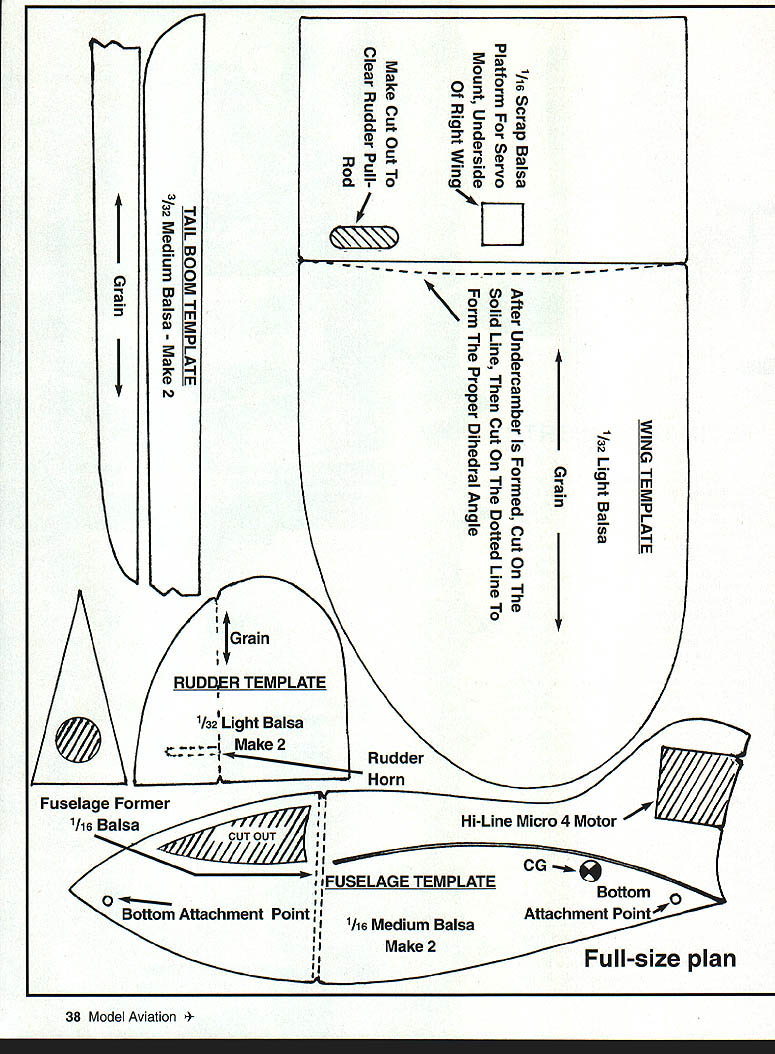
- Tail Boom Template: 3/32" medium balsa — make 2 (grain as indicated).
- Rudder Template: 1/32" light balsa — make 2 (grain as indicated). Include cutout to clear rudder pull-rod and rudder horn.
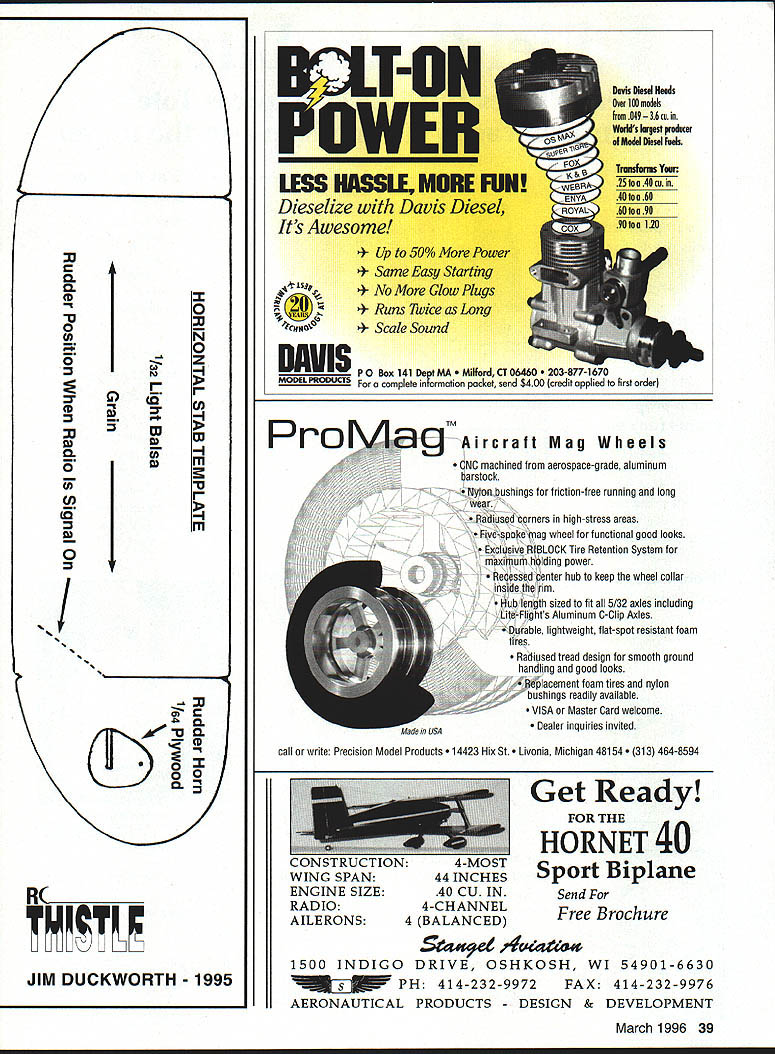
- Rudder Horn: 1/64" plywood.
- Rudder pull-rod: ends bent into a Z.
- Servo mount platform: 1/16" scrap balsa — mount forward side inside of right wing.
- Wing Template: 1/32" light balsa. After undercamber is formed, cut on the solid line, then cut on the dotted line to form the proper dihedral angle.
- Fuselage Former: 1/16" balsa.
- Fuselage Template: 1/16" medium balsa — make 2. Mark bottom attachment points and CG.
- Horizontal Stabilizer Template: 1/32" light balsa. Rudder position when radio is signal-on indicated.
SPECIFICATIONS
- Type: RC Sport Electric
- Wingspan: 16 inches
- Motor: Hi-Line Micro 4
- Function(s): Rudder only
- Construction: Balsa sheet
RC THISTLE Jim Duckworth — 1995
Transcribed from original scans by AI. Minor OCR errors may remain.

