
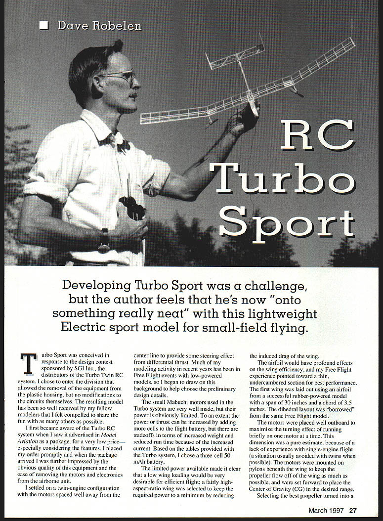
RC Turbo Sport
Dave Robelen
Developing Turbo Sport was a challenge, but I feel I'm now onto something really neat with this lightweight electric sport model for small-field flying.
Turbo Sport was conceived in response to a design contest sponsored by SGI Inc., the distributors of the Turbo Twin RC system. I entered the division that allowed removal of the motors and electronics from the plastic airborne housing, but prohibited circuit modifications. The resulting model has been so well received by fellow modelers that I felt compelled to share the fun.
I first became aware of the Turbo RC system when I saw it advertised in Model Aviation as a package for a very low price—especially considering the features. When the package arrived I was impressed by the obvious quality of the small Mabuchi motors and the ease of removing the motors and electronics from the airborne unit.
I settled on a twin-engine configuration with the motors spaced well outboard to provide some steering effect from differential thrust. Much of my recent modeling has been in free-flight events with low-powered models, and I drew on that background when choosing preliminary design details.
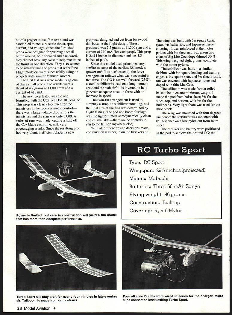
The small Mabuchi motors are well made but their power is limited. Thrust can be increased by adding cells to the flight battery, but that adds weight and increases current draw. Based on the tables provided with the Turbo system, I chose a three-cell, 50 mAh battery.
The limited power made a low wing loading desirable for efficient flight. I chose a fairly high-aspect-ratio wing to minimize induced drag. Airfoil selection was important: my free-flight experience favored a thin undercambered section. The first wing used an airfoil from a successful rubber-powered model with a span of 30 inches and a chord of 3.5 inches. The dihedral layout was borrowed from that same free-flight design.
The motors were mounted on pylons beneath the wing and set well outboard to maximize turning effect when running briefly on one motor. They were set forward to help place the center of gravity (CG) in the desired range.
Propeller testing
Selecting the best propeller became a project. I built a test stand to measure static thrust, rpm, current, and voltage. The supplied props were designed to push a small blimp both forward and backward and had little twist to maximize thrust in one direction. I also tried smaller props that other free-flight modelers were using with similar Mabuchi motors.
The first test runs with a small prop produced about 47 grams of thrust at 11,000 rpm while drawing 410 mA. The supplied Cox Tee Dee .010 engine prop required too much current and produced a large voltage drop across the motor-control transistors; rpm fell to about 5,000. I made a series of runs cutting a little off the Cox blades; results were encouraging but the blades remained blunt and inefficient. I then designed and carved a new prop from basswood for flight. That prop produced about 75 grams of thrust at 11,500 rpm while drawing 360 mA. The flight prop is about 2-1/4 inches in diameter with a 1-3/8-inch pitch.
Controls and stability
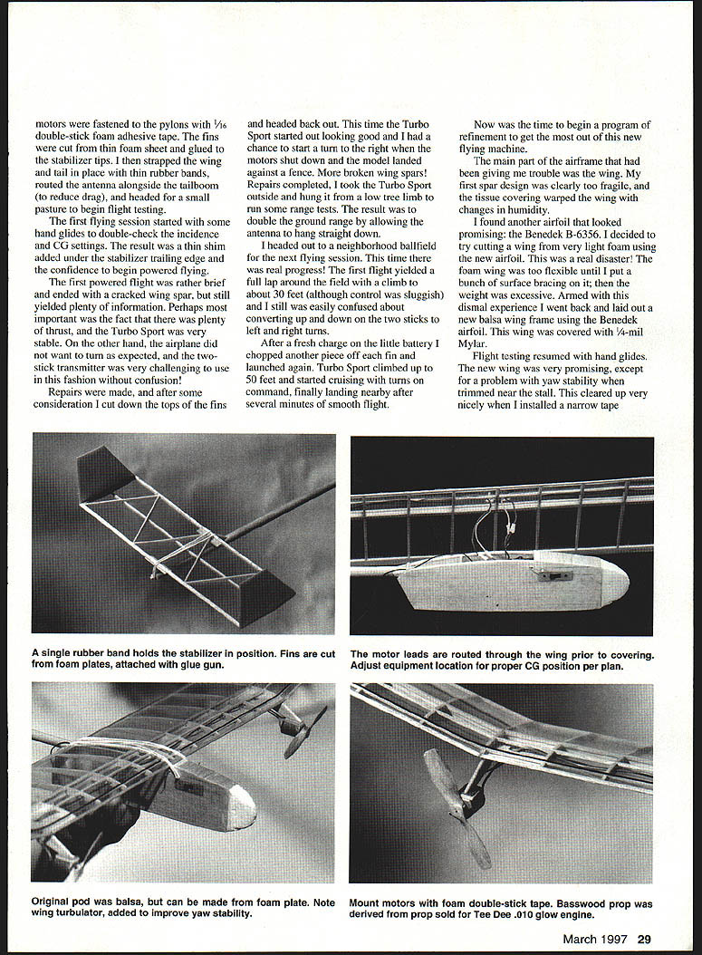
The model uses simple on/off power control similar to early RC designs. The CG was set well forward (about 25% chord); a small stabilizer with a long moment arm was used. The stabilizer airfoil was inverted to help generate adequate nose-up force with increased speed. A twin-fin arrangement simplified strap-on stabilizer mounting. Final fin size was determined by flight testing.
A pod-and-boom fuselage was the lightest and most aerodynamically clean choice since there were no aft-running controls. With these design decisions made, construction began.
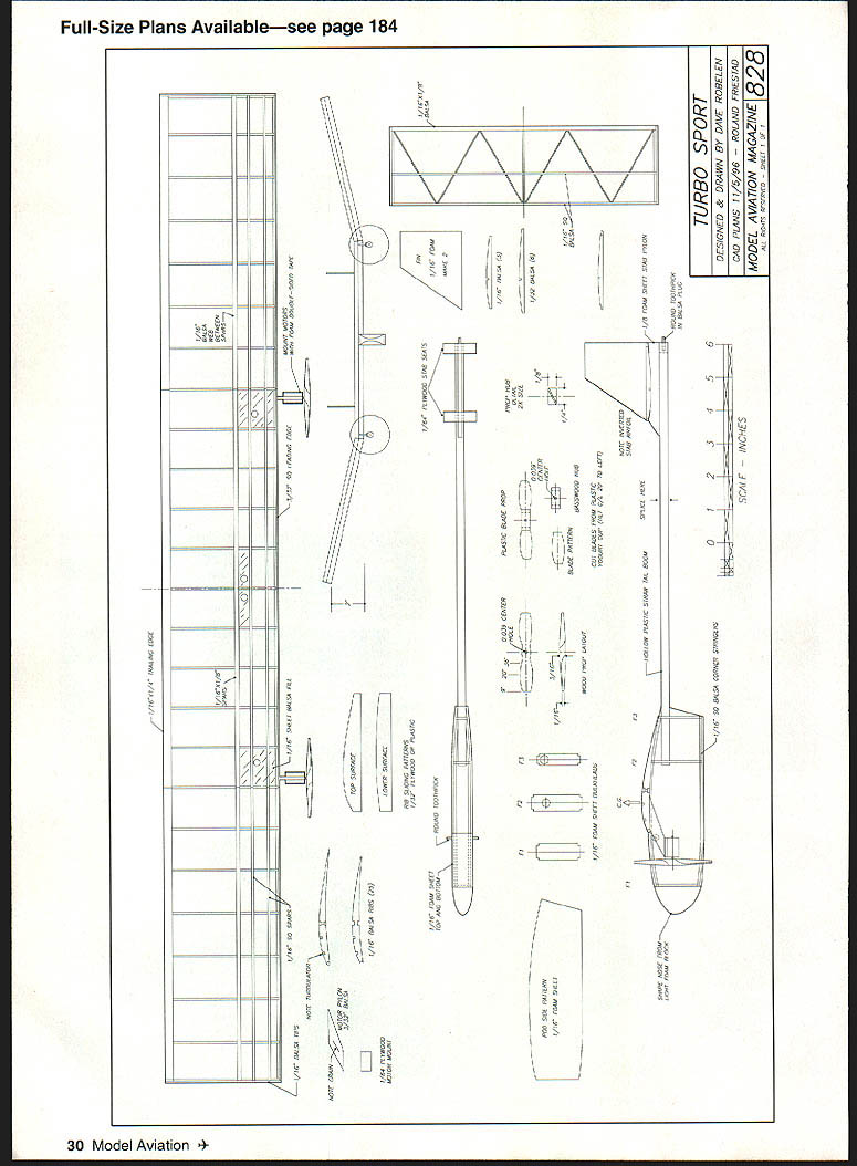
CONSTRUCTION
I assume you can comfortably build a lightweight stick-and-tissue model; if not, try a One Nite 28 kit to learn the techniques. The construction here is not hard, but it may be different from some past projects.
When I refer to light or medium wood I mean the type Sig markets as Contest Balsa. A 1/16 x 3 x 36 sheet of light wood weighs about 12 grams; medium weighs about 18–20 grams. Thinner wood such as 1/32 weighs proportionately less.
My preferred adhesive is a cyanoacrylate (CA) glue called Quick-Tite.
Stabilizer
- Cut the trailing edge, leading edge, and spar from medium wood; ribs from light stock.
- Protect the plan with waxed paper and pin the leading and trailing edges in place.
- Glue the ribs in place, using glue sparingly.
- Glue the spar in place, lift the assembly from the board, sand smooth, and set aside.
Wing
- Make rib-slicing templates from thin plywood or plastic using the plan patterns. Make sure they are smooth.
- Cut several pieces of light 1/8-inch balsa sheet to the length of the wing rib. Use the templates to slice the top- and bottom-surface curves to form rib blanks; repeat until you have a stack of ribs.
- Use a small square needle file to cut spar notches cleanly.
- Cut clearance holes in the ribs where motor leads will pass through.
- Prepare a 1/16 x 3/4 strip of firm balsa for the trailing edge and clamp on the plan, using thin shims to maintain the airfoil.
- Sand and shape a 3/32 square strip for the leading edge and clamp in place.
- Glue all ribs in place, tilting the ones at the dihedral joint slightly inward.
- When dry, unpin the tip sections, prop them to the dihedral angle, glue leading and trailing edges securely, and add top spars.
- When dry, lift the wing, glue spar webs and bottom spars, add bottom-surface filler pieces and wingtips, and sand smooth.
Covering: You may substitute tissue for the 1/4-mil Mylar. The weight difference is small, but Mylar is much more stable with changes in humidity.
If using Mylar, paint an adhesive on frame areas where you want it to stick (I recommend Balsarite Plastic Film Formula). A MonoKote trim-seal iron is a handy covering tool. Do not shrink the covering until it is sealed down tightly.
Fins
- Cut from 1/32-inch balsa and attach with CA.
- Alternatively, use thin foam sheet (from foam plates) attached with a small hot-glue gun for superior moisture resistance and good strength. Work quickly and spread glue thin.
Fuselage
- The tailboom was originally a rolled balsa tube, but commercial plastic straws (such as McDonald's or Burger King) plug together and make a superior, lightweight tailboom — I strongly recommend them.
- The pod can be balsa sheet or foam from plates. Reinforce the stabilizer mount area with 1/64 plywood and a dab of epoxy to hold a small round toothpick mount.
- Start by gluing the tailboom to the rear bulkheads, then add and glue side plates, front bulkhead, and top and bottom sheets.
- Trim a nose piece from a very light foam block. I cut the stabilizer mount from a 1/8-inch foam meat tray and glued it on with hot glue. Stabilizer braces are cut from 1/4-inch plywood—watch alignment (no stab tilt).
- Glue a small plug of wood in the end of the boom and glue a piece of toothpick into that to form the tailplug.
Assembly
- Mount the motors with double-stick picture-mounting foam tape.
- Assemble receiver, switch, and battery as a package outside the fuselage. I use a short length of wire from each side of the battery through the fuselage sides as charging connections.
- Slip the gear into the pod and hook up the wing. Leave about four inches of slack in the motor wires and directly connect the wing wires to the receiver leads. Be sure left and right are correctly sorted!
- Use thin office rubber bands to strap the wing and stabilizer in place: one band for the stab, two for the wing.
- Check balance and move components inside the pod until the CG matches the plan.
Props
- Carve wooden props from basswood per the plan, or use plastic blades. Wooden props are slightly more efficient; plastic works fine.
- Work slowly and carefully to make smooth-running, well-balanced props.
- After mounting props, attach the motor leads and power up the radio. Check motor rotation: if the motors pull forward when you push the stick up, that’s correct; if not, reverse the wires.
- If you have a tachometer, check rpm with a full charge. You should see at least 11,000 rpm; substantially less means props may have too much pitch. The tip should measure about 9 degrees—check and correct as needed.
FLYING
Start with hand glides over a soft surface. Use thin shims under the stabilizer until the glide is nearly stalling, and trim the tail until the glide is straight. Expect a toss glide of about 60–75 feet.
For the first powered flights, a helper is ideal. If solo, hold both transmitter sticks forward with a thumb while gripping the transmitter without touching the antenna. Launch as you did for hand glides and watch closely:
- Does it climb smoothly?
- Stall slightly?
- Turn or go straight?
Plan on quick shutdowns to review and make adjustments. When Turbo Sport climbs in a smooth circle of 75–100 feet, begin learning differential-thrust turns.
Under power, the airplane turns toward the stick that is pulled back to center (reducing power on that side); during gliding flight the plane turns away from the stick pushed forward. Turbo Sport is responsive—small power bumps start a turn. There is no need for reverse thrust for extreme measures.
I started flight testing with hand glides to double-check incidence and CG. A small shim under the stabilizer trailing edge and a few adjustments produced confidence to begin powered flying.
The first powered flight ended with a cracked wing spar but confirmed there was plenty of thrust and good stability. Early flights revealed sluggish turning and some confusion using a two-stick transmitter for differential thrust. Repairs and trimming of the fins improved control. Hanging the model from a low tree limb during range checks doubled the ground range by letting the antenna hang straight down.
Progress followed: first a full lap around a neighborhood ballfield with a climb to about 30 feet, then later flights to 50 feet cruising with turns on command and several minutes of smooth flight. Further refinement focused on strengthening the wing and improving covering stability.
Wing refinement
The first spar design was too fragile and the tissue covering warped with humidity changes. I tried a foam wing cut to the Benedek B-6356 airfoil, but it was too flexible until heavily braced, which made it too heavy. I then built a new balsa wing frame using the Benedek airfoil and covered it with 1/4-mil Mylar.
Flight testing with the new wing was promising, although I encountered yaw instability near the stall. Adding a narrow tape strip along the top of the center section gave a little keel effect and cured the problem. I also increased washout near the tips to keep the tips from stalling early.
I experimented with trimming the tail for a very large steady-power circle; this trim helped a lot. I could watch Turbo Sport climb hands-off and practice turns while gliding at a safe height. I was able to keep the model inside a 120-foot-square field, handle a moderate breeze, and keep the Turbo Sport aloft for almost four minutes in late-evening air. Using parking-lot lights made night flying practical, and small thermals often kept the model aloft five to six minutes.
Charging
I made a simple field charger by wiring four alkaline D cells in series, tightly wrapped with strapping tape. Alternate cell placement allows jumper wires to form a six-volt pack. Add a two-foot cable with micro clips to attach to the model’s charging wires.
I monitor charge with a pocket digital meter. Clip the charger to the model charging wires and watch voltage; when it stops increasing, the battery is fully charged. In practice, a full charge takes less than two minutes.
I have enjoyed this project and hope others can share in the fun. Please write and share your comments and experiences.
Dave Robelen Rt. #4 Box 369 Farmville, VA 23901
Sources
- Balsa, tissue, Balsarite, music wire, tools: Sig Mfg. Co., 401-7 S. Front St., Montezuma, IA 50171
- 1/4-mil Mylar: Ed Turner, 3544 Granada Dr., Fort Worth, TX 76118
- Foam plates, CA glue, hot-glue gun: Wal-Mart
- Micro clips, wire, meters, soldering equipment: Radio Shack
Transcribed from original scans by AI. Minor OCR errors may remain.

