
Re-Volt-er
Clarence Haught
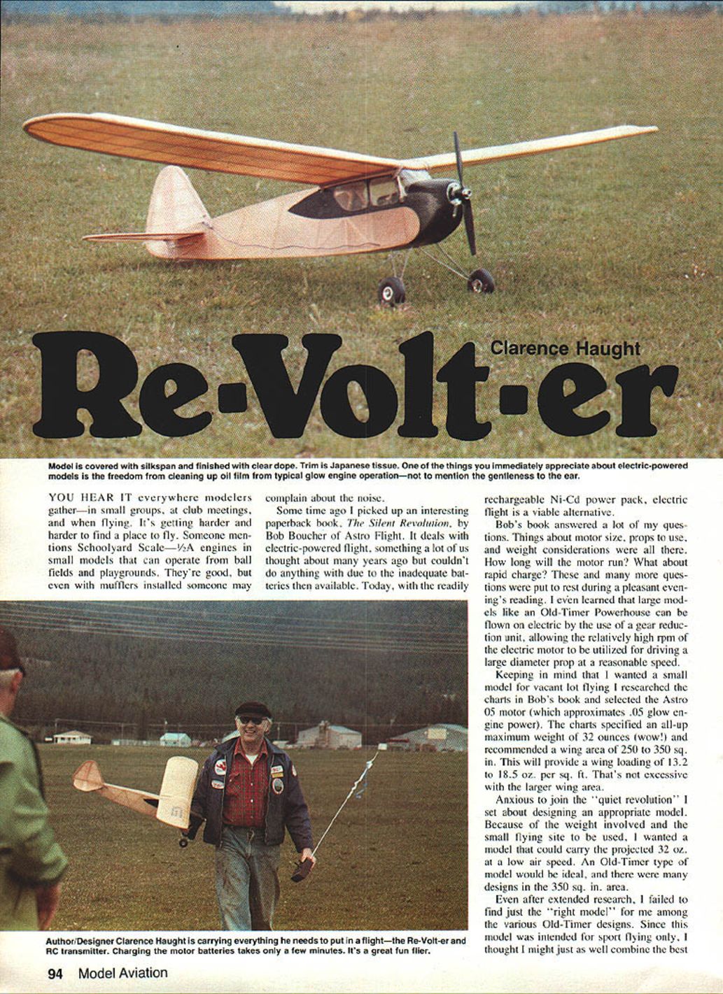
You hear it everywhere modelers gather—in small groups, at club meetings, and when flying. It's getting harder and harder to find a place to fly. Someone mentions Schoolyard Scale—1/2A engines in small models that can operate from ball fields and playgrounds. They're good, but even with mufflers installed someone may complain about the noise.
Some time ago I picked up an interesting paperback, The Silent Revolution, by Bob Boucher of Astro Flight. It deals with electric-powered flight, something a lot of us thought about many years ago but couldn't do anything with due to the inadequate batteries then available. Today, with the readily rechargeable Ni-Cd power pack, electric flight is a viable alternative.
Bob's book answered a lot of my questions. Things about motor size, props to use, and weight considerations were all there. How long will the motor run? What about rapid charge? These and many more questions were put to rest during a pleasant evening's reading. I even learned that large models like an Old-Timer Powerhouse can be flown on electric by the use of a gear reduction unit, allowing the relatively high rpm of the electric motor to be utilized for driving a large-diameter prop at a reasonable speed.
Keeping in mind that I wanted a small model for vacant-lot flying, I researched the charts in Bob's book and selected the Astro .05 motor (which approximates .05 glow engine power). The charts specified an all-up maximum weight of 32 ounces and recommended a wing area of 250 to 350 sq. in. This will provide a wing loading of 13.2 to 18.5 oz. per sq. ft.—not excessive with the larger wing area.
Anxious to join the "quiet revolution," I set about designing an appropriate model. Because of the weight involved and the small flying site to be used, I wanted a model that could carry the projected 32 oz. at a low airspeed. An Old-Timer type of model would be ideal, and there were many designs in the 350 sq. in. area.
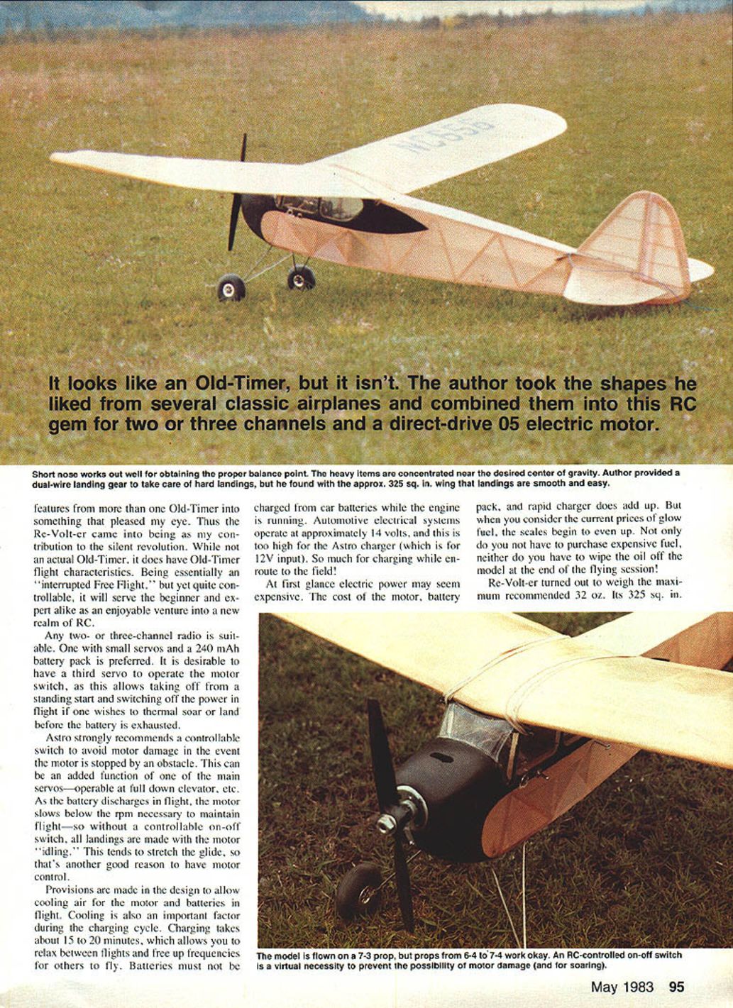
Even after extended research, I failed to find just the "right model" for me among the various Old-Timer designs. Since this model was intended for sport flying only, I thought I might just as well combine the best features from more than one Old-Timer into something that pleased my eye. Thus the Re-Volt-er came into being as my contribution to the silent revolution. While not an actual Old-Timer, it does have Old-Timer flight characteristics. Being essentially an "interrupted Free Flight," yet quite controllable, it will serve the beginner and expert alike as an enjoyable venture into a new realm of RC.
Radio, Controls, and Motor Management
Any two- or three-channel radio is suitable. One with small servos and a 240 mAh battery pack is preferred. It is desirable to have a third servo to operate the motor switch, as this allows taking off from a standing start and switching off the power in flight if one wishes to thermal soar or land before the battery is exhausted.
Astro strongly recommends a controllable switch to avoid motor damage in the event the motor is stopped by an obstacle. This can be an added function of one of the main servos—operable at full down elevator, etc. As the battery discharges in flight, the motor slows below the rpm necessary to maintain flight—so without a controllable on-off switch, all landings are made with the motor idling. This tends to stretch the glide, so that's another good reason to have motor control.
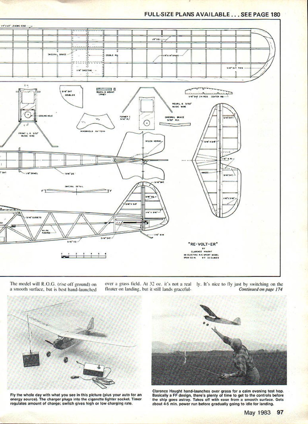
Provisions are made in the design to allow cooling air for the motor and batteries in flight. Cooling is also an important factor during the charging cycle. Charging takes about 15 to 20 minutes, which allows you to relax between flights and free up frequencies for others to fly. Batteries must not be charged from car batteries while the engine is running. Automotive electrical systems operate at approximately 14 volts, and this is too high for the Astro charger (which is for 12V input). So much for charging while en route to the field!
At first glance electric power may seem expensive. The cost of the motor, battery pack, and rapid charger does add up. But when you consider the current prices of glow fuel, the scales begin to even up. Not only do you not have to purchase expensive fuel, neither do you have to wipe the oil off the model at the end of the flying session!
Re-Volt-er Characteristics and Specifications
Re-Volt-er turned out to weigh the maximum recommended 32 oz. Its 325 sq. in. wing area gives a wing loading of 14.2 oz. per sq. ft. The model is normally flown on a 7-3 prop (7 in. diameter, 3 in. pitch — an FAI size), but props from 6-4 to 7-4 work okay. Flight speed is slow and realistic, and the model is quite maneuverable.
- All-up weight: 32 oz.
- Wing area: 325 sq. in.
- Wing loading: 14.2 oz. per sq. ft.
- Typical prop: 7 in. x 3 in. (range 6-4 to 7-4)
- Motor: Astro .05
- Recommended radio: 2- or 3-channel with small servos and 240 mAh pack
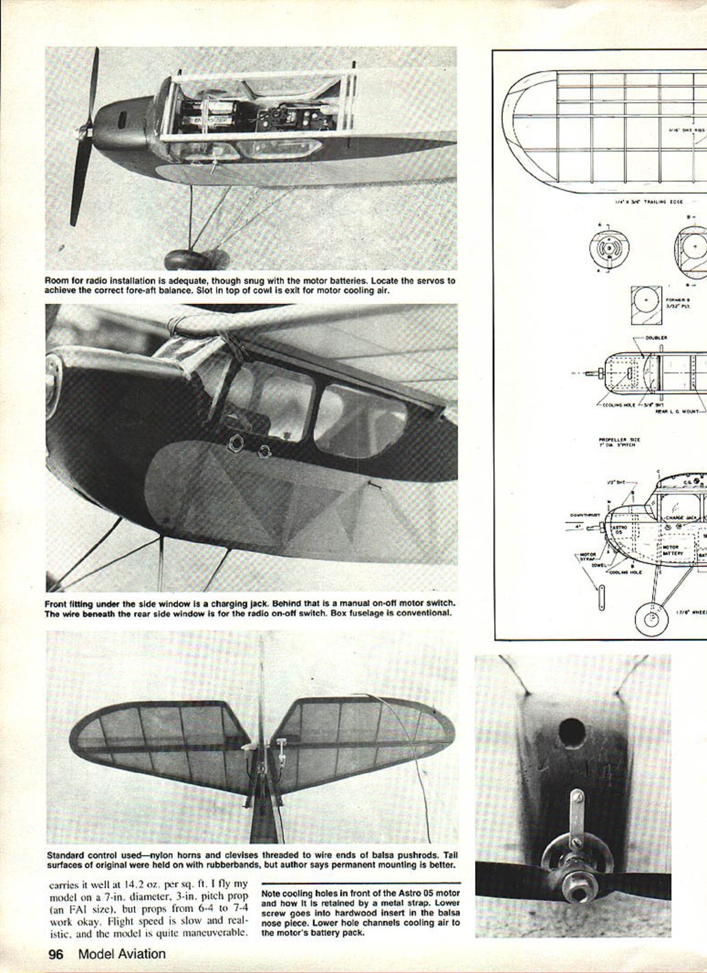
The motor is retained by a metal strap; a lower screw goes into a hardwood insert in the balsa nose piece. Cooling holes in front of the Astro .05 motor and slots in the top of the cowl provide exit for motor cooling air. A lower hole channels cooling air to the motor and battery pack.
The model will R.O.G. (rise off ground) on a smooth surface, but is best hand-launched over a grass field. At 32 oz. it's not a real floater on landing, but it still lands gracefully. It's nice to fly just by switching on the radio and power—no fuss, no muss!
Construction
Wing
I prefer to begin construction here. All ribs are the same except the three center ribs which are trimmed 1/16 in. on the top and bottom to allow for center section sheeting. I suggest making two card-stock rib templates and stacking the 1/16-in. sheet rib stock between the templates; secure with pins, and carve and sand all ribs to shape at once. Cut spar notches with a razor saw while the ribs are still pinned together. Cut wing tip pieces from 3/16-in. sheet, and glue them together. Cut notches in the 1/4 x 3/4-in. trailing edge pieces for ribs.
Protect the plan with kitchen wrap before pinning down the leading and trailing edges. Add wing tips. Locate the lower spars with the aid of a couple of ribs to ensure proper spacing. Glue center bottom sheeting in place. Install all ribs except the center one.
When glue has dried, remove the wing from the plan, and sand butt ends for the proper dihedral angle. Block up each tip 3 in., and join the wing panels together. Add the dihedral braces as indicated on the plan. Trim the center rib to fit, and glue it in place. When dry, add the top spars and the top center section sheeting. Sand the wing structure to its final shape.
Stabilizer, Elevators, Rudder, and Fin
The tail surfaces are simply glued together from the specified sizes of strip wood and sheet for the tips. Sand to shape, and join the elevators with 1/16-in. music wire. Temporary hinges should be installed for trial fitting; do not glue permanently until final assembly.
Fuselage
Begin by building two identical sides. I suggest building the first side by pinning the parts in such a manner that a sheet of kitchen wrap can be pulled down over the pins to allow the second side to be built right over the first — the kitchen wrap preventing them from sticking together. When dry, remove from the building board, and add sheet balsa nose doublers (making a right and left side).
Cut out plywood formers, and install the front landing gear legs to the appropriate former. The gear may be retained by J-bolts or by binding with soft wire and epoxying the wraps.
Set the fuselage sides upside down on the workbench so they are resting on the wing platform. Join the fuselage sides using the plywood formers and the bottom 3/16-in. sheeting to ensure alignment. A little 5-min. epoxy or cyanoacrylate glue will speed up the process. When dry, pull the rear fuselage sides together, and join them at the rudder post. Add all the other cross braces and the rear landing gear mount.
Cut out the nose block with motor mount hole, and fit the block to the fuselage and motor to provide four degrees of downthrust. Install the top and bottom nose blocks, and sand them to shape. Cut cooling holes in the top and bottom, and install the hardwood dowel motor strap anchor.
Install the window and wing dowel gussets. Fit the wing mount dowels, but don't install them until the model is covered. Add the upper windshield block, fitting it to the wing dihedral angle.
Give the fuselage a final sanding. Install the rear landing gear wire. Glue the wire into the grooved block with epoxy, and reinforce it with a bit of cloth. Bind and solder the landing gear wires at the axle junction. Shape and install the tail skid.
Install the motor, battery pack, charging jack, and switch. The battery pack must lay down to allow cooling air to pass through the hole in the cabin former and through the open center of the battery pack.
Install the radio gear, control horns, and pushrods. I used 1/4-in. sq. balsa pushrods with wire ends as shown on the plans. This system is lightweight and is not affected by temperature changes.
Front fitting under the side window is a charging jack. Behind that is a manual on-off motor switch. The wire beneath the rear side window is for the radio on-off switch. The box fuselage is conventional. Standard control used—nylon horns and clevises threaded to wire ends of balsa pushrods. Tail surfaces of the original were held on with rubber bands, but permanent mounting is better.
Covering and Finishing
Disassemble the model, and remove all equipment in preparation for covering. Use your favorite covering material, keeping in mind that weight is an important factor. I prefer traditional dope-and-tissue finishes. One must use very little pigmented dope, as it adds weight fast.
I covered mine with dyed silkspan. The procedure is simple. The basic structure was given two coats of clear dope where the silkspan was to be adhered, with a light sanding between coats. Prepare dye by dissolving in a pan of warm water. I used Rit brand cloth dye. Cut G/M silkspan to size, and immerse it in the dye solution. Agitate until the silkspan has the desired depth of color. Remove from the dye, and blot the wet silkspan between layers of newspaper.
Lay the still-moist silkspan on the structure, and smooth out the wrinkles. Lift edges, and apply clear dope to stick the silkspan down. Trim with a razor blade, and allow it to dry. Apply two coats of clear dope, and sand very lightly with 400 or 600-grit paper.
Cut desired trim, numbers, stripes, etc., from colored Japanese tissue. Apply with dope thinned and brushed through the trim tissue. Apply three more coats of clear dope for a durable lightweight finish.
Final Assembly and Flight
Fit the windows, windshield, and wing mounting dowels. Glue the tail surfaces permanently in place. Mount wheels. Install motor, batteries, radio gear, and check for proper operation.
Put on the wing with rubber bands, and check the model for alignment. Support the model at the indicated center of gravity. If it does not balance properly, shift equipment or add ballast if necessary.
Pick a nice calm evening and join the "quiet revolution." You'll find the Re-Volt-er's flight characteristics to be slow and gentle. If you get into trouble, the model will recover on its own—given enough altitude—if you release the control sticks. It even makes acceptable landings unassisted if there is adequate room.
Run silent, run high!
Transcribed from original scans by AI. Minor OCR errors may remain.

