
Rearwin
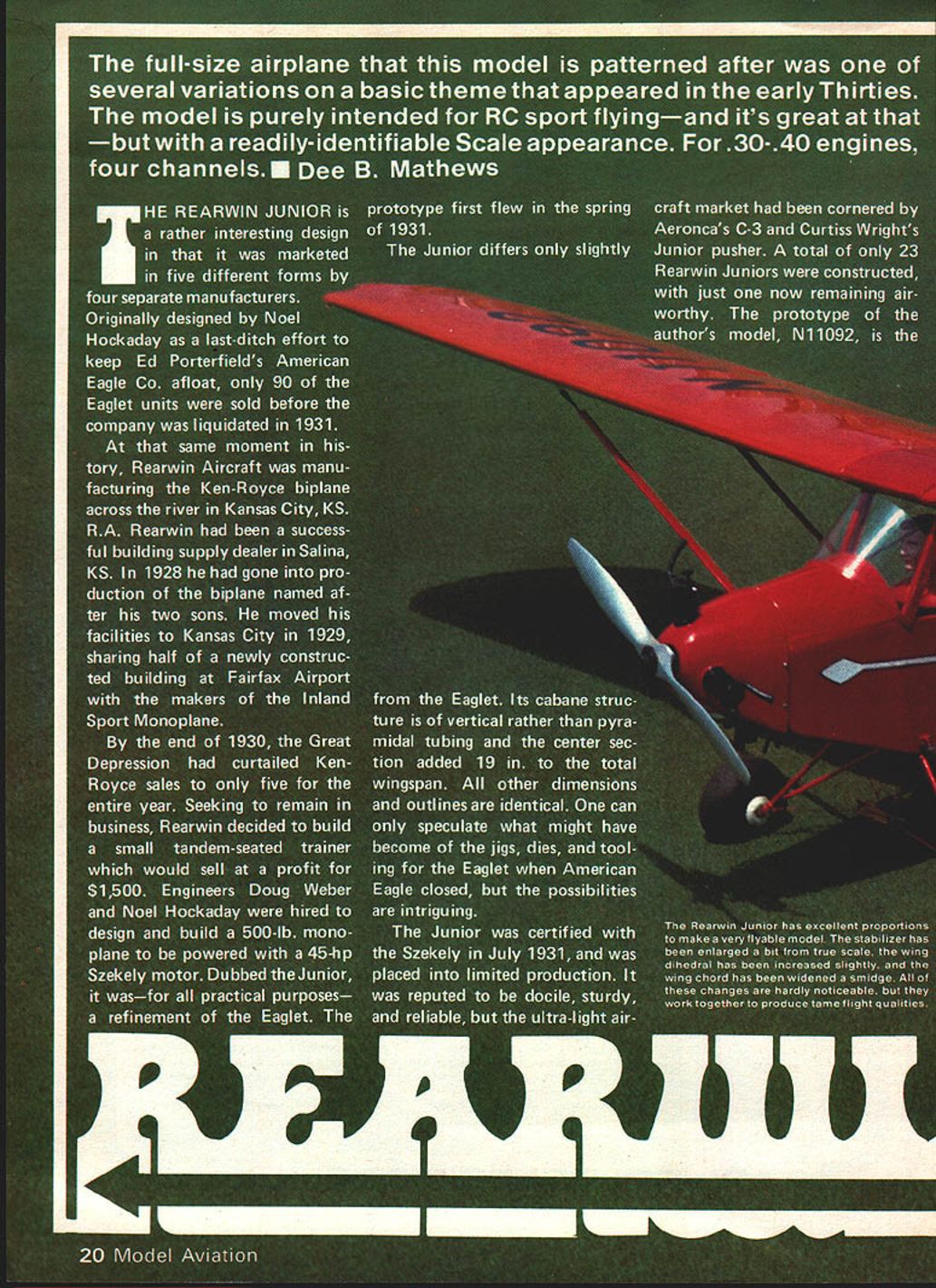
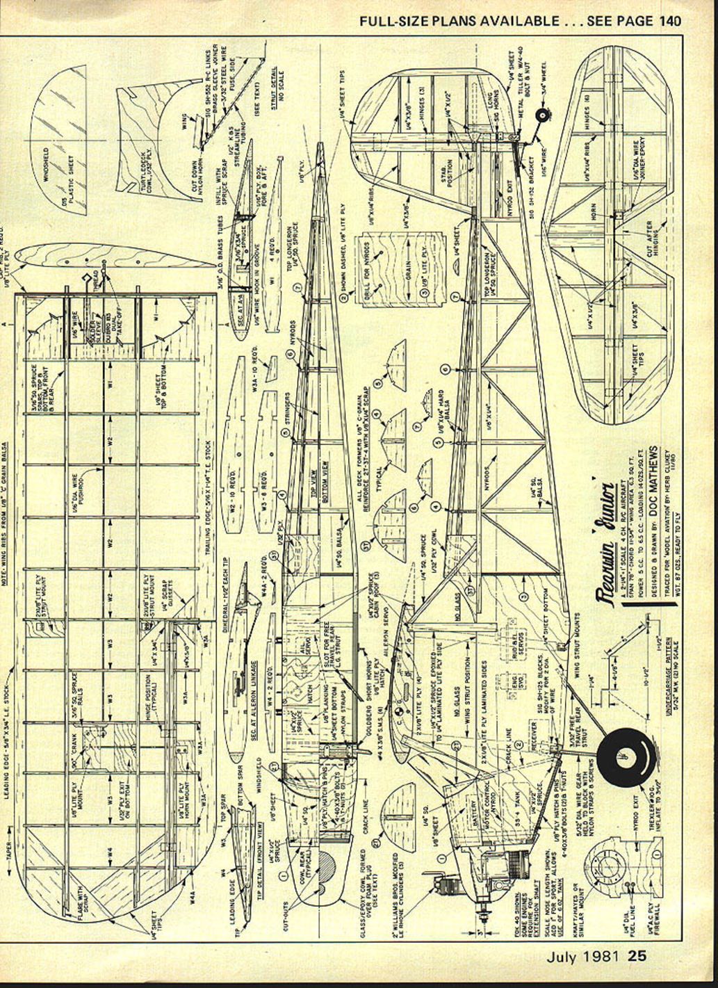
The full-size airplane that this model is patterned after was one of several variations on a basic theme that appeared in the early Thirties. The model is purely intended for RC sport flying—and it's great at that—but with a readily identifiable scale appearance. For .30–.40 engines, four channels. Dee B. Mathews.
The Rearwin Junior is an interesting design in that it was marketed in five different forms by four separate manufacturers. Originally designed by Noel Hockaday as a last-ditch effort to keep Ed Porterfield's American Eagle Co. afloat, only 90 of the Eaglet units were sold before the company was liquidated in 1931.
At the same moment in history, Rearwin Aircraft was manufacturing the Ken-Royce biplane across the river in Kansas City, KS. R. A. Rearwin had been a successful building-supply dealer in Salina, KS. In 1928 he had gone into production of the biplane named after his two sons. He moved his facilities to Kansas City in 1929, sharing half of a newly constructed building at Fairfax Airport with the makers of the Inland Sport Monoplane.
By the end of 1930, the Great Depression had curtailed Ken-Royce sales to only five for the entire year. Seeking to remain in business, Rearwin decided to build a small tandem-seated trainer which would sell at a profit for $1,500. Engineers Doug Weber and Noel Hockaday were hired to design and build a 500-lb. monoplane to be powered with a 45-hp Szekely motor. Dubbed the Junior, it was—for all practical purposes—a refinement of the Eaglet. The prototype first flew in the spring of 1931.
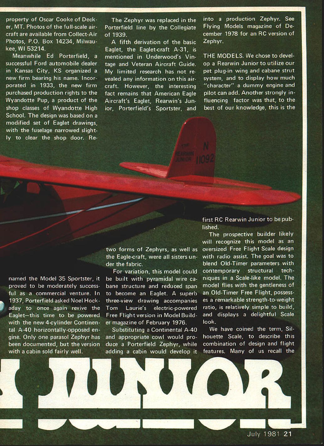
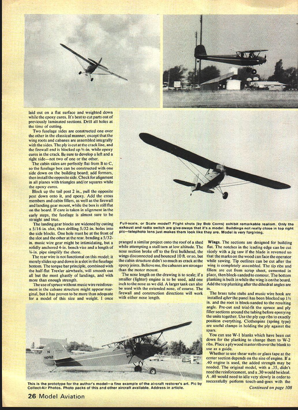
The Junior differs only slightly from the Eaglet. Its cabane structure is of vertical rather than pyramidal tubing and the center section added 19 in. to the total wingspan. All other dimensions and outlines are identical. The Junior was certified with the Szekely in July 1931 and was placed into limited production. It was reputed to be docile, sturdy, and reliable, but the ultra-light aircraft market had been cornered by Aeronca's C-3 and Curtiss Wright's Junior pusher. A total of only 23 Rearwin Juniors were constructed, with just one now remaining airworthy. The prototype of the author's model, N11092, is the property of Oscar Cooke of Decker, MT. Photos of the full-scale aircraft are available from Collect-Air Photos, P.O. Box 14234, Milwaukee, WI 53214 (set No. 136).
Meanwhile Ed Porterfield, a successful Ford automobile dealer in Kansas City, KS, organized a new firm bearing his name. Incorporated in 1933, the new firm purchased production rights to the Wyandotte Pup, a product of the shop classes of Wyandotte High School. The design was based on a modified set of Eaglet drawings, with the fuselage narrowed slightly to clear the shop door. Renamed the Model 35 Sportster, it proved moderately successful commercially. In 1937, Porterfield asked Noel Hockaday to once again revive the Eaglet—this time to be powered with the new 4-cylinder Continental A-40 horizontally opposed engine. Only one parasol Zephyr has been documented, but the version with a cabin sold fairly well. The Zephyr was replaced in the Porterfield line by the Collegiate of 1939.
A fifth derivation of the basic Eaglet, the Eagle-craft A-31, is mentioned in Underwood's Vintage and Veteran Aircraft Guide. Limited research has not revealed further information on this aircraft. The interesting fact remains that American Eagle Aircraft's Eaglet, Rearwin's Junior, Porterfield's Sportster, two forms of Zephyrs, and the Eagle-craft were all sisters under the fabric.
For variation, the model could be built with a pyramidal wire cabane structure and reduced span to become an Eaglet. Tom Laurie's electric-powered free-flight version in Model Builder (February 1976) includes a superb three-view. Substituting a Continental A-40 and appropriate cowl would produce a Porterfield Zephyr, and adding a cabin would develop it into a production Zephyr. See Flying Models (December 1978) for an RC version of the Zephyr.
We chose to develop a Rearwin Junior to utilize a plug-in wing and cabane strut system and to display how much "character" a dummy engine and pilot can add. To the best of our knowledge, this is the first RC Rearwin Junior to be published.
Prospective builders likely will recognize this model as an oversized free-flight scale design with radio assist. The goal was to blend Old-Timer parameters with contemporary structural techniques in a scale-like model. The model flies with the gentleness of an Old-Timer free flight, possesses a remarkable strength-to-weight ratio, is relatively simple to build, and displays a delightful scale look.
We have coined the term Silhouette Scale to describe this combination of design and flight features. Many remember the small black silhouettes used during WWII to train air crews, anti-aircraft gunners, and ground spotters to recognize aircraft shapes. These models were not highly detailed, nor elaborately finished, but were instantly recognizable. The concept carries into this Rearwin Junior model: outlines, shape, and general appearance are instantly identifiable, but the model is not highly detailed nor dimensionally absolute to scale. The design provides a scale silhouette while accepting modest enlargements—an enlarged stabilizer, increased dihedral, and slight increase in wing chord—to improve docility and handling without affecting the full-scale illusion at distance.
Construction
Since anyone who has constructed an Old-Timer or free-flight scale model should not encounter difficulty with this model, the focus here is on the unusual and novel aspects of construction rather than a part-by-part description.
Engine cowl (foam plug and glass/epoxy method)
The cowl is simple to fabricate with the foam-plug, epoxy-and-glass technique.
- Rough-cut a plug from one-pound polystyrene foam (Sig or equivalent). Tack-glue it to the firewall with 5-min. epoxy. Carve the plug to shape with knife and sandpaper; it need not be perfectly smooth, only well shaped.
- Remove the plug and coat it with a layer of Hobbypoxy Formula One or Devcon 30-min. epoxy to provide a firm surface for fiberglass.
- Cut gores (football-section shapes) to fit the plug. Avoid using one large gore over multiple sharp contours—use several smaller gores.
- Use heavyweight fiberglass cloth (marine/body repair type) rather than narrow model reinforcement tape. Heavyweight cloth is available at marine-supply outlets.
- Mix epoxy and spread a thin coat on the plug where the gore will lie. Lay the pre-cut gore onto the epoxy, flatten/contour it with plastic wrap, then remove the wrap and smooth the epoxy with a moist finger (saliva works; clean hands with butyrate thinner).
- Apply additional gores until the plug is completely covered. Sand overlaps to a feather edge after cure using #60–#100 aluminum-oxide paper.
- Repeat build-up until most areas have at least three layers of fiberglass, with a fourth layer in high-stress areas. Sand the final layer with #220 paper.
- Spread a final large batch of epoxy over the complete surface—apply more toward the nose to avoid pushing epoxy aft.
- Inflate a large rubber balloon and press it over the epoxy-coated plug so it covers the rear to excess. Slowly deflate the balloon so the back folds under the plug; allow epoxy to cure, then peel off the balloon. If small voids remain, fill them with microballoons in epoxy or Hobbypoxy P.F.C.
- Remove the foam from inside the cowl with a spoon; remaining pieces dissolve in thinner or gasoline (perform outdoors and dispose of residues safely).
This "EZ-does-it" technique (pioneered by Hobbypoxy) yields an attractive, durable cowl that is usually less expensive and simpler than a block-balsa unit.
Dummy cylinders and detail:
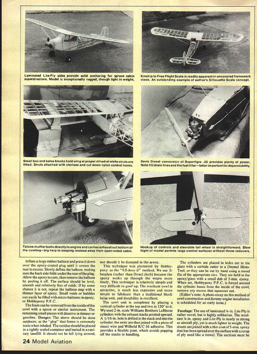
- Place a vertical cylinder at the top and two at 120° intervals. We used 2-in. scale Williams Brothers LeRhone cylinders with exhaust stacks upward.
- Drill a 1/16-in. hole in each stack and into the cylinder; join stacks with a piece of music wire and R/C 56 adhesive to provide a flexible joint.
- Cut holes in the glass for the cylinders with a carbide cutter in a Dremel or a suitable round file. Bond cylinders to the epoxy/glass with 5-min. epoxy and force Hobbypoxy P.F.C. around the bases from inside the cowl.
(Editor’s note: a photo essay on this cowl-and-dummy-engine method is scheduled for a future issue.)
Fuselage
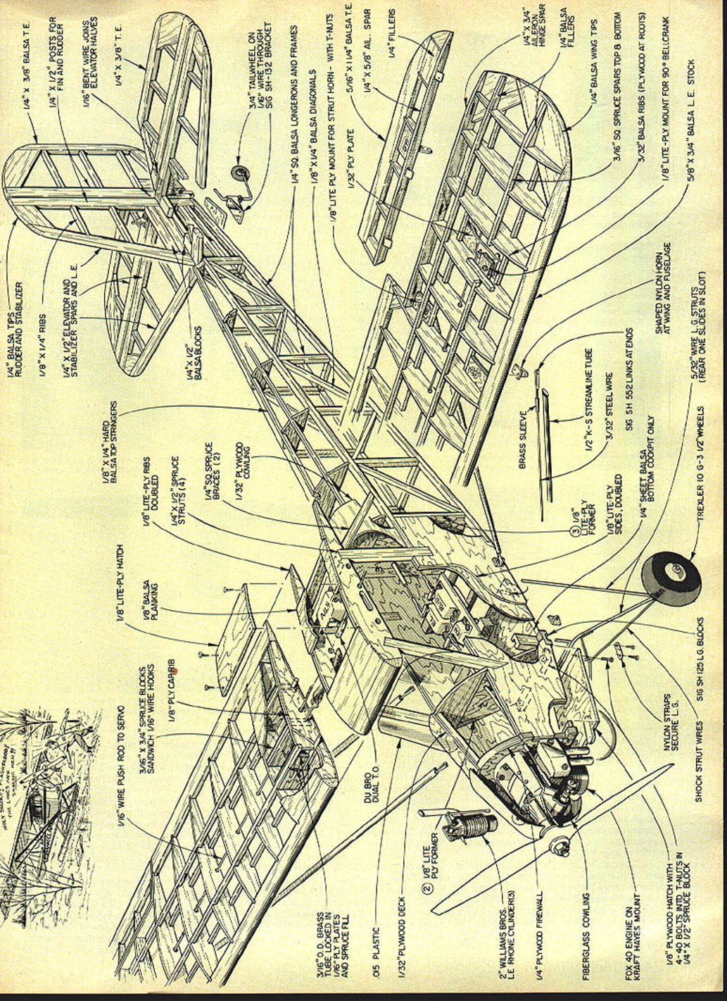
- Use laminated 1/8-in. Lite-Ply joined with a thin coat of 5-min. epoxy spread with a scrap ply trowel. Carefully align and clamp while the epoxy cures. The laminated Lite-Ply sides provide solid anchoring for the spruce cabin superstructure; the result is nearly as strong as aircraft ply but much lighter.
- Use Lite-Ply for floors and bulkheads for rigidity and easy control installation. Stringers and planking are standard balsa construction.
- Provide hatch and access panels for servicing radio and battery. Install controls with clevises and cut-down nylon control horns; hookup of controls and steerable tailwheel is straightforward. Slow flight permits large control surfaces without throw reducers.
- Build two fuselage sides one over the other on the building board, assembling wing roots and cabanes integrally with the sides. Cut the ply at the crack line and block up the firewall end 5/16-in. while epoxy cures in the crack—ensure left and right sides, not two of one side.
- Cabin sides are perfectly flat between stations B and C, so build the fuselage box with one side flat on the board; add formers then install the opposite side. Check alignment in all planes while epoxy cures.
- Block up the tail post 2 in., pull the opposite post down onto it and epoxy. Add cross members, cabin fillers, firewall and landing gear mount while the box is still flat.
- Landing gear blocks: widen by cutting a 5/16-in. slot, then drill 5/32-in. holes into side blocks (one at the front of the slot and one at the rear). Bend a 5/32-in. music-wire gear using a bench vise and pipe as a former.
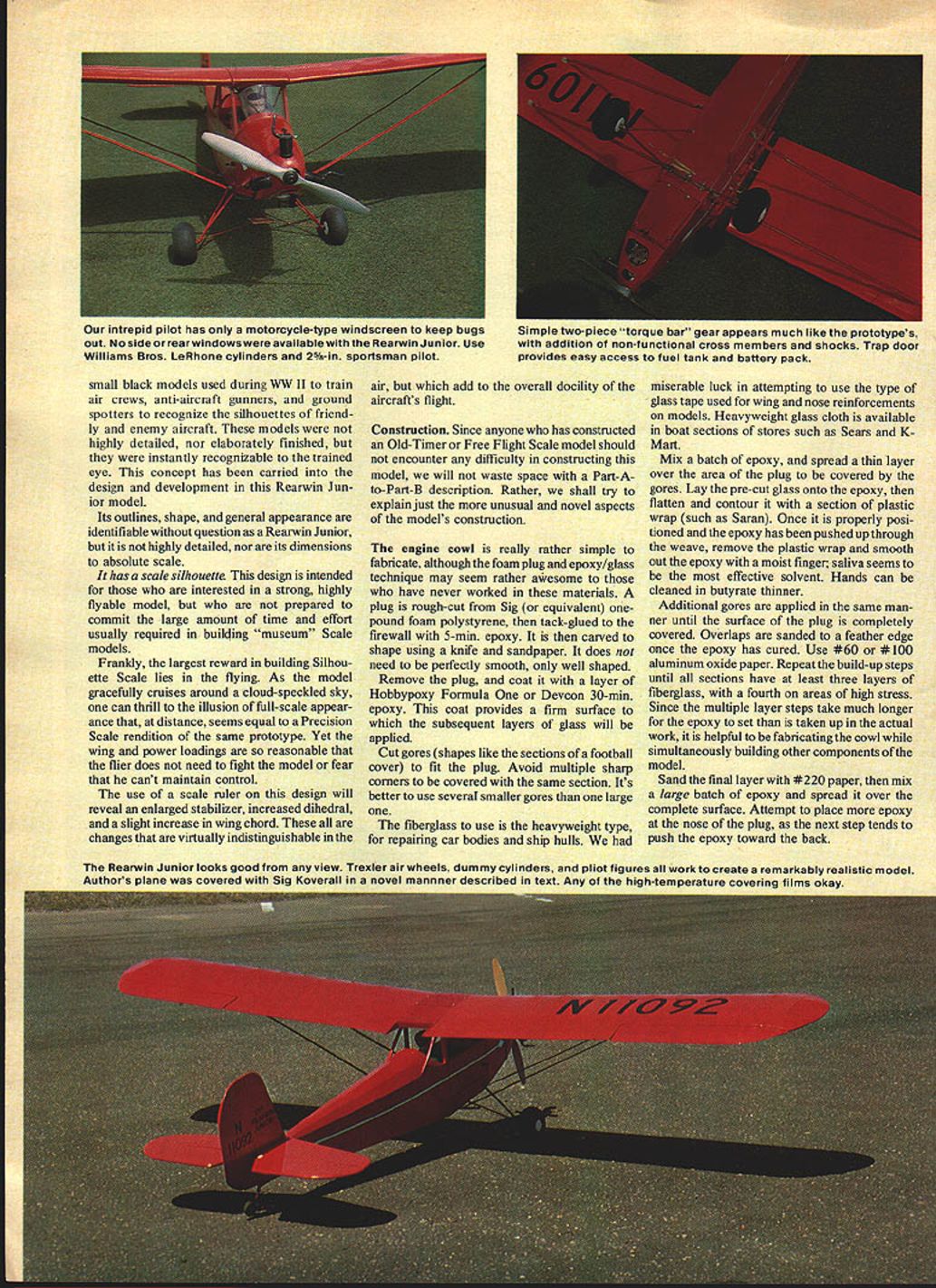
- The rear wire on this model is not functional; it slides in a slot in the fuselage bottom. The torque-bar principle combined with half-flat Trexler airwheels smooths out landings.
- Spruce cabane members without additional music-wire reinforcement have proven adequate; epoxy joints in the cabin structure are robust under heavy loads.
Wings
- Wing panels are built flat. Leading-edge notches can be cut with a jigsaw (blade reversed so marks face the operator). Tip outlines are cut after assembly.
- Tip ribs and fillers: cut from scrap sheet, cement in place, then block-sand to contour.
- Build bottom planking while wing is on the board. Add top planking after setting dihedral.
- Install brass tube stubs and music-wire hook after blocking the panel up 1-1/2 in. and block-sanding the root to the resulting angle. Pre-cut and trial-fit spruce and ply filler sections around tubing before epoxying. Use ply cap ribs to position parts; clothespins are handy clamps.
- You can convert W-1 blanks to W-2 ribs by cutting them down and using a plywood master as a guide.
- Whether to use shear webs or glass tape at the center section depends on engine size. A .40 engine may require added strength; the original model with a .35 did not. A .30 is ideal; a .40 will need to idle very slowly for touch-and-goes.
- Struts are functional and simple: solder Sig SH-552 heavy-duty clevises and rods onto 3/32-in. music wire using short brass-tube joiners. Fit clevis/wire lengths with the wing panel blocked to proper dihedral, then solder joints. Crimp small tin tabs to the wire, solder, trim to slide into K&S airfoil tubing, and secure with P.F.C. formed around the tabs to prevent rotation.
- All nut plates for cut-down horns should be secured inside with Hot Stuff or epoxy before covering, as access will be lost after covering.
- Clevises on horns allow some rigging adjustment (washout/washin) and make wing attachment simple. Always use two rubber bands between the hooks as a safety measure.
Radio installation
- Install hardware after structure completion. Adjust the servo tray fore and aft to obtain a center of gravity (C.G.) approximately 1-1/2 in. ahead of the finished point to allow for covering and finish weight aft of the C.G.
- Secure a 3/8 x 3/4-in. bass or spruce cross beam permanently to the fuselage sides with sheet-metal screws through the ply sides.
- Place the receiver under the servos or in a scrap ply box forward of them, whichever helps achieve proper C.G.
- Use anti-flex cross members every six inches or so in the pushrod runs. We used Sullivan semi-flex pushrods, threaded clevis studs on horn ends, and EZ connectors on servo ends.
- Threaded studs can be installed into nylon pushrods by chucking them in a 1/4-in. drill and "blipping" them into the rod.
- Aileron linkage: Du-Bro #183 ball-link connectors worked well for quick wing removal. Turn the connector all the way up on one threaded rod to remove the wings; practice yields removal and installation in a minute or two.
Covering and finish
- The prototype used Sig Koverall applied in a novel manner: paint framework outlines with two coats of 50% water/50% Elmer's white glue, let dry, then iron on the Koverall. Use the iron at the Coverite temperature to draw the glue into the fabric weave; this secures the edges and allows shrinking. Overlap areas require a repeat coat on the first surface before the second is applied.
- Koverall will seal and fill with two or three coats of K&B nitrate dope and accepts polyurethane paints without blistering or peeling.
- Wings and tail can be covered with Koverall for durability and strength, but MonoKote or similar films are acceptable for those surfaces; check film temperature ratings where applicable.
- Any high-temperature covering film is OK for other surfaces. Add cowl detail, dummy cylinders, pilot figures and Trexler air wheels for a realistic appearance. A motorcycle-type windscreen suits the intrepid pilot. Provide a trap door for easy access to the fuel tank and battery pack.
Flying
- Conduct a thorough systems check at home at a leisurely pace. When ready, take the Rearwin Junior to the flying field.
- Ground handling is not squirrely for a taildragger. Advance throttle slowly until the rudder gets airflow; the airplane will break ground with little need for up elevator.
- Rudder-only turns are gentle; hold slight opposite rudder to level the wings. With ailerons, some opposite rudder may be needed to counteract dihedral (particularly in left turns).
- Landings are slow and gentle: line up with the runway about 150 ft. out and hold until flying speed is lost and the airplane settles onto the grass. You may need down elevator to get the wheels onto the grass. The Junior tends to bounce if a three-point attitude is held with too much speed on takeoff.
- Stalls are mushy; no tendency to spin has been observed. The model has no tendency to snap at low speed or to pitch at high speed. It flies like a heavy Old-Timer with RC assist—predictable and forgiving.
- This airplane can be flown by anyone with some Old-Timer stick time. The construction is simple but strong, it flies beautifully, and it is realistic in the air. Enjoy.
References
- Aviation History in Greater Kansas City, Cub Flyers Publications, Library of Congress Catalog No. 74-119630.
- Lightplanes Since 1909, John Underwood and George Collinge, Heritage Press, Library of Congress Catalog No. 69-17709.
- Air Progress, January 1968. "Those Wonderful Rearwins — Some Giant Birds," by John W. Underwood.
- The Vintage and Veteran Aircraft Guide, John Underwood, Collinwood Press, Library of Congress Catalog No. 68-28978.
- Collect-Air Photos, P.O. Box 14234, Milwaukee, WI 53214, set No. 136.
Transcribed from original scans by AI. Minor OCR errors may remain.

