
Receiving Converters for RC Frequencies
If you've done some electronics work and can find your way around a schematic, here's a building project for a useful device: a converter that allows you to listen to your RC frequency on a portable radio. Every club should have one!
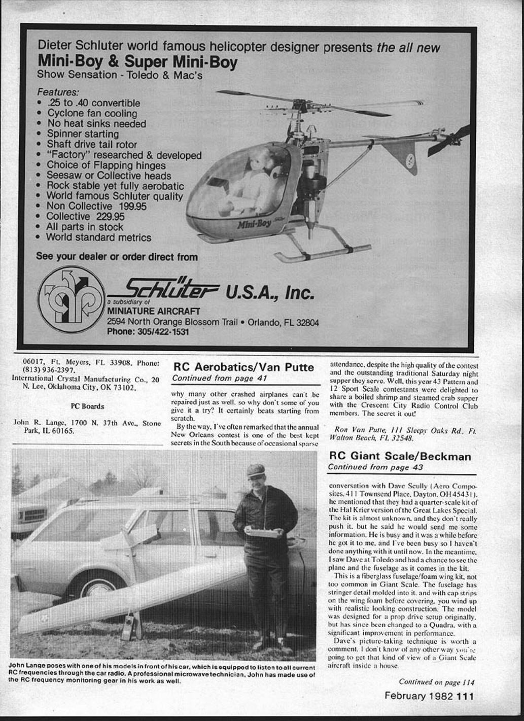
John R. Lange
Would you like to be able to monitor your RC frequency before you fly, chase down interference, check for glitches? Would you like to be sure that someone else's transmitter, in the impound area or in a car, hasn't been left on? If you get glitched, would you like to be sure it was interference that got you?
I am a ham radio operator, and I fly RC on 6 meters (53 MHz). I wanted to check the band before flying, since 6 meters can be infested with ignition engine noise, amateur FM repeaters, and other signals. To do so, I developed this receiving converter from circuits in the ARRL Radio Amateur's VHF Manual. Anyone who has built a Heathkit or Ace kit ought to be able to build one. Most parts can be obtained from your local Radio Shack store; the receiving crystals can be mail-ordered from JAN Crystals or International Crystals (addresses appear in the original publication).
This receiving converter can be built in either of two ways:
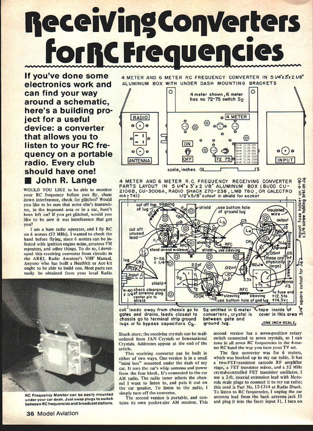
- A small "mini box" mounted under the dash of a car. It uses the car's whip antenna and power from the fuse block and is connected to the car AM radio. The radio tuner selects the channel you want to listen to; the converter is switched on to hear RC signals and off to hear normal AM broadcasts.
- A portable unit containing its own pocket-size AM receiver. This version uses a seven-position rotary switch connected to seven crystals so you can select the RC frequency like tuning a radio.
The first converter I built for 6 meters was hooked to my car radio. It uses a two-FET cascode RF amplifier stage, a FET mixer, and a crystal-controlled FET oscillator. I use a 2-ft coaxial extension lead with Motorola male plugs to connect to the car radio (Radio Shack part no. 12-1314). To listen to RC frequencies, unplug the car antenna lead from the radio antenna jack and plug it into the converter input J1. Turn on the converter and tune the car radio to the appropriate AM dial range (1100–1500 kHz for 53.1–53.5 MHz). I preset two radio push-buttons for the two RC frequencies I use so I can switch quickly.
The 4-meter converter (72–76 MHz) works the same way. It can pick up all seven RC frequencies with only two receiving crystals in many cases. Since the first six frequencies between 72.080 and 72.960 MHz are less than 1 MHz apart, a 71.400 MHz crystal in the converter local oscillator will allow you to tune all of them between about 540 and 1600 kHz on your AM dial. The seventh frequency, 75.640 MHz, is picked up by switching to a 74.640 MHz crystal; it then appears at 1000 kHz on the dial.
The portable converter uses a small under-$10 Radio Shack AM pocket radio (catalog numbers 12-171 or 12-172) tuned to 1000 kHz. All seven receiving crystals in the portable converter are 1 MHz below the corresponding RC frequencies and are mounted on the poles of a rotary switch. A nine-volt battery in series with two AA cells provides the approximately 12 V needed by the converter; the pocket radio has its own battery.
You can also build the circuit into an aluminum box or chassis with a small car radio and whip antenna, powered by a 12 V Gel Cell or Ni-Cad pack. This eliminates occasional AM broadcast interference when stations are close to the converter output dial positions.
Construction
- The under-dash version is built in a 5-1/4 x 3 x 2-1/8 in. aluminum box. The portable version is built in a 10 x 6 x 2 in. aluminum chassis with a bottom cover.
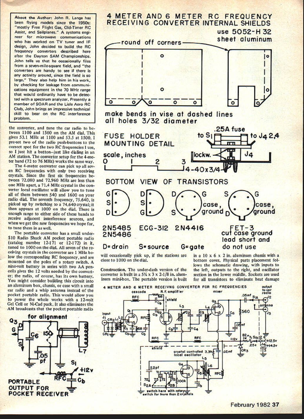
- Physical parts placement follows the schematic: inputs to the left, outputs to the right, and oscillator section in the lower middle. Use sockets for all transistors to avoid heat damage.
- Shorten transistor leads about 3/16 in. for better fit in sockets and to reduce the chance of jars pulling them out. Since transistors have different lead connections, orient them carefully after checking bottom views. Plug in transistors only after all wiring and soldering is finished and with power off.
- Use aluminum shielding to isolate input and output RF amplifier coils and the oscillator compartment. Cut shielding from sheet aluminum and install after most parts are mounted. Drill 1/4-in. holes in shielding for the power and oscillator injection leads and mixer connections. Use sleeving or heat-shrink tubing on long component leads.
- Two reverse-connected 1N914 diodes are wired across the input terminals for protection against excessive input signals.
- No printed circuit boards are necessary; wiring is point-to-point between sockets and miniature terminal strips mounted with 2-56 screws, nuts, and lock washers. Trim excess lugs from terminal strips as needed.
- Keep component lead lengths to a minimum, especially for small bypass capacitors and C6. Keep the gate lead of Q2 as short and direct as possible.
- In the portable unit, couple the mixer output to the ferrite rod antenna of the pocket radio by wrapping eight turns of shielded wire around the antenna. Shield the interconnecting lead with braid or use short 2-conductor shielded wire to minimize interference from AM broadcast stations near the radio dial setting.
- All iron-core tuned coils are wound on 1/4-in. diameter forms (Miller 45004 or similar). Coils and RF chokes are wound with enamel- or nylon-coated solid copper magnet wire. Tin wire ends before fastening to resistor leads. File a 1/16-in. notch in opposite edges of a 1-watt resistor to help keep wire from unraveling. Secure start and finish turns and paint coils with polystyrene dope (do not use ordinary model cement unless polystyrene type).
- In the 4-meter converter, L5 (with its output link L6) is used for all switched crystal frequencies. Some weak crystals/transistors may not oscillate across the full frequency spread; a switched-in 2.2 pF capacitor for the lower frequencies can correct this. Route all crystals to a common ground lug under a switch mounting post nut; tie the common rotary switch contact directly to the gate of Q4. Place the switch as close to Q4 as possible to minimize stray capacitance and inductance. The second gang of the switch can switch in the 2.2 pF capacitor.
Alignment
- Connect the radio to J2 and set the radio volume so you can hear background noise.
- Turn on the converter. The noise should increase. Adjust the iron core in L5 until the noise increases to a maximum.
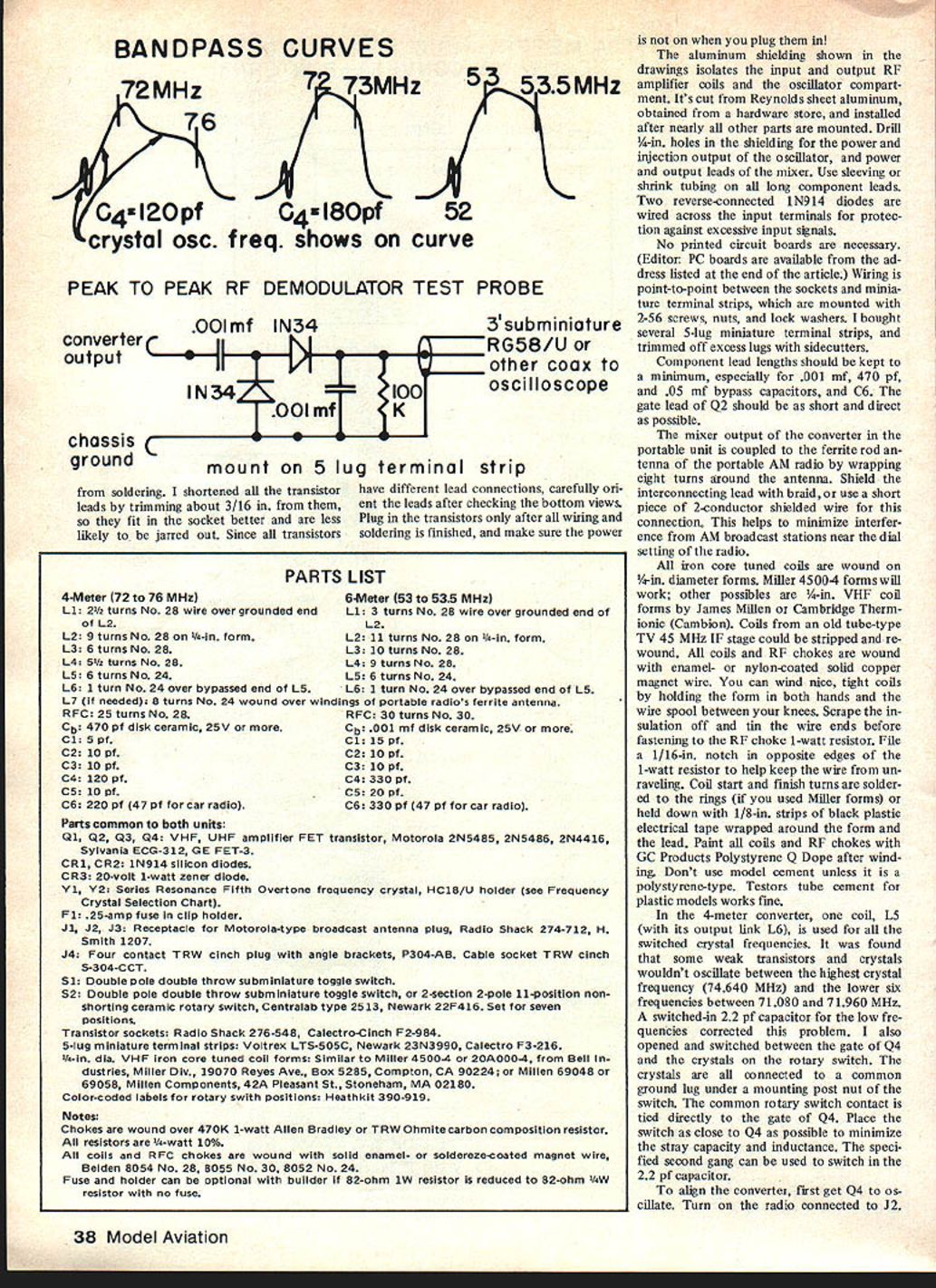
- Verify each crystal oscillates when switched. Using a peak-to-peak demodulator test probe connected to a scope or DVM, touch the probe to the output link L6 and chassis ground. You should obtain about 0.2 V or better; adjust L5 for the highest reading just before the oscillator quits (often about 0.8–1.0 V).
- If no oscillation, reduce coupling of L6 to L5 by spreading L6 or sliding it below the bypassed end of L5. If still no oscillation, remove the iron core from L5 and slowly insert a brass screw into the end of the coil; if oscillation occurs the coil is too large — spread the windings or remove a turn and recheck.
- Connect a short whip or ~1 ft wire to input J1. Turn on an RC transmitter (antenna collapsed), the AM radio, and the converter. Tune to the transmitter buzz and adjust L2, L3, and L4 iron cores for maximum output. L2 tunes broadly; L3 and L4 more sharply. Make sure both a 72 MHz and 75 MHz transmitter can be heard.
- For sharper indication, use a scope and the demodulator probe on output J2 or the drain of Q3. You may improve scope indication by temporarily removing L7 and placing a 150-ohm resistor in its place.
Parts List
4-Meter (72 to 76 MHz)
- L1: 2-1/2 turns No. 28 wire over grounded end of L2.
- L2: 9 turns No. 28 on 1/4-in. form.
- L3: 6 turns No. 28.
- L4: 5-1/2 turns No. 28.
- L5: 6 turns No. 24.
- L6: 1 turn No. 24 over bypassed end of L5.
- L7 (if needed): 8 turns No. 24 wound over windings of portable radio's ferrite antenna.
- RFC: 25 turns No. 28.
- Cb1: 470 pF disk ceramic, 25 V or more.
- C1: 5 pF.
- C2: 10 pF.
- C3: 10 pF.
- C4: 120 pF.
- C5: 10 pF.
- C6: 220 pF (47 pF for car radio).
6-Meter (53 to 53.5 MHz)
- L1: 3 turns No. 28 wire over grounded end of L2.
- L2: 11 turns No. 28 on 1/4-in. form.
- L3: 10 turns No. 28.
- L4: 9 turns No. 28.
- L5: 6 turns No. 24.
- L6: 1 turn No. 24 over bypassed end of L5.
- RFC: 30 turns No. 30.
- Cb1: 0.001 µF disk ceramic, 25 V or more.
- C1: 15 pF.
- C2: 10 pF.
- C3: 10 pF.
- C4: 330 pF.
- C5: 20 pF.
- C6: 330 pF (47 pF for car radio).
Parts common to both units
- Q1, Q2, Q3, Q4: VHF/UHF amplifier FET transistors — examples: Motorola 2N5485, 2N5486, 2N4416; Sylvania ECG-312; GE FET-3.
- CR1, CR2: 1N914 silicon diodes.
- CR3: 20-volt, 1-watt zener diode.
- Y1, Y2: Series-resonance fifth-overtone frequency crystals, HC-18/U holder (see Frequency Crystal Selection Chart).
- F1: 0.25-amp fuse in clip holder.
- J1, J2, J3: Receptacle for Motorola-type broadcast antenna plug, Radio Shack 274-712, H. Smith 1207.
- J4: Four-contact TRW cinch plug with angle brackets, P304-AB. Cable socket TRW cinch S-304-CCT.
- S1: Double-pole double-throw subminiature toggle switch.
- S2: Double-pole double-throw subminiature toggle switch, or 2-section 2-pole 11-position non-shortening ceramic rotary switch, Centralab type 2513, Newark 22F416. Set for seven positions.
- Transistor sockets: Radio Shack 276-548, Calectro-Cinch F2-984.
- 5-lug miniature terminal strips: Votex LTS-505C, Newark 23N3990, Calectro F3-216.
- 1/4-in. dia. VHF iron-core tuned coil forms: similar to Miller 45004 or 02000-04 from Bell Industries, Miller Div., or Millen 69048/69056.
- Color-coded labels for rotary switch positions: Heathkit 390-919.
Notes:
- Chokes are wound over 470K 1-watt Allen Bradley or TRW Ohmite carbon composition resistor.
- All resistors are 1/4-watt, 10%.
- All coils and RFC chokes are wound with solid enamel- or solder-coated magnet wire (Belden 8054 No. 28, 8055 No. 30, 8052 No. 24).
- Fuse and holder are optional; builder may omit them at their discretion (observe proper safety practices).
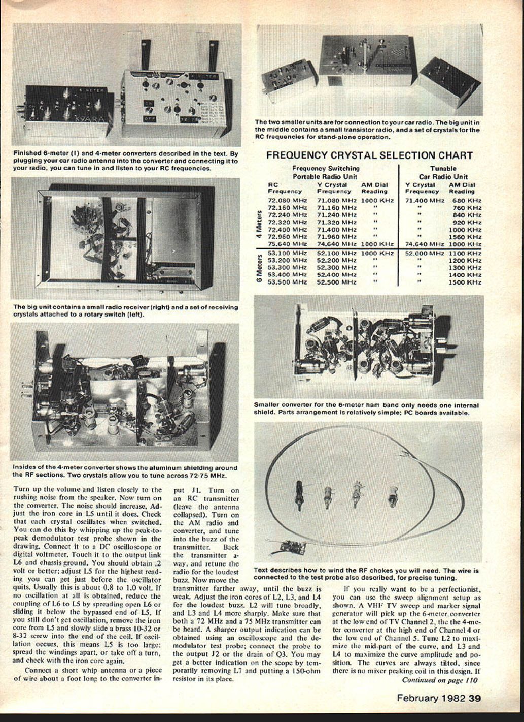
Frequency Crystal Selection Chart
Frequency switching — Portable radio unit (crystals 1 MHz below RC frequency; pocket radio tuned to 1000 kHz unless noted)
4 Meters
- 72.080 MHz — Y crystal 71.080 MHz — AM dial 1000 kHz
- 72.160 MHz — Y crystal 71.160 MHz — AM dial ~1000 kHz
- 72.240 MHz — Y crystal 71.240 MHz — AM dial ~1000 kHz
- 72.320 MHz — Y crystal 71.320 MHz — AM dial ~1000 kHz
- 72.400 MHz — Y crystal 71.400 MHz — AM dial ~1000 kHz
- 72.960 MHz — Y crystal 71.960 MHz — AM dial ~1000 kHz
- 75.640 MHz — Y crystal 74.640 MHz — AM dial 1000 kHz
6 Meters
- 53.100 MHz — Y crystal 52.100 MHz — AM dial 1000 kHz
- 53.200 MHz — Y crystal 52.200 MHz — AM dial ~1000 kHz
- 53.300 MHz — Y crystal 52.300 MHz — AM dial ~1000 kHz
- 53.400 MHz — Y crystal 52.400 MHz — AM dial ~1000 kHz
- 53.500 MHz — Y crystal 52.500 MHz — AM dial 1500 kHz
Tunable car radio unit (examples of AM dial readings for given Y crystal frequencies)
4 Meters
- Y crystal 71.400 MHz — AM dial 680 kHz
- Y crystal 71.160 MHz — AM dial 760 kHz
- Y crystal 71.240 MHz — AM dial 840 kHz
- Y crystal 71.320 MHz — AM dial 920 kHz
- Y crystal 71.400 MHz — AM dial 1000 kHz
- Y crystal 71.960 MHz — AM dial 1560 kHz
- Y crystal 74.640 MHz — AM dial 1000 kHz
6 Meters
- Y crystal 52.000 MHz — AM dial 1100 kHz
- Y crystal 52.100 MHz — AM dial 1200 kHz
- Y crystal 52.200 MHz — AM dial 1300 kHz
- Y crystal 52.300 MHz — AM dial 1400 kHz
- Y crystal 52.500 MHz — AM dial 1500 kHz
Bandpass Alignment with Sweep Generator and Scope
- Connect the ground leads of the sweep generator, the scope, and the converter to an aluminum or copper sheet on the bench.
- Feed the sweep generator output to the converter input through a small coupling capacitor and monitor the converter output on the scope.
- Adjust the tuned input and output coils and trimmer capacitors for a smooth, fairly flat passband centered where desired.
If you do not have a sweep generator, use a signal generator and tune it across the band while monitoring the converter output on the scope or on the AM radio used as the detector.
If available, a VHF TV sweep and marker signal generator will show the 6-meter converter at the low end of TV Channel 2 and the 4-meter converter at the high end of Channel 4 or low end of Channel 5. Tune L2 to maximize the mid-part of the curve and L3/L4 to maximize curve amplitude and position.
4‑Meter and 6‑Meter Converter Setup
- Car converter: Mount under the dash, use the car whip antenna and car radio for audio. Unplug the car antenna lead from the radio and plug the converter output lead into the radio antenna jack. Tune the car radio to the AM dial position corresponding to the converter output frequency. Pre-set radio push-buttons for quick switching.
- The 4-meter converter operates similarly to the 6-meter version and can be set up to receive seven RC frequencies with an appropriate set of crystals on a rotary switch.
Portable Converter
- Contains a pocket-size AM receiver (Radio Shack 12-171 or 12-172) tuned to 1000 kHz.
- Receiving crystals are 1 MHz below the corresponding RC frequencies and are mounted on a rotary switch.
- Power the converter with a 9 V battery in series with two AA cells to provide approximately 12 V; the pocket radio retains its own battery.
Use and Performance
- With a 3- to 5-ft extended whip antenna, the converters are quite sensitive. In tests with a calibrated signal generator, detection at about 0.1 µV was usually possible; 1–3 µV signals were loud and clear.
- With the car engine off and over flat terrain, you can often hear an RC transmitter two to four miles away.
- Best results are obtained with an extended whip antenna for 4 or 6 meters.
Sources for Crystals
- JAN Crystals and International Crystals are commonly used suppliers. Addresses and ordering information appear in the original publication.
Parts and Assembly Notes
- Follow drawings and parts layout for wiring and coil dimensions.
- Use internal shields made from 0.032-in. sheet aluminum (5052‑H32) to keep RF stages isolated and minimize microphony and stray coupling. Round corners and make bends with a vise; drill mounting holes (3/32-in. typical) as required.
- Observe good RF wiring practices, minimize lead lengths, and shield interstage wiring where practical.
Transcribed from original scans by AI. Minor OCR errors may remain.

