
Regent
Ken Willard
Photos by James M. Wade, Jr., Cory Wade, and the author.
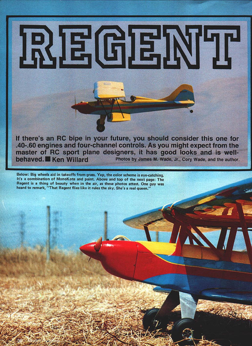
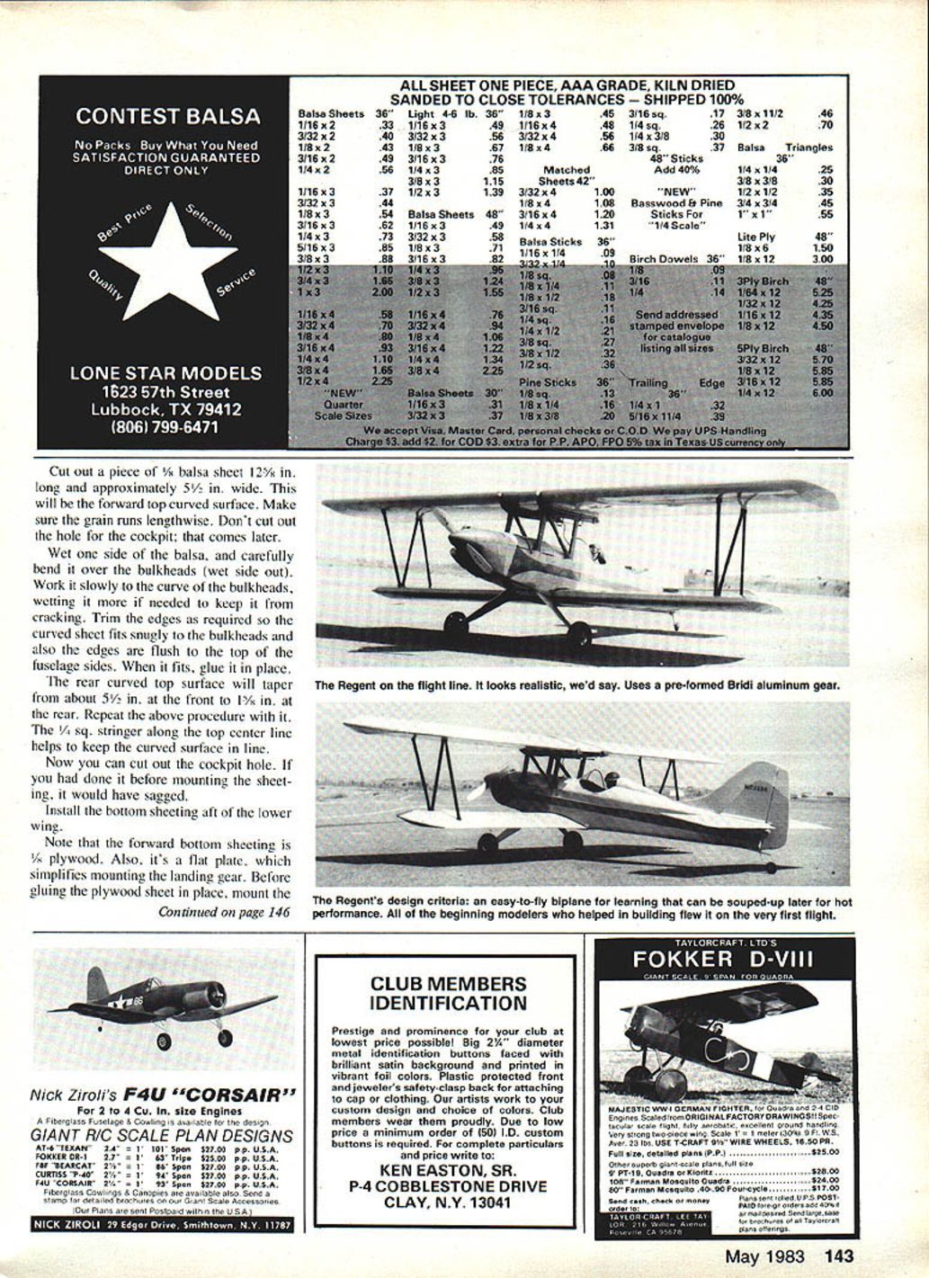
If there's an RC biplane in your future, consider the Regent for .40-.60 engines and four-channel controls. As you might expect from a master of RC sport-plane designers, it has good looks and is well-behaved. Full-size plans available. See page 180.
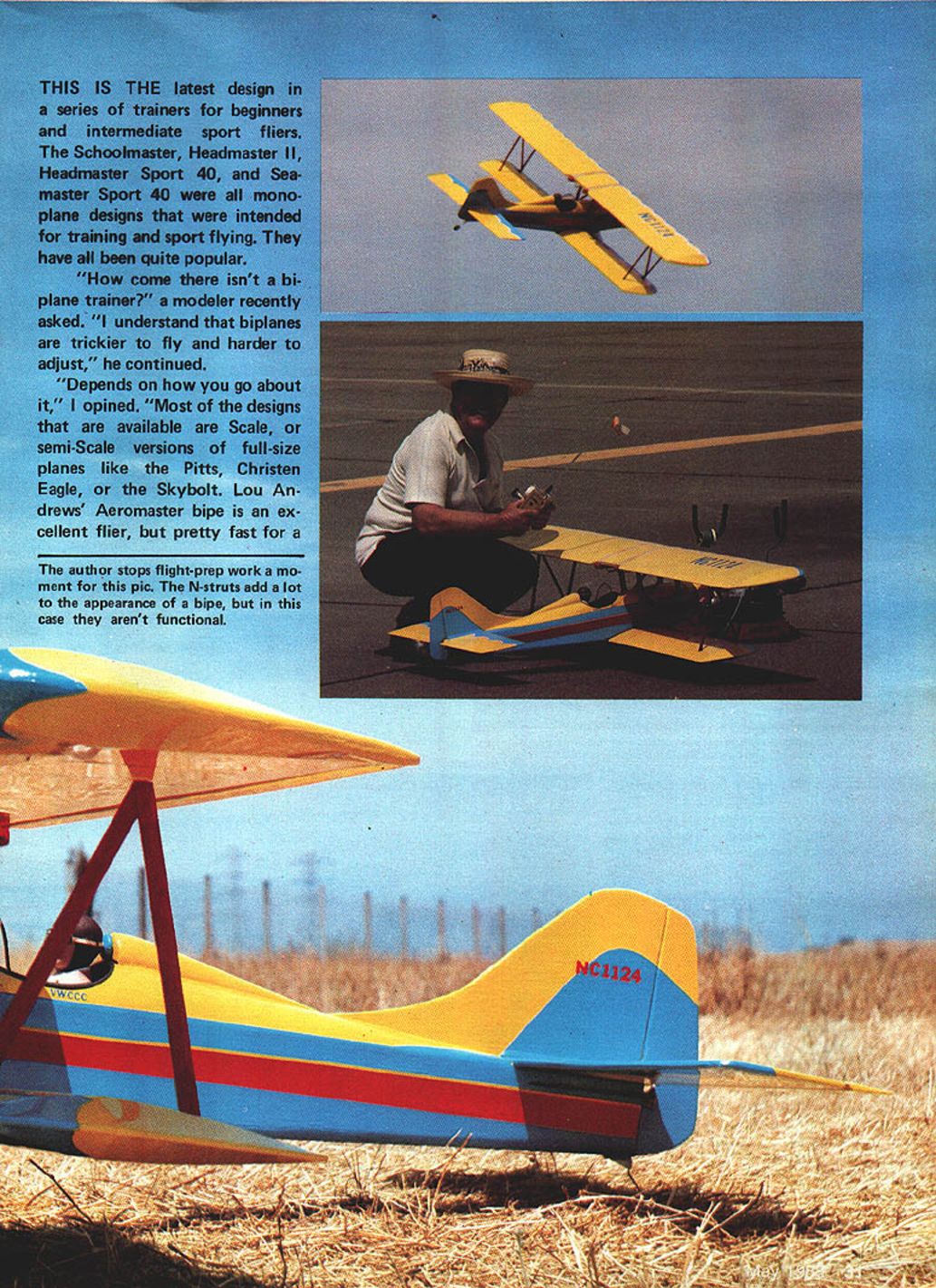
This is the latest design in a series of trainers for beginners and intermediate sport fliers. The Schoolmaster, Headmaster II, Headmaster Sport 40, and Seamaster Sport 40 were all monoplane designs intended for training and sport flying and have been quite popular. A modeler asked why there wasn't a biplane trainer: most available biplanes are scale or semi-scale and tend to be fast. The goal with the Regent was to design a biplane that is easy to build, easy to fly for beginners, and capable of being souped up later for aerobatics.
Design goals included:
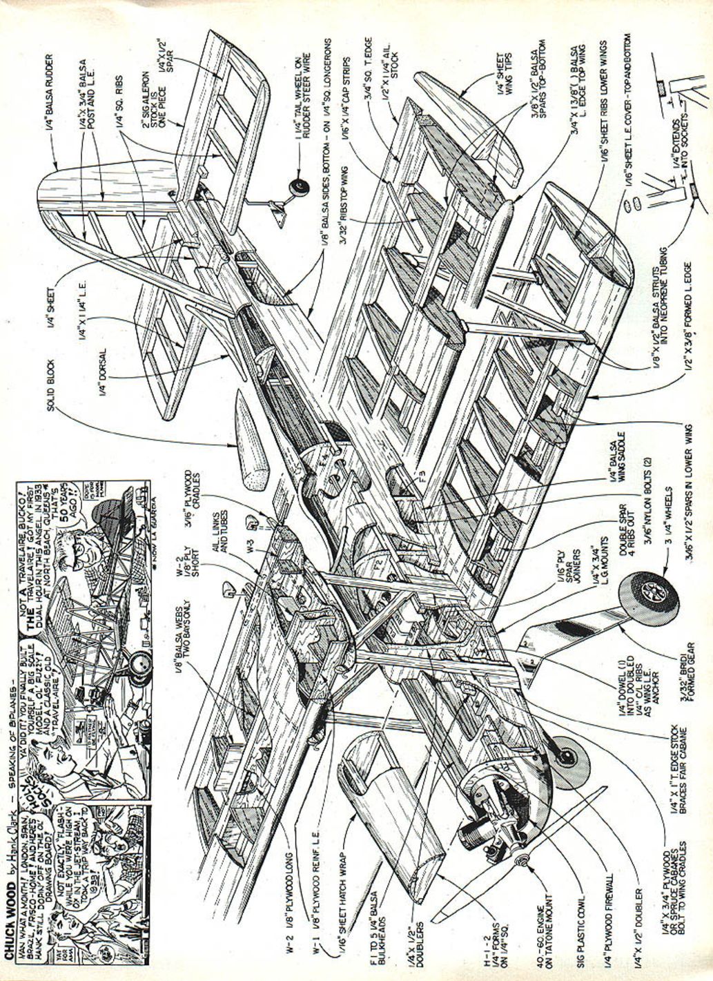
- Simple, conventional balsa and plywood construction (ribs, spars, longerons).
- A simple cabane structure.
- A pleasing, 1930s-era biplane look (Wacos, Pitcairn, Swallow, Travelair).
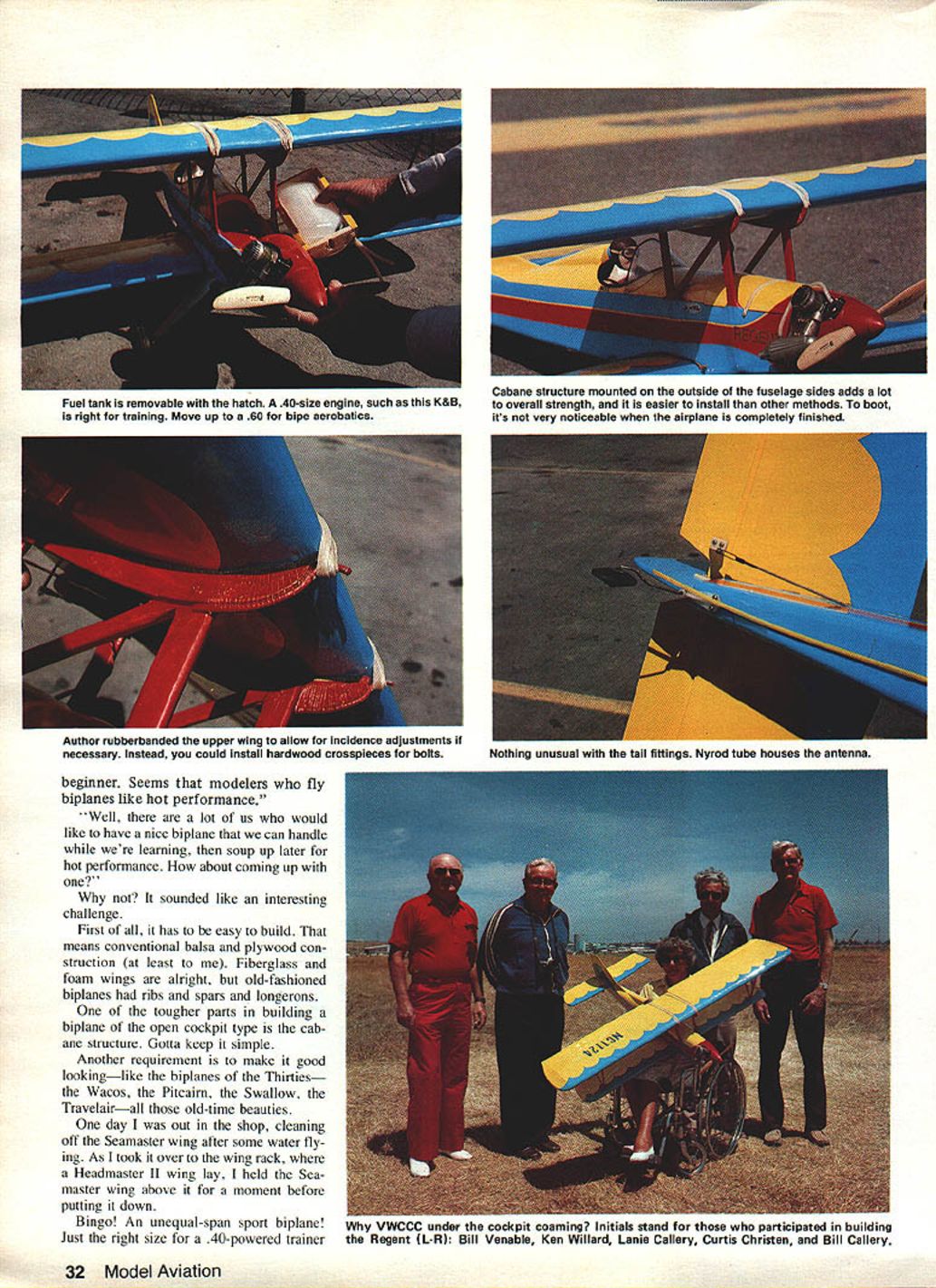
The idea came when a Seamaster wing was held above a Headmaster II wing: an unequal-span sport biplane of just the right size for a .40-powered trainer. A .40-size engine (such as a K&B) is right for training; move up to a .60 for biplane aerobatics — and someone may put a .90 on it.
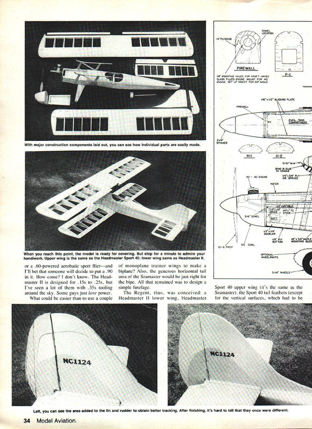
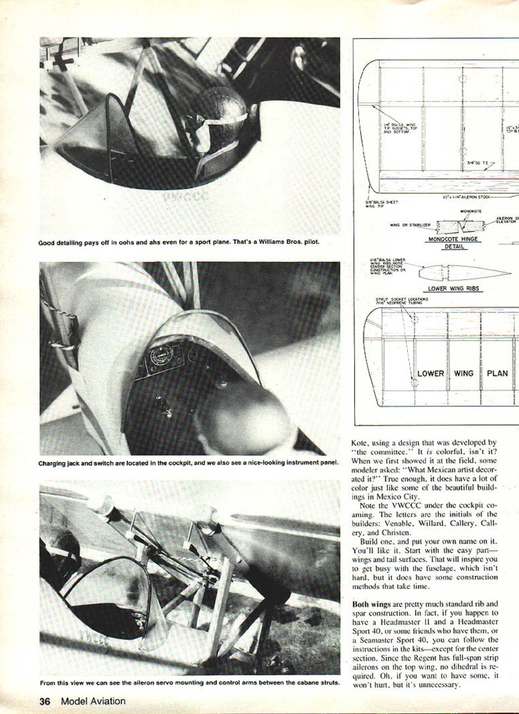
The fuel tank is removable through a hatch. The cabane structure mounted outside the fuselage sides adds strength and is easier to install, and it's a noticeable feature on a finished model. The prototype used rubber bands to hold the upper wing to allow incidence adjustments; hardwood crosspieces and bolts can be used instead. A Nylrod tube houses the antenna wire under the cockpit coaming.
Initials on the plans indicate those who participated in building the Regent: Venable, Willard, Callery, Callery, and Christen (WVCCC).
Design and Construction
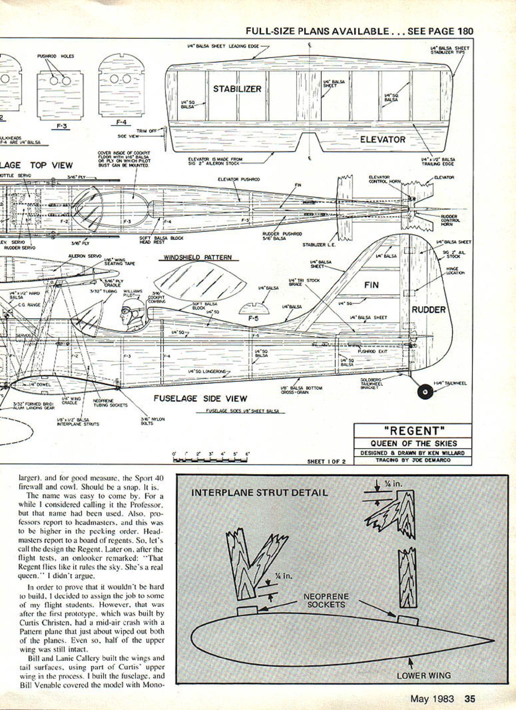
The Regent was conceived as a Headmaster II lower wing with a Headmaster Sport 40 upper wing (the same as the Seamaster), Sport 40 tail feathers (except larger vertical surfaces), and the Sport 40 firewall and cowl. The name came from the hierarchy of school names: Headmaster → regent. After flight tests, someone observed, "That Regent flies like it rules the sky. She's a real queen."
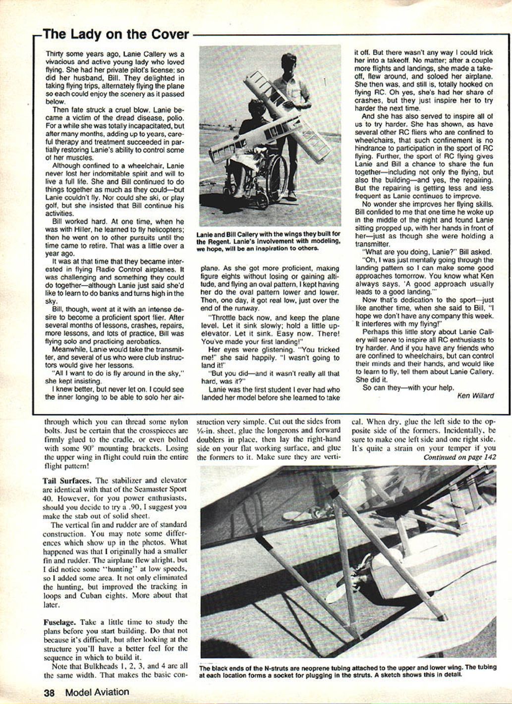
The first prototype was built by Curtis Christen but suffered a mid-air crash with a Pattern plane that almost wiped out both airplanes. Half of the upper wing remained intact and was used in subsequent builds. Bill and Lanie Callery built the wings and tail surfaces (using part of Curtis' upper wing); Ken Willard built the fuselage; Bill Venable covered the model with Monokote.
Build the wings and tail surfaces first to gain momentum. Both wings are standard rib-and-spar construction. If you have existing Headmaster II and Headmaster Sport 40 (or a Seamaster Sport 40), follow those kit instructions except for the center section. The Regent uses full-span strip ailerons on the top wing, so no dihedral is required (dihedral won't hurt, but is unnecessary).
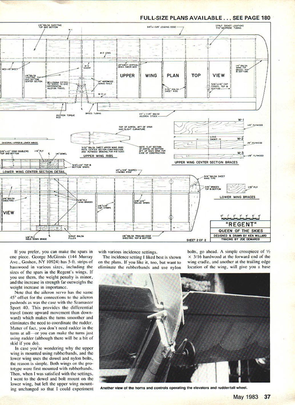
If you prefer, make the spars in one piece. George McGinnis (144 Murray Ave., Goshen, NY 10924) supplies 5-ft. basswood strips in various sizes including the Regent spars; the weight penalty is minor versus the strength gained.
Note the aileron servo has a 45° offset for the connections to the aileron pushrods (same as the Seamaster Sport 40). This provides differential travel (more upward movement than downward), which smooths turns and eliminates the need to coordinate the rudder. In fact, you can turn using aileron only or rudder only (rudder-only turns will have a bit of skid).
Why rubber bands on the upper wing and dowel/nylon bolts on the lower wing? Both wings on the prototype were first mounted with rubber bands. After settling on settings, the lower wing was switched to dowel-and-bolt mounting while the upper wing remained rubber-banded for incidence experimentation. The preferred incidence setting is shown on the plans; if you choose nylon bolts for the upper wing, install 1/2 x 3/16 hardwood crosspieces at the forward and trailing edge cradle locations and thread nylon bolts through them. Ensure crosspieces are firmly glued or bolted; losing the upper wing in flight would be disastrous.
Tail Surfaces
The stabilizer and elevator are identical to the Seamaster Sport 40. If you plan to try a very large engine (e.g., a .90), consider making the stabilizer from solid sheet for strength.
The vertical fin and rudder are standard construction. The original fin and rudder were smaller; the airplane flew but showed some low-speed "hunting." Increasing the fin/rudder area eliminated the hunting and improved tracking in loops and Cuban eights.
Fuselage
Study the plans before starting so you understand the sequence.
- Bulkheads 1–4 are the same width, simplifying construction.
- Cut the fuselage sides from 3/16-in. sheet, glue longerons and forward doublers in place.
- Lay the right-hand side on a flat surface and glue the formers to it, ensuring they are vertical. When dry, glue the left side to the other side of the formers. Be sure to make one left side and one right side.
- Pull the tail ends together and glue to the tailpost. Taper the longerons at the tail per the top view so they fit closely, and ensure both sides have equal curvature to the center line.
Pull the forward ends together and attach the firewall with a slight downthrust. When gluing the firewall to the sides, leave about 1/16 in. of the sides extending beyond the firewall edge so the cowl will be flush with the sides.
At this point, set up the servo mounting rails according to your servos. The illustrated setup is for medium-size servos such as Kraft KPS-14, mounted well forward and close to bulkhead No. 1. On the prototype the servos were placed too far back and required ballast on the firewall. Holes shown in bulkheads for pushrods must be cut to fit your installation.
Rounded top sheeting is in two pieces (not counting the hatch): one from bulkhead No. 1 back to bulkhead No. 4; the second from bulkhead No. 4 back to the stabilizer leading edge.
- Cut a piece of 3/32-in. balsa sheet 12-1/2 in. long and approximately 5-1/2 in. wide for the forward top curved surface; make sure the grain runs lengthwise. Do not cut the cockpit hole yet.
- Wet one side of the balsa and carefully bend it over the bulkheads (wet side out), working slowly and wetting more as needed to prevent cracking. Trim edges so the sheet fits snugly and is flush to the top of the fuselage sides; glue in place.
- The rear curved top sheeting tapers from about 5-1/2 in. at the front to 1-1/2 in. at the rear—repeat the bending procedure. A 1/4-in. square stringer along the top center line helps keep the curved surface aligned.
Now cut out the cockpit hole (doing it after sheeting avoids sagging). Install the bottom sheeting aft of the lower wing. Note that the forward bottom sheeting is 1/8-in. plywood and is a flat plate, which simplifies landing gear mounting.
Here comes a critical part—attaching the upper wing cradle and setting it correctly. Tack-glue the stabilizer and fin assembly to the fuselage, then sight along the fuselage from the front to ensure the wing set in the cradles is parallel to the stabilizer. Check the lower wing cradles as well.
When aligned, glue the cradles to the cabane struts. When dry, drill holes as shown and bolt the cradles to the struts using 6-32 bolts. Install the forward wire mounting hooks and the trailing-edge aligning blocks. The cabane structure is now complete.
Hatch
The hatch comprises two bulkheads, three stringers, and a curved sheet covering—install it like the main fuselage sheeting.
Assembly
The plans show details for tailwheel mount, hinges, firewall engine mount, firewall reinforcing dowels, etc., so narrative descriptions are minimal here. You will likely adapt many fittings to your own preferences.
Examples of possible variations:
- Tank compartment flooring: the author used an oval Sullivan tank laid in at an angle; a square Kress or Kraft tank would require a lower floor.
- Hinges: the prototype used Monokote hinges on the upper wing and stabilizer; you may prefer nylon hinges.
Interplane strut mounting is somewhat unusual but effective. The struts are largely cosmetic (the wings are strong enough without them) and are designed to be instantly removable:
- Struts are fashioned from 1/8 x 1/2-in. balsa and glued together in an "N" configuration. The diagonal end fits between the bottom of the forward strut and top of the rear strut with about 1/8 in. of upright struts extending out.
- A "socket" made from 7/16-in. neoprene tubing is glued with cyanoacrylate to the wing at each strut location. Cut the tubing at an angle to align with the strut.
- When the top wing is placed on the cabane, fit the struts into the sockets; when the wings are firmly in place, the struts are held by the sockets.
Expect to make changes here and there to suit your ideas; many builders adapt the plans.
Finishing
The prototype was built by five people. Bill Venable covered the model, painted the cowl and cabane structure, and used Monokote on the rest. The Regent is colorful—one observer asked, "What Mexican artist decorated it?" You may prefer to paint the entire model; it's the builder's choice.
Flying
Prototype surface movements:
- Ailerons: 3/8 in. up, 1/2 in. down (1/2-in. differential)
- Elevators: 3/8 in. up and down
- Rudder: 1 in. right and left
With these throws, the Regent is gentle but responsive. Beginners who participated in the build actually flew it on the very first flight (though they did not do takeoffs or landings initially).
Capabilities and characteristics:
- Performs rolls, loops, Cuban eights, outside loops, inverted flight, and other aerobatics. It will not perform a vertical torque roll.
- Weighs about 7-1/2 lb with almost 8 sq. ft. of wing area; the prototype weighed over 8 lb with a full tank.
- Takes off easily and climbs rapidly even with a .40 engine.
- Thick wings prevent excessive speed in a dive—good for beginners.
- Glide is slow and steady; wind penetration is good.
- As a taildragger, steering on the ground is a bit more challenging than tricycle gear, but the relatively light wing loading minimizes runway steering difficulties; takeoffs are almost as easy as with trike gear.
You'll like the Regent: it's easy to build, easy to fly, performs well, and looks—and flies—like a queen of the skies.
Transcribed from original scans by AI. Minor OCR errors may remain.

