
REVIEW ECOMRC STINSON RELIANT SR-9
Tom Sullivan tmsullivan@roadrunner.com
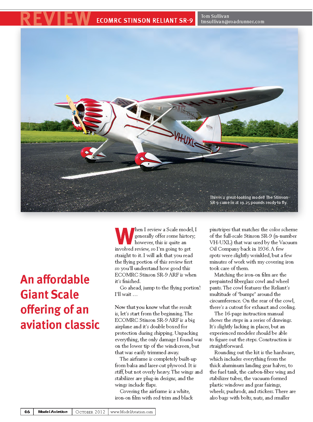
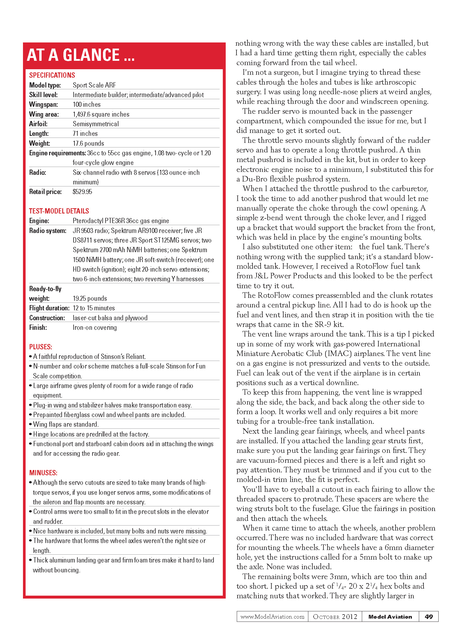
When I review a scale model, I generally offer some history; however, this is quite an involved review, so I'm going to get straight to it. I will ask that you read the flying portion of this review first so you'll understand how good this ECOMRC Stinson SR-9 ARF is when it's finished. Go ahead, jump to the flying portion! I'll wait …
Now that you know what the result is, let's start from the beginning.
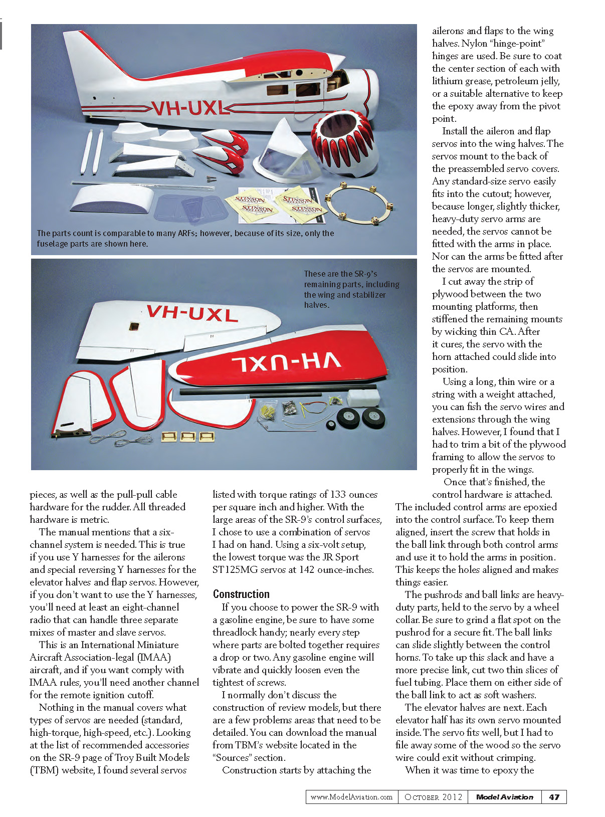
The ECOMRC Stinson SR-9 ARF is a big airplane and it's double boxed for protection during shipping. Unpacking everything, the only damage I found was on the lower tip of the windscreen, but that was easily trimmed away.
The airframe is completely built-up from balsa and laser-cut plywood. It is stiff, but not overly heavy. The wings and stabilizer are plug-in designs, and the wings include flaps.
Covering the airframe is a white, iron-on film with red trim and black pinstripes that matches the color scheme of the full-scale Stinson SR-9 (n-number VH-UXL) used by the Vacuum Oil Company in 1936. A few spots were slightly wrinkled, but a few minutes with a covering iron smoothed them out.
Matching the iron-on film are the prepainted fiberglass cowl and wheel pants. The cowl features the Reliant's multitude of "bumps" around the circumference. On the rear of the cowl there's a cutout for exhaust and cooling.
The 16-page instruction manual shows the steps in a series of drawings. It's slightly lacking in places, but an experienced modeler should be able to figure out the steps. Construction is straightforward.
Rounding out the kit is the hardware, which includes everything from the thick aluminum landing gear halves to the fuel tank, the carbon-fiber wing and stabilizer tubes, the vacuum-formed plastic windows and gear fairings, wheels, pushrods, and stickers. There are also bags with bolts, nuts, and smaller pieces, as well as the pull-pull cable hardware for the rudder. All threaded hardware is metric.
The manual mentions that a six-channel system is needed. This is true if you use Y-harnesses for the ailerons and special reversing Y-harnesses for the elevator halves and flap servos. However, if you don't want to use Y-harnesses you'll need at least an eight-channel radio that can handle three separate mixes of master and slave servos. This is an International Miniature Aerobatic Association (IMAA)-legal aircraft, and if you want to comply with IMAA rules you'll need another channel for the remote ignition cutoff.
Nothing in the manual covers what types of servos are needed (standard, high-torque, high-speed, etc.). Looking at the list of recommended accessories on the SR-9 page of Troy Built Models (TBM), I found several servos listed with torque ratings of 133 oz-in and higher. With the large areas of the SR-9's control surfaces, I chose to use a combination of servos I had on hand. Using a six-volt setup, the lowest torque was the JR Sport ST125MG servos at 142 oz-in.
Construction
If you choose to power the SR-9 with a gasoline engine, be sure to have some threadlock handy; nearly every step where parts are bolted together requires a drop or two. Any gasoline engine will vibrate and quickly loosen even the tightest of screws.
I normally don't discuss the construction of review models in extreme detail, but there are a few problem areas that need to be detailed. You can download the manual from TBM's website (see Sources).
Construction starts by attaching the ailerons and flaps to the wing halves. Nylon "hinge-point" hinges are used. Be sure to coat the center section of each with lithium grease, petroleum jelly, or a suitable alternative to keep epoxy away from the pivot point.
Install the aileron and flap servos into the wing halves. The servos mount to the back of the preassembled servo covers. Any standard-size servo easily fits into the cutout; however, because longer, slightly thicker heavy-duty servo arms are needed, the servos cannot be fitted with the arms in place — nor can the arms be fitted after the servos are mounted.
I cut away the strip of plywood between the two mounting platforms, then stiffened the remaining mounts by wicking thin CA. After it cured, the servo with the horn attached could slide into position.
Using a long, thin wire or a string with a weight attached, you can fish the servo wires and extensions through the wing halves. However, I found that I had to trim a bit of the plywood framing to allow the servos to properly fit in the wings.
Once that's finished, the control hardware is attached. The included control arms are epoxied into the control surface. To keep them aligned, insert the screw that holds in the ball link through both control arms and use it to hold the arms in position. This keeps the holes aligned and makes things easier.
The pushrods and ball links are heavy-duty parts, held to the servo by a wheel collar. Be sure to grind a flat spot on the pushrod for a secure fit. The ball links can slide slightly between the control horns. To take up this slack and have a more precise link, cut two thin slices of fuel tubing and place them on either side of the ball link to act as soft washers.
The elevator halves are next. Each elevator half has its own servo mounted inside. The servo fits well, but I had to file away some wood so the servo wire could exit without crimping.
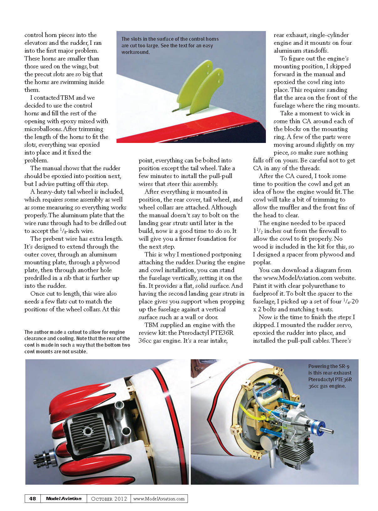
When it was time to epoxy the control horn pieces into the elevators and the rudder, I ran into the first major problem. These horns are smaller than those used on the wings, but the precut slots are so big that the horns were swimming inside them.
I contacted TBM and we decided to use the control horns and fill the rest of the opening with epoxy mixed with microballoons. After trimming the length of the horns to fit the slots, everything was epoxied into place and the problem was fixed.
The manual shows that the rudder should be epoxied into position next, but I advise postponing this step.
A heavy-duty tail wheel is included, which requires some assembly as well as some measuring so everything works properly. The aluminum plate that the wire runs through had to be drilled out to accept the 1/8-inch wire.
The prebent wire has extra length. It's designed to extend through the outer cover, through an aluminum mounting plate, through a plywood plate, then through another hole predrilled in a rib that is further up into the rudder.
Once cut to length, this wire also needs a few flats cut to match the positions of the wheel collars. At this point, everything can be bolted into position except the tail wheel. Take a few minutes to install the pull-pull wires that steer this assembly.
After everything is mounted in position, the rear cover, tail wheel, and wheel collars are attached. Although the manual doesn't say to bolt on the landing gear struts until later in the build, now is a good time to do so. It will give you a firmer foundation for the next step.
This is why I mentioned postponing attaching the rudder. During the engine and cowl installation you can stand the fuselage vertically, setting it on the fin. It provides a flat, solid surface. And having the second landing gear strut in place gives you support when propping up the fuselage against a vertical surface such as a wall or door.
TBM supplied an engine with the review kit: the Pterodactyl PTE36R 36cc gas engine. It's a rear-intake, rear-exhaust, single-cylinder engine and it mounts on four aluminum standoffs.
To figure out the engine's mounting position, I skipped forward in the manual and epoxied the cowl ring into place. This requires sanding flat the area on the front of the fuselage where the ring mounts.
Take a moment to wick in some thin CA around each of the blocks on the mounting ring. A few of the parts were moving around slightly on my piece, so make sure nothing falls off on yours. Be careful not to get CA in any of the threads.
After the CA cured, I took some time to position the cowl and get an idea of how the engine would fit. The cowl will take a bit of trimming to allow the muffler and the front fins of the head to clear.
The engine needed to be spaced 1 1/2 inches out from the firewall to allow the cowl to fit properly. No wood is included in the kit for this, so I designed a spacer from plywood and poplar.
You can download a diagram from the Model Aviation website. Paint it with clear polyurethane to fuelproof it. To bolt the spacer to the fuselage, I picked up a set of four 1/4-20 x 2 bolts and matching T-nuts.
Now is the time to finish the steps I skipped. I mounted the rudder servo, epoxied the rudder into place, and installed the pull-pull cables. Nothing was wrong with the way these cables are installed, but I had a hard time getting them right, especially the cables coming forward from the tail wheel.
I'm not a surgeon, but I imagine trying to thread these cables through the holes and tubes is like arthroscopic surgery. I was using long needle-nose pliers at weird angles, while reaching through the door and windscreen opening.
The rudder servo is mounted back in the passenger compartment, which compounded the issue for me, but I did manage to get it sorted out.
The throttle servo mounts slightly forward of the rudder servo and has to operate a long throttle pushrod. A thin metal pushrod is included in the kit, but in order to keep electronic engine noise to a minimum, I substituted this for a Du-Bro flexible pushrod system.
When I attached the throttle pushrod to the carburetor, I added another pushrod that lets me manually operate the choke through the cowl opening. A simple Z-bend went through the choke lever, and I rigged up a bracket that would support it from the front, held in place by the engine's mounting bolts.
I also substituted one other item: the fuel tank. There's nothing wrong with the supplied tank; it's a standard blow-molded tank. However, I received a RotoFlow fuel tank from J&L Power Products and this looked to be the perfect time to try it out.
The RotoFlow comes preassembled and the clunk rotates around a central pickup line. All I had to do was hook up the fuel and vent lines, and then strap it in position with the tie wraps that came in the SR-9 kit.
The vent line wraps around the tank. This is a tip I picked up in some of my work with gas-powered IMAC airplanes. The vent line on a gas engine is not pressurized and vents to the outside. Fuel can leak out of the vent if the airplane is in certain positions such as a vertical downline.
To keep this from happening, the vent line is wrapped along the side, the back, and back along the other side to form a loop. It works well and only requires a bit more tubing for a trouble-free tank installation.
Next the landing gear fairings, wheels, and wheel pants are installed. If you attached the landing gear struts first, make sure you put the landing gear fairings on first. They are vacuum-formed pieces and there is a left and right, so pay attention. They must be trimmed and if you cut to the molded-in trim line, the fit is perfect.
You'll have to eyeball a cutout in each fairing to allow the threaded spacers to protrude. These spacers are where the wing struts bolt to the fuselage. Glue the fairings in position and then attach the wheels.
When it came time to attach the wheels, another problem occurred: there was no included hardware that was correct for mounting the wheels. The wheels have a 6mm diameter hole, yet the instructions called for a 5mm bolt to make up the axle. None was included.
The remaining bolts were 3mm, which are too thin and too short. I picked up a set of 1/4-20 x 2 1/4 hex bolts and matching nuts that worked. They are slightly larger in diameter than the 6mm size, so the wheels and the landing gear holes had to be drilled larger.
There are no predrilled holes in the wheel pants, so you'll have to eyeball that as well. There are provisions for a smaller screw to be installed above the axle bolt that will stop the wheel pants from turning or spinning around the axle.
With the SR-9 on its feet, I set about installing the radio. There's plenty of room in the fuselage to mount nearly any brand and size of radio you choose. Extensions have to be run back to the left and right elevator servos, as well as up to the wing roots for the flap and aileron servos on each side. To hold these in place I picked up a set of Wire Keeps. These small, die-cut foam pieces have adhesive strips on the back and make installations neater. They also keep the extensions to the wing root in place and out of sight.
I installed a Smart-Fly remote ignition cutoff. Quest makes these cutoffs and they allow you to cut the ignition from your transmitter using a spare channel. It utilizes a fiber-optic system so the ignition is opto-isolated from the receiver.
The receiver, dual batteries, and the Smart-Fly system are held in place with hook-and-loop. I glued in a couple of squares of 1/16-inch balsa sheet to go under the receiver and batteries, giving the hook-and-loop material a surface area on which to mount.
I included a plywood plate inside the port cabin door that is not part of the kit. I despise mounting switches on the surface of the fuselage of any scale airplane and make every attempt to hide them. With such a large fuselage and two functional doors, it seemed like the perfect place to hide both the receiver power and ignition power switches. I did a bit of measuring and made this plate from some scrap light plywood. In hindsight, I should have also put the aluminum fuel dot on the plate as well.
I originally set up the radio with a master/slave combination for both aileron servos, both elevator servos, and both flap servos. After extensive experimenting with my 9503 radio, I found that the elevator servos weren't matching in throw and speed. They weren't off too much, but it was enough that it would have induced a bit of roll, making trimming the SR-9 impossible. No amount of transmitter programming could entirely fix the problem and I found that the flaps were worse. The 9503 had no midpoint flap adjustment so both servos were way out of sync. To solve this, I bought a couple of reversing Y-harnesses and installed them, which solved the elevator and flap problems.
When the radio was in place, I finished the fuselage by installing the windows, windscreen, and the cabin doors. With the exception of the windscreen, all the windows are glued in place. The windscreen is held in place with a number of smaller screws.
Several of the screws that are installed above the tank area only thread into a thin layer of balsa. Even wicking a bit of thin CA will not give enough material for the screws to firmly hold. I cut a few 3/4-inch squares from some 1/8-inch light plywood. After I drilled the holes for the windscreen, I could then feel where these squares should be applied. I used medium CA to hold them in position. I redrilled the holes to extend through the plywood so the screws tightened nicely.
The instructions say to epoxy the door hinges into place on the door and the fuselage. If the hinges were epoxied, the doors would only open roughly 60°. I decided not to epoxy the hinges to the fuselage, but to hold each hinge in place with a single screw (the same type that holds the windscreen in position). This will allow me to completely remove the doors if a problem arises.
One last issue popped up during the final assembly. The wing struts are held in place with two screws: one for the top, and one for the bottom. The bottom screw threads into the spacer that extends from the landing gear fairings, but there were no screws included that were short enough to allow me to tighten the strut firmly. I had to source those screws as well. They need to be roughly 1/4-inch to 3/8-inch long.
The assembly was finally finished. Several problems were overcome; however, when it's finished, it really looks great.
It's hard to determine the exact assembly time, but I'd estimate 15 to 20 hours. I spent a couple hours each night for two weeks, but not all of it was actual building. Some was waiting for epoxy to cure.
There was a good surprise: the CG was spot-on, even with the twin receiver batteries. The weight came in at 19 1/4 pounds, ready to fly.
One last note before the flying portion: have you ever put together a project such as a piece of furniture and have a few screws and other hardware left over? Our review SR-9 kit takes this to another level. After double-checking to make sure I didn't miss any steps, I found myself with a tidy pile of hardware: a handful of screws, nuts and bolts, a few dozen washers of various sizes, T-nuts, flat hinges, two sizes of point hinges, and even an extra threaded spacer.
These all can be used in future projects, but it seems as though someone at the factory scooped up a few handfuls of miscellaneous hardware and put it in the kit. Maybe this helps make up for the hardware that wasn't included.
You'll probably need spares of the smaller screws and washers that secure the stabilizer halves and the wing struts. Have extras so you won't ruin a day's flying because of a missing screw.
Engine First Run
Before the first flight, I took the time to start the break-in procedure on the Pterodactyl PTE36R 36cc. A fuel-to-oil mixture between 20:1 and 40:1 is called for, so I used a 30:1 mixture I had on hand. The break-in propeller is not specified in the manual, but TBM's website suggests an 18x8 propeller and lists the break-in time at about 5 gallons of fuel.
With everything in place, it was time to start flipping. It took roughly 25 to 30 flips to get the first ignition burp when choked, then another 10 or so to bring the engine to life. I ran the first tankful at 25% throttle with no adjustments to the carburetor to lubricate everything.
During the next run I adjusted the carburetor so the top end was approximately 7,800 rpm and idle was roughly 2,400 rpm. Satisfied with this as a starting point, it was time to put on the cowl and see how the SR-9 flew.
Flying
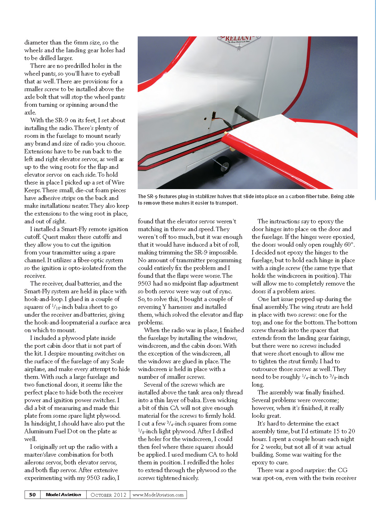
It takes roughly 10 to 15 minutes at the field to bolt the wings and stabilizer into place, attach the wing struts, and top off the tank. The plug-in wings and stabilizer halves are easy to install and have a good, firm fit. The stabilizer halves are held in place with a couple of screws.
The wings are secured by reaching into the fuselage through the cabin doors and threading a 6mm screw into each wing root. You'll probably want to assemble it on a table to avoid crawling under the wings.
Firing the PTE36R for the first flight, I found that the idle was too high for proper taxiing, but because the cowl was already on and I knew that I could kill the engine at any time with the Smart-Fly ignition cutoff, I went with it as is.
The SR-9 took off in roughly 100 feet and had a good climb rate at only three-fourths throttle. After making a few passes for trim, I was fighting the model because it was way too sensitive, especially in pitch (elevator). Most of the early turns looked like those a pylon racer would make. Any touch of the elevator equated to big changes in altitude.
The manual calls out a throw of 40mm each way (a touch over 1 1/2 inches). The rudder was similarly touchy, so I set up for a few practice approaches. With the idle set as high as it was, the Stinson would not land, even with flaps, so I climbed to a safe altitude, cut the throttle, and glided in for an uneventful landing.
It was time for reprogramming. I cut the elevator and rudder throw considerably (to about 1 inch). I also added exponential: 60% on the elevator and 45% on the rudder. I left the ailerons alone.
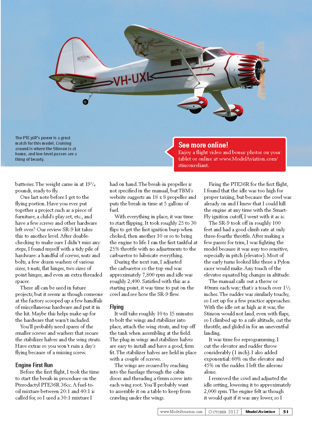
I removed the cowl and adjusted the idle setting, lowering it to approximately 2,000 rpm. The engine felt as though it would quit if it was any lower, so I kept it there. The PTE36R ran very smoothly and the SR-9 was much easier to fly. I was able to perform nice, scale-like turns and the model was much less twitchy. With the expo and reduced throw, the SR-9 was delightful. The flaps worked well and made for shorter landing approaches. Crosswind landings were manageable. The model cruises well at around half throttle and loafs along at 3/4 throttle. I used about 30% of the 32-ounce tank on a typical flight. The PTE36R's power is a great match for this model. Cruising around is where the Stinson is at home, and low-level passes are a thing of beauty.
I bolted everything together and it was on to flight two. Although not quite perfect, the flight was much more scale-like and I was able to get a better feel for the model. You might think it would fly like a giant trainer, but it requires some attention, especially in the turns where you'll have to coordinate the ailerons and rudder.
The full-scale Stinson is not an aerobatic design, but this model will do modest loops, stall turns, and barrel rolls, and will spin easily with that big rudder. Cruising around is where the Stinson shines, and low-level passes are beautiful.
The 9503 has a three-position switch for flaps, and I had the most fun at full flaps. At this setting the flaps were deployed close to 60° and they slow the SR-9 to a crawl. With the ample power of the PTE36R, there's plenty of propeller blast over the control surfaces.
Landings are easier and slower using flaps. I found it better to land with a steeper approach, a little more power, and then flare right at roughly 2 feet off the runway. It will settle, and normally you can land without too much bouncing. The gear and hard foam tires don't have much give, so it is very easy to bounce a landing on pavement, but the Stinson lands well on grass.
Conclusion
TBM's Stinson SR-9 is a beautiful airplane and faithful to its full-scale counterpart. It's a big model with a 100-inch wingspan, but this size makes it easy to work on and in. There are some problems along the way, but it's nothing that an intermediate or experienced modeler can't overcome, and I described how to dodge these problems in the review.
In the air, the SR-9 looks the part. Resist the urge to fly it at full throttle, and please don't shoehorn a 50cc (or larger) engine in the cowl. It doesn't need it. The PTE36 is plenty of power and if you fly the SR-9 as intended you'll rarely need anything over half throttle.
—Tom Sullivan tmsullivan@roadrunner.com
Manufacturer / Distributor
Troy Built Models (941) 342-8685 www.troybuiltmodels.com
Sources
- Horizon Hobby — (800) 338-4639 — www.horizonhobby.com
- Smart-Fly — (480) 460-2652 — www.smart-fly.com
- ElectroDynamics — (734) 422-5420 — www.electrodynam.com
- J&L Power Products — (262) 628-3506 — www.jlproducts.net
- Du-Bro Products — (800) 848-9411 — http://hobby.dubro.com
- Dean & James LLC — www.wire-keeps.com
- Maxx Products — (847) 438-2233 — www.maxxprod.com
- Stinson Reliant history — www.edcoatescollection.com/ac1/austu/VH-UXL.html
- Grubby Fingers Aircraft Illustrations — www.grubby-fingers-aircraft-illustration.com/stinson.html
Transcribed from original scans by AI. Minor OCR errors may remain.

