

REVOLT!
By Bob Kopski
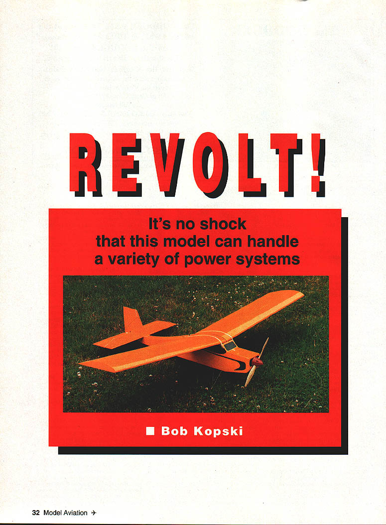
It's no shock that this model can handle a variety of power systems.
The REVOLT! originated in 1992 as a model that could be used to easily test-fly a wide variety of electric products. It is a simple outline, 600-square-inch cabin design with heavy Fifties- and Sixties-influence. It has a 12.5% thick flat-bottom wing section with decades of known good flyability. It employs proven incidence, moment-arm, and tail-surface-area proportions.
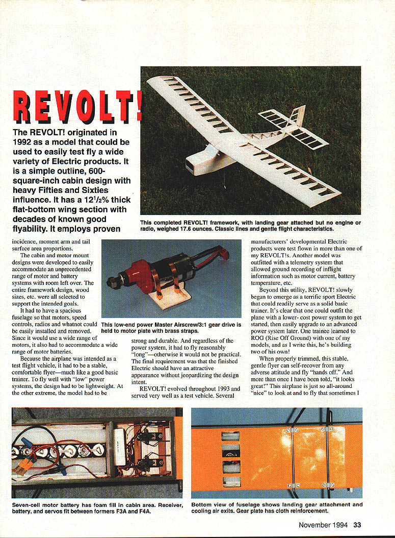
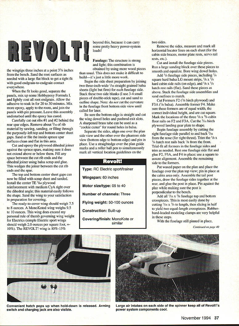
The cabin and motor-mount designs were developed to easily accommodate an unprecedented range of motor and battery systems, with room left over. The entire framework design and wood sizes were selected to support these goals. The fuselage had to be spacious so motors, speed controls, radios and the like could be easily installed and removed. Since it would use a wide range of motors, it also had to accommodate various motor batteries.
Because the airplane was intended as a test-flight vehicle, it had to be a stable, comfortable flyer—much like a good basic trainer. To fly well with "low" power systems the design had to be lightweight; at the other extreme the model had to be strong and durable. And, regardless of the power system, it had to fly reasonably long—otherwise it would not be practical. The final requirement was that the finished electric should have an attractive appearance without jeopardizing the design intent.
REVOLT! evolved throughout 1993 and served very well as a test vehicle. Several manufacturers' developmental electric products were test-flown in more than one of my REVOLT!s. Another model was outfitted with a telemetry system that allowed ground recording of inflight information such as motor current and battery temperature.
Beyond this utility, REVOLT! slowly began to emerge as a terrific sport electric that could readily serve as a solid basic trainer. You can outfit the plane with a lower-cost power system to get started, then easily upgrade to an advanced power system later. One trainee learned to ROG (rise off ground) with one of my models, and as I write this he's building two of his own!
When properly trimmed this stable, gentle flyer can self-recover from any adverse attitude and fly "hands off." And more than once I have been told, "It looks great!" This airplane is just so all-around nice to look at and to fly that sometimes you forget its original purpose.
For routine flying at the lower-power end, REVOLT! works well with Master Airscrew and geared cobalt .05 motors on seven 1.4 Ah SCR or 1.7 Ah SCRC cells. (I've even used two 7-cell packs in parallel to extend flight time.) At the higher-power end I've used direct and geared 25s and 40s on 14 and 18 cells respectively for spirited flight. Of course, anything in between—such as direct and geared cobalt 15s and the Graupner Turbo 700—also flies REVOLT! very nicely. REVOLT! has been flown at weights ranging from 52 to 94 ounces.
Typical REVOLT! flight times range from a solid 6–8 minutes with lower-power, lower-cell-count systems up to 14–16 minutes for the bigger systems flown the same way. Such flights include taxi, takeoff, climb out, loops, touch-and-gos, cruising, and other simple maneuvers consistent with a three-channel model.
As with any electric, the best flying is usually accomplished using a speed control for efficient use of battery resources—to apply full power when needed and reduced levels when not.
A word before construction begins: The plans shown are the latest version. However, some photos were taken during REVOLT! design evolution and may show minor structural details that differ from the present plans. The plan takes precedence, while the photos offer good overall guidance.
CONSTRUCTION
Stab and rudder
I like to begin a new model by building the tail surfaces first—they are simple and result in a quick sense of accomplishment. Assembly of these surfaces is mostly straightforward, with only a few special points to be made:
- Choose wood appropriate for the purpose. Leading and trailing edges and ribs should be medium-firm and straight.
- Use light sheet for the stab center section, elevator and rudder—no need for "strong and heavy" here.
- The elevator can be hinged with almost any plastic hinges, or with plastic tape as illustrated. The rudder uses pin-type plastic hinges.
- A long hinge pin of .020 music wire replaces the short pins that come with commercial hinges; this simplifies assembly and disassembly.
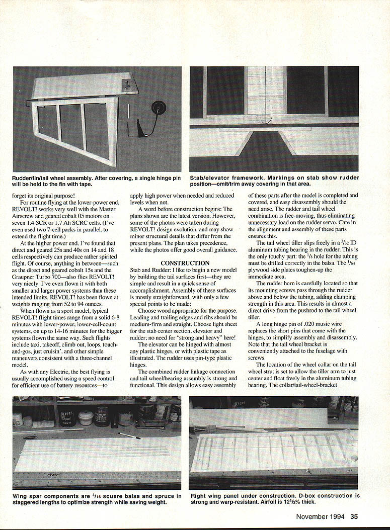
- The rudder uses a combined rudder-linkage connection and tail-wheel-bearing assembly that is strong and functional. This design allows easy assembly after covering and easy disassembly if needed. The rudder and tail-wheel combination is free-moving, eliminating unnecessary load on the rudder servo—care in alignment ensures this.
The tail-wheel tiller slips freely in a 7/32" ID aluminum tubing bearing in the rudder. This is the touchy part: the 1/8" hole for the tubing must be drilled correctly in the balsa. The 1/16" plywood side plates toughen the immediate area.
The rudder horn is located so that its mounting screw grabs through the rudder above and below the tubing, adding clamping strength and resulting in an almost direct drive from the pushrod to the tail-wheel tiller. The location of the wheel collar on the tail-wheel strut is set to allow the tiller arm to just center and float freely in the aluminum tubing bearing. Check the collar, tail-wheel bracket, and the spruce and balsa pieces to verify accuracy. If everything looks good, separate the pieces and reassemble using medium-thick cyanoacrylate (CyA) glue: apply accelerator to one wood side, adhesive to the mating (unaccelerated) side, then press and hold the pieces against a straightedge.
Wings
Begin wing construction after spar assemblies are prepared. Use medium-firm wood for ribs, light A-grain for planking and capstrips, and firmer sheet for the trailing-edge pieces. The leading-edge (LE) strip should be cut with the top edge beveled 38 degrees as shown on the plans. If beveling is difficult, make the rectangular LE stock 1/16" higher than shown and butt the top LE planking against its inside edge at the appropriate assembly step.
- Precut all 1/16" sheet LE and TE planking to proper width but a bit longer than the plan dimension. The LE top and bottom planking stop at mid-spar to allow rib capstrips to rest on the spar. The top planking sheet width is greater than the bottom width due to airfoil curvature.
- Begin assembly by laying the LE and TE bottom sheet in place over the plan, allowing a bit of overhang at the centerline. Mark rib locations on the sheet with a fine-point roller-ball pen (careful not to ding the wood).
- Glue the LE strip and the 1/8" square TE capstrip in place.
- Install the center section sheet, stopping it 3/16"–1/4" behind the spar rear edge; this gap will be filled later. All sheeting should extend slightly beyond the wing centerline for later trimming.
- Mist the LE and TE sheeting at the marked rib locations with accelerator. Set a bottom spar in place (spruce end toward the root), allow it to overhang the centerline, and temporarily set several ribs to align it. Glue ribs to the LE, planking, capstrips, and TE sheet by running thin CyA over the interfaces. Install remaining ribs.
- Note that the root rib is placed at a 6° slant inward—do this accurately using the pattern provided. Run thin CyA at the spar/planking interface to secure the spar to the bottom planking.
- Cut and install shear webs—do not omit this important step. Trial-fit the top spar, then remove it, spray accelerator on the inside (bottom) surface, apply medium-thick CyA in the rib notches and on the web tops, and press the spar in place with the spruce end overhanging the centerline slightly.
- Trial-fit the top LE planking, remove and spray accelerator on the inside. Apply medium-thick CyA to the LE strip, top spar surface, and the rib top edges between the LE and spar, then carefully place the top sheeting (accelerator side down) and press, pin, or weight it into place. Glue TE sheet pieces similarly.
- Install the top capstrips and center sheeting, stopping the latter 3/16"–1/4" behind the spar edge. Assemble the other wing half the same way—be sure to build one left and one right panel.
- Carve and sand the LE to shape, sand both panels to finished quality, and pay special attention to sanding the root spar and sheet overhang flush with the angled root ribs.
- Trial-fit the dihedral joint by propping up the panels and checking alignment. Glue the dihedral joint with medium-thick CyA. When dry, reinforce and finish the joint as shown on the plans and sand to final shape.
Place the four completed spar assemblies on the bench and run a sanding block over them, rotating the spars to get all sides and edges.
Specifications
- Type: RC electric sport/trainer
- Wingspan: 60 inches
- Motor size/type: .05 to .40
- Number of channels: Three
- Flying weight: 50–100 ounces
- Construction: Built-up
- Covering/finish: MonoKote or similar
Fuselage
The structure is strong and light; this is achieved by using more wood pieces than usual. This does not make it difficult to build—just a bit more work.
- Begin side-sheet preparation by joining two 3"-wide 1/16" straight-grained balsa sheets (light but firm) for each fuselage side. Stack these blanks (3–4 small pieces of double-stick tape), cut and sand to the outline shape. Do not cut the curvature in the fuselage front bottom side view until called for later.
- Be sure the bottom edge is straight. Cut wing-dowel holes and pushrod exit slots. A sharpened brass tube can be used as a cookie-cutter for round holes in balsa.
- Separate the sides and align one over the plan side view and the other over the phantom side view (bottom edge to bottom edge), pin in place, and use a straightedge on the plan guide marks to simultaneously mark vertical location guidelines on both sides. Remove the sides and mark horizontal locator lines for cabin side braces, motor-plate rests, servo-rail rests, etc.
- Cut and install fuselage-side pieces. Run a large sanding block over these pieces to smooth and equalize. Bore wing-dowel holes. Add 1/4" fuselage-side pieces, including 1/4" square hard-balsa landing-gear-mount strips, 1/8" x 1/4" hard cabin side rails (on edge), and 1/8" x 1/4" hatch rest rails (flat). Sand these pieces as above. Stack the fuselage-side assemblies and sand outlines to match.
- Cut formers F2 (1/8" birch plywood) and F3A (1/8" balsa). Assemble former F4. Make sure formers are equal width, correct height, and cut square. Mark locations of the three 1/8" x 3/8" cabin floor rails on F2 and F3A. Cut the 1/8" plywood landing-gear plate to shape.
Begin fuselage assembly:
- Cut the right fuselage side parallel to and back 3/16" from the nose for right thrust. Trim hatch rests back 1/8" from the front.
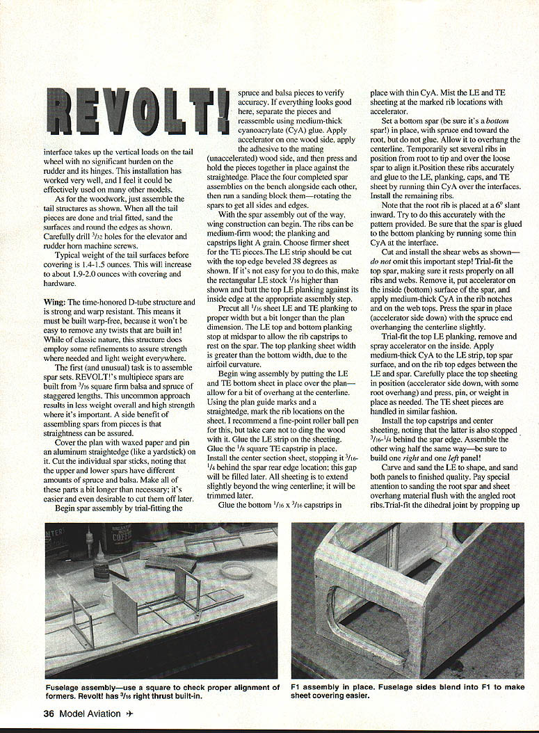
- Trial-fit all formers in the fuselage sides and trim as needed. Rest one fuselage side flat and glue F2, F3A, and F4 in place; use a square to assure alignment. Assemble the remaining side to the formers.
- Put waxed paper on the plan and place the fuselage over the top view; pin in place at the cabin area only. Assemble the tail-post pieces, draw the fuselage sides together at the rear, glue the post in place, and pin against the plan while making sure the post is perpendicular to the bench.
- Add all 1/16" x 3/8" fuselage top and bottom crosspieces. This is most easily done by cutting 1/16" x 3/4" to length and slicing in half. Rubber-band-loaded modeling clamps are helpful.
- Sand top edges from F4 to the stab LE location to make them smooth and equal. Glue the 1/16" x 1/2" plywood crosspiece at F4; add 1/16" sheet aft of this and the 1/16" sheet at the stab LE. Add the 1/16" x 1/4" top longeron and crosspiece capstrips.
- Install the 1/8" x 3/4" crosspiece at the base of the windshield and the 1/8" sheet tapered-width crosspiece at the top nose location. Sand across all top edges as required. Add the 1/8" x 1/2" triangle-section crosspiece at the stab LE location. Remove the assembly from the board.
- Complete the fuselage bottom assembly by installing 1/8" x 3/8" hard-balsa battery-bearer strips between F2 and F3A. Sand these flush with the fuselage bottom edges and glue the 1/16" birch plywood landing-gear mount plate in place. Add the bottom-surface 1/16" balsa sheet crossgrain from this plate back past F4 as shown and allow for air exits.
- Cut to fit and install the 1/8" bottom-sheet fill between the longerons at the rear. Install 1/16" hard sheet over this area as shown. Install the bottom 1/16" x 1/4" longeron and crosspiece capstrips. Trim and sand overall as required.
- Assemble the motor-bearer frame over the plan; remove, sand, fit, and glue in place. Add the three hard 3/8" triangular-stock pieces underneath the bearer frame as shown. Sand front fuselage edges flat in preparation for the front former. Cut away the temporary 1/8" x 1/4" rear motor-plate balsa crosspiece.
- Assemble F1 from four alternating-grain hard 1/16" sheets. Two thicknesses fit inside the fuselage opening and two cover the full front. Make inside ones to fit, glue to oversize outside ones, then trim the outside pieces to size. Cut the front opening in this F1 stack and glue in place.
- Using a plan tracing as a guide, mark, cut, and sand the left and right-side bottom-nose curvature. Sand the bottom of F1 smooth to this curvature. Add the 1/16" crossgrain bottom sheeting from the plywood gear plate forward, following the forward curvature past F1. This is most easily done by applying accelerator to the sheet and medium-thin CyA to the fuselage pieces. Trim, sand, and blend into F1.
- Cut, fit, and install top cabin LE and TE balsa wing-saddle crosspieces, F3B, and the 1/16" windshield sheet. Assemble hatch pieces from light A-grain 1/8" sheet and 1/64" plywood and install the hold-down. Cut and fit the wing dowels and remove temporarily.
- Sand the fuselage thoroughly. The fuselage should weigh about 6.0–6.5 ounces ready to cover, and 6.5–7.0 ounces when covered with MonoKote.
Assemble the landing gear, fit it to the fuselage, then remove. Assemble tailwheel bearing and strut, temporarily install as shown, and remove. Mark and drill final holes with a 1/16" bit before inserting the #2 x 3/8" sheet-metal screws. When the screws are removed, put a drop of thin CyA in the holes to toughen the threads. Don't reinstall the screws before the glue has cured.
RC equipment installation
- Cut servo rails to size and glue them in place as required for your servos.
- Make and install pushrods of your choice.
- Temporarily install rudder and elevator horns and trial-fit the tail surfaces using pins to hold. Make and trial-fit all linkages, then remove hardware and tail surfaces.
- Install receiver, battery and wiring harness behind F3A. I use double-stick Velcro to mount the receiver and battery to the floor or to the former—coat the wood with Ambroid first, let dry, then attach Velcro.
Power system installation
- Cut a 1/8" lite-ply motor-mount plate to the width needed for your motor. It should slip in place between the fuselage sides and on the bearers. Mark mounting-hole locations and drill with a 1/16" bit. Position the plate on the bearers and, using the plate as a guide, drill into the bearers and triangular-stock with a long 1/16" bit.
- Remove the plate and enlarge the existing holes with a 3/32" bit for clearance. Do not redrill the bearer holes. Trial-fit the plate and temporarily insert #2 x 3/8" sheet-metal screws in the bearer holes to verify fit. When the screws are removed, put a drop of thin CyA in the holes to toughen the threads—do not reinstall screws before the glue has cured.
- Mark the thrustline on the plate using the plan as a guide. Allow for the intended thrust and for the prop shaft to emerge centered in the nose opening.
- Cut any needed spacer pieces (and the thrust-balance block) to form the motor-nesting V-block. Allow for 1/16" foam motor-rest tape.
- Cut and form motor tie-down straps from .016" x 1/4" brass strip. The square pull-down tubes are 7/8" I.D. brass. Mark and drill motor tie-down screw holes in the motor-mount plate and glue 2-56 blind nuts on the plate bottom.
- Trial-fit motor and tie-downs to the plate using 2-56 x 3/4" socket-head draw screws. Install this assembly in the model, verifying thrustline, prop center, and overall clearances.
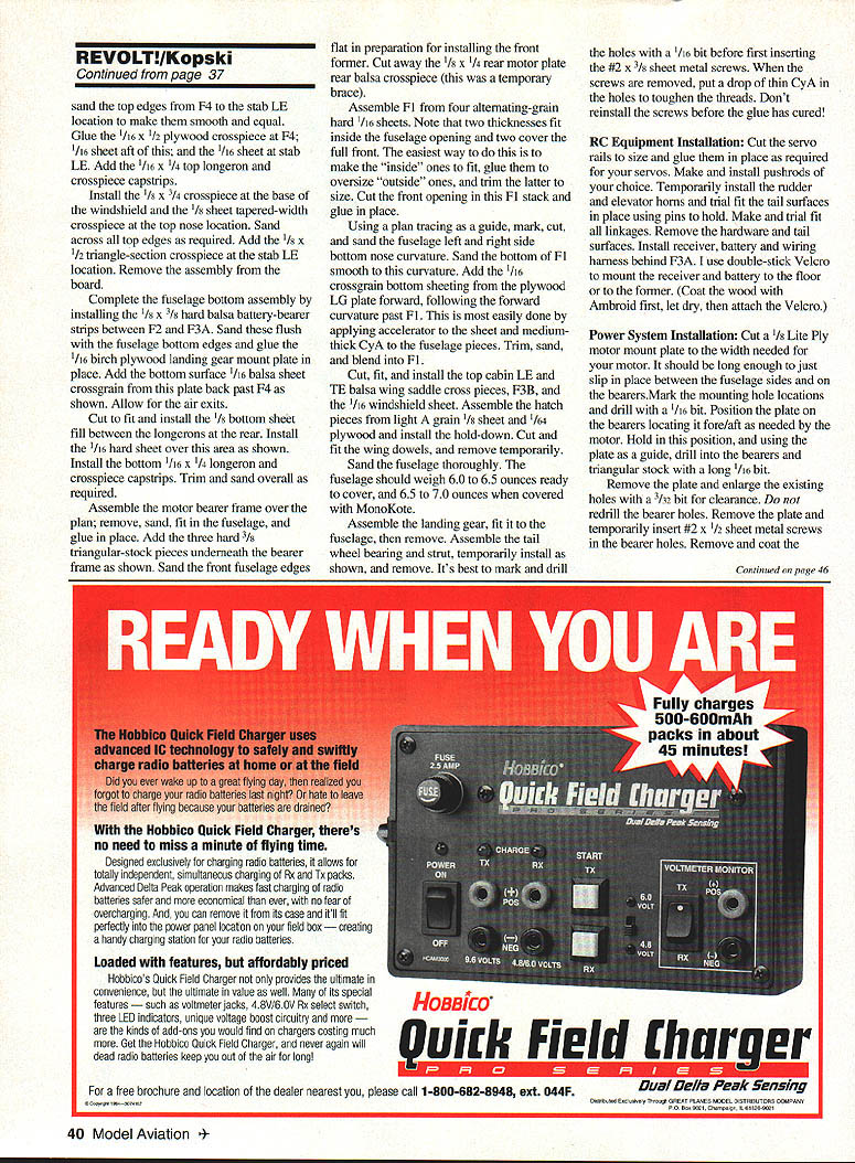
- Install the motor battery using a snug-fitting plastic-foam block to fill excess space; the foam prevents escape of cooling air and keeps the pack in place. Incoming cooling air is intended to flow from the cowl intersections for battery cooling.
- Install the speed control where shown with double-stick Velcro. Install wiring harness/arming switch/charge connector assembly as required. Interconnect the speed control and receiver, then charge and test the motor system.
Covering
- Remove heavier equipment and surface-mounted hardware in preparation for covering.
- Install iron-on cloth reinforcement over the landing-gear plate. Use a household iron with a paper towel between it and the cloth and follow the manufacturer's heat recommendations. Bondo/Men-O-Fix tape (available at sewing departments) works well for this—it's easy, inexpensive, and strong.
- I cover my REVOLT!s with MonoKote, but any lightweight covering will do. Recover the individual tail surfaces first, assemble the fin to the stab, then attach the entire tail assembly to the covered fuselage. Leave covering off where glue joints will be made.
- After covering, reinstall all equipment. Verify balance and shift the motor battery as needed to stay within the indicated range. Some larger power systems may require added weight at the rear of the fuselage. Check all equipment and control-surface directions and throws.
At this point you're done. There is nothing more to say except: go fly a REVOLT! And here's hoping you enjoy this electric as much as I have!
— Kopski
Transcribed from original scans by AI. Minor OCR errors may remain.

