

RF Sniffer
If a transmitter has been left on, the sniffer's tone will let you know.
People often comment that things were simpler in the "good old days." This is certainly true of our modern RC transmitters. Not too many years ago, our transmitters used AM (Amplitude Modulation) and did not provide the bells and whistles we now take for granted. Most new radio systems now use FM (Frequency Modulation) and offer many features, including systems called FM, PCM, and PPM. While not as simple as the older systems, they are much better.
A number of years ago a circuit was published for an RF sniffer (by George Steiner, I believe) that was basically a diode detector with its output applied to a Radio Shack audio amplifier. When this combination was placed near an operating RC transmitter, the speaker would emit a loud buzz — the detected AM modulation. I made several of these sniffers, and my club used them for many years in our club transmitter impound. They served us well.
My club sponsors the KRC Electric Fly. This is a major event for electric-powered model aircraft enthusiasts, and in 1996 we had almost 300 transmitters in the impound area. We used two sniffers: one on the incoming table and one to sweep the transmitter racks and tables periodically to be sure no switches were accidentally bumped on during handling.
In recent years we saw the increase in FM and PCM radio systems and noticed our old sniffers did not detect these new systems very well. We had to almost touch the new transmitters with the sniffer antenna, and even then the speaker buzz was barely audible. The old sniffer was designed to detect AM modulation, and there was no AM modulation to detect.
I decided it was time for a new RF sniffer design — one that would detect a transmitter with any type of modulation equally well, and take us into the 21st century. I call it the RF Sniffer 2100.
Circuit description
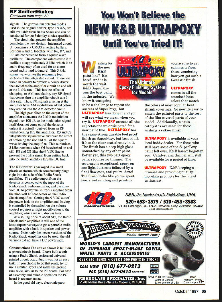
- Q1 and associated components (R1, R2, R4, R5, C1, C4) form a broadband RF amplifier with approximately 10 dB of gain.
- The amplifier output is coupled into a biased Schottky-diode AM detector through a high-pass RF filter comprised of C3, L1, and C5.
- The combination of the RF amplifier and high-pass filter provides an RF front end with amplification from below 20 MHz to above 100 MHz.
- Resistor R9 supplies a trickle of DC bias current through detector diodes D1 and D2 to increase sensitivity to low-level RF signals. (Germanium detector diodes used in the original sniffer, type 1N34A, are still available and can be substituted for the Schottky diodes specified.)
Integrated circuit U1 contains six CMOS inverting buffers. Sections 1 and 2, together with R6, R7, and C7, form a square-wave oscillator at approximately 3 kHz — an attention-getting alarm frequency. The 3 kHz square wave drives the remaining four sections of U1 wired in parallel to provide a power driver that switches the amplifier circuit on and off at a 3 kHz rate.
This switching chops any RF that comes through the amplifier at 3 kHz, effectively adding AM modulation to FM signals before they reach the AM detector. The high-pass filter on the amplifier output attenuates the 3 kHz modulation signal by over 100 dB so the modulation itself does not appear at the detector output unless it is derived from an actual RF signal coming through the amplifier. R3 and C2 integrate the square wave to soften the rise and fall and minimize 3 kHz transients. R8 and C8 filter the 9 V DC line to keep the 3 kHz signal from getting back into the audio amplifier through the DC line.
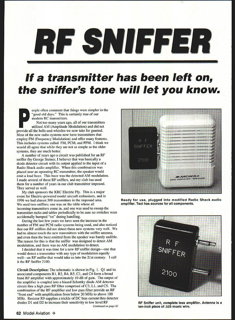
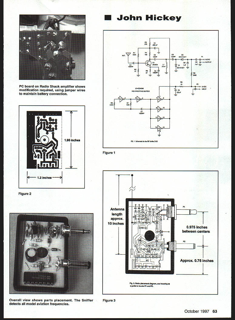
The RF Sniffer is packaged in a small plastic enclosure and plugs into the side of the Radio Shack audio amplifier. The detector's audio output is connected to the input of the Radio Shack amplifier, and the sniffer is powered from the amplifier's 9 V DC connector. A short modification to the Radio Shack amplifier is required so the 9 VDC is switched with the amplifier's volume control; this is discussed later.
At a selling price of about $12, the Radio Shack audio amplifier is still one of the least expensive ways to get a portable audio amplifier with a built-in speaker and power source. Note: only the newer versions of the Radio Shack amplifier can be used; older versions did not have a DC power jack.
Construction
- The unit is built on a printed circuit board. A Radio Shack perforated universal PCB can be used, but it is more difficult; use a layout with wide ground runs similar to the printed board. The provided PC board is easier for reliable operation.
- Parts are available from local electronics stores or mail-order houses such as Digi‑Key. Many suppliers have minimum orders or sell in multiples.
- A local company supplies etched-and-drilled PC boards or a complete kit of parts. Built and tested units are also available. The kit includes parts only for the RF Sniffer, not the Radio Shack amplifier. For source and ordering details, contact John Hickey, 1624 Maple Ave., Hatfield, PA 19440 (send a SASE for parts list with Digi‑Key and Radio Shack part numbers).
Assembly recommendations (refer to the parts-placement diagram shown in Fig. 3 while assembling):
- Mount all resistors first.
- Install the two jumper wires near U1 (use discarded resistor leads as jumpers).
- Install capacitors C1 through C9, observing correct polarity for electrolytics (C8). Install C9 vertically: one lead down into the PC board (soldered), the other standing vertically for later soldering to the center pin of P1.
- Install D1 and D2, Q1, and U1. Orient parts as shown and remember the banded end of D1 and D2 is the cathode.
The Radio Shack housing (cat. no. 270-288) is held together with a single screw on the back side. Modifications to the housing:
- Screw the housing together tightly and wrap several layers of tape lengthwise to hold the halves securely while drilling holes for P1 and P2.
- Drill a 15/64-inch diameter hole 0.75 inch up from the bottom right-hand corner on the center seam at the side of the housing (for one connector).
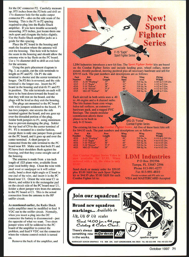
- For the DC connector P2 and audio output connector P1: carefully measure and drill an 11/32-inch hole for P1 and place it .975 inch from the P2 hole (this spacing lets the sniffer plug into the Radio Shack amplifier). If accurate measurement is difficult, locate the holes about 1 inch apart and elongate slightly. Use the amplifier jacks as a guide.
- Mark and drill a 1/32-inch exit hole below the seam for the antenna so the wire lays flush on the PC board.
Mounting P1 and P2:
- Cut the side terminals to length: on P1 the side terminal is shorter and the center terminal is longer; on P2 this is reversed.
- Trial-fit P1 and P2 with the PC board; bend side terminals down so they rest on the board and the plugs exit the housing level.
- Mount the plugs to the PC board using wire jumpers soldered to the board. P1 uses two jumpers (one secures the side terminal; one goes over the threaded portion). Solder the top lead of C9 to the center terminal of P1.
- P2 is mounted with one jumper from ground on the PC board that goes up and over the center terminal; a short jumper connects the side terminal to the PC board near R9.
- Make sure both P1 and P2 are flush against the housing and exit straight.
Antenna:
- Use a ten-inch length of 0.025" piano wire. Clean with steel wool or sandpaper, bend a short right-angle or Z-bend at one end, and insert it in the PC board near U1 oriented near C1.
- Solder the wire to the rectangular pad on the circuit side and solder a short jumper from the antenna to the PC board at C1 (this is the actual connection to the RF sniffer circuit).
Radio Shack amplifier modification:
- By default, inserting a plug into the amplifier's DC connector disconnects the internal battery. To have the amplifier feed 9 VDC out to the sniffer (and have it switched by the volume control), two short jumper wires must be soldered to the amplifier's PC board to correct the wiring.
Checkout
- Feed the antenna through the housing, insert the PC board assembly into the housing, plug the sniffer into the side of the audio amplifier, and turn the amplifier volume all the way up.
- A low-level 3 kHz tone should be audible at the speaker. In normal operation the volume only needs to be about one-third rotation, and the 3 kHz tone is not noticeable. (The volume control adjusts audio level only; it does not affect RF sniffer sensitivity.)
- Turn on an RC transmitter with its antenna down and bring it near the RF sniffer. When the transmitter is within about 24–36 inches, a noticeable 3 kHz tone should appear. At 6 inches the tone will be very loud. With the transmitter antenna extended, detection typically reaches 15–20 feet. If the transmitter uses AM modulation you will also hear a raspy buzz along with the 3 kHz tone.
- If the sniffer does not work, turn it off and recheck the circuit-side of the PC board for unsoldered joints and shorts. Verify parts placement and component orientation.
- After everything checks out, remove the sniffer from the amplifier. Verify the housing cover closes correctly, remove the cover, and while holding the PC board in the housing carefully apply five-minute epoxy around P1 and P2 to secure them to the PC board and lock them into the housing. Do not allow epoxy to get into the housing seal perimeter.
- To prevent eye injury, bend a small loop in the end of the antenna or glue a small plastic bead to the antenna end (craft-store beads or a push-pin bead work).
Application and tips
- The RF Sniffer is not intended to be a scanner or sensitive receiver. It will detect nearby RC channels — including 27 MHz CB, 50 MHz RC ham frequencies, and 72/75 MHz RC channels — when you are close to the transmission source. The sniffer is intentionally insensitive so it does not pick up all the transmitters operating on the flightline (those transmitters are supposed to be on).
- To reduce sensitivity: shorten the sniffer antenna to about 6–8 inches, or omit the bias on the detector diodes supplied by R9 (cut one lead of R9 and leave the other end connected to the PC board). To restore sensitivity, resolder the R9 lead.
- Current drain from the amplifier battery is only about 10 mA. With a typical 400 mAh nine-volt alkaline battery, the sniffer will operate for almost 40 hours on one battery.
- Other uses: testing your own transmitters with the antenna up and down to get a baseline for normal operation; verifying a transmitter is putting out normal power (this does not substitute for a full-range check). Although optimized for 20–100 MHz, it will detect most transmitters if you get close enough — cordless phones, garage door openers, cell phones, and even the microwave oven (with Schottky diodes).
Happy sniffing! John Hickey 1624 Maple Ave. Hatfield, PA 19440
Parts list for the RF Sniffer 2100
Semiconductors
- D1, D2 — SD101ACT Schottky barrier rectifier
- Q1 — 2N3904 NPN transistor
- U1 — CD4049UBE hex inverting buffer CMOS integrated circuit
Resistors
- (All resistors are 1/4 watt, 5% carbon)
Transcribed from original scans by AI. Minor OCR errors may remain.

