
Ridiculous
What would you call a model which so totally flies in the face of tradition in both concept and size? It may not be the ultimate Stunter, but it is the closest approach to that pinnacle yet obtained. The design evolved over several years of testing. Except for some as-yet unconfirmed airfoil discoveries, most of the aerodynamic design owes its inception to Bill Netzeband, with whom I have worked closely for years.
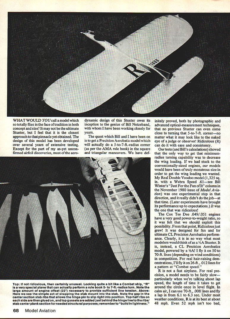
Bill and I set out to get a Precision Aerobatic model that will actually do a 5- to 7-ft.-radius corner (as per the AMA rule book) in the square and triangular maneuvers. We have proved, by photographic and optical-measurement techniques, that no previous Stunter can even come close to turning that 5- to 7-ft. corner. Ridiculous (R) can do it with ease and consistency.
Our tests and Bill's calculations showed the only way to get that minimum-radius turning capability was to decrease the wing loading. Using conventionally sized engines would have required a truly monstrous model to obtain the wing loading we wanted. The Cox Tee Dee .049/.051 engines, with their very good power-to-weight ratio, allowed us to exploit that possibility. From there, Ridiculous just grew. It was designed for fun and for ultimate CL Precision Aerobatics performance. It is not what most modelers would think of as a 1/2A Stunter; it is a CL Precision Aerobatics model powered by a 1/2A.
Performance and handling
- I fly R on 50- to 70-ft. lines depending on wind conditions in competition. For hair-raising demonstrations I’ll fly it on 26-ft., .012 lines for a pattern at "Combat" speed.
- R is not a fast airplane. For real precision, a model needs to be fairly slow, particularly regarding lap speed (the time to circle once in level flight).
- In calm air with 70-ft., .008 lines you can lap in about 6.1–6.3 seconds.
- R performs best at roughly 48 mph; 52 mph is acceptable, but short lines force the engine to work hard.
- Note the large amount of engine offset—about 22°—necessary to provide sufficient line tension for the sharp turning ability.
- The negative aspect of R’s light wing loading and sharp-turning ability is that it can bob around in turbulent air—typical of very lightweight ships on long lines.
Engine, prop and fuel recommendations
For the flier who just wants to build R and have fun (and possibly win some Stunt contests), I recommend:
- Stock Cox .049/.051 engine with slight modifications:
- Needle valve modified for infinite adjustment
- Bored-out venturi
- Fuel: 15% nitro
- Prop: Cox black nylon 5x3
- Expected in-flight rpm: about 22,200–23,500 rpm
- Expected airspeed: roughly 46–52 mph
- You can check engine rpm using the technique in the "Musical Tach" article (Model Aviation, January 1981).
To keep the small engine running steadily through maneuvers you’ll need a very good fuel-supply system: I use a pressure bladder system with two bladders, a fuel filter, and a fuel shutoff for maximum consistency. Line tension can be quite light; very precise elevator control is needed. Use a very large bellcrank to give plenty of muscle to handle surface air loads and a custom-fitted, fingers-only control handle. I'll describe these fully later.
Construction
R is essentially a highly modified Combat design minus structural deadwood. Because weight is critical, build as lightly and efficiently as possible. Soft to medium balsa is acceptable.
Stabilizer
- Build the stabilizer first. It’s probably the most difficult part and must be lightweight. Covered and ready to install on the monoboom, the stabilizer plus mounting stub should weigh no more than 1/4 oz.
- Cut the stabilizer plank from 1/8 x 4-in. soft-to-medium balsa. The center section uses the full 1/8-in. thickness for strength around the hinge pocket. The outer areas are reduced in thickness by sanding; the pattern of recess areas on the plans is for medium-weight wood. Softer balsa should have smaller recesses.
- Glue a 3/32-in. brass tube bushing to the front of the plank and reinforce with a wrap of nylon fabric.
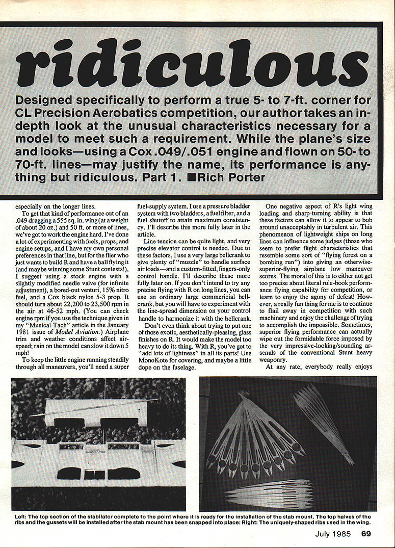
- Ribs are built from upper-half and lower-half pieces: generally 1/32-in. balsa, except for a few 1/16-in. ribs adjacent to the hinge bushings. Glue ribs to each side of the plank and sand to final shape.
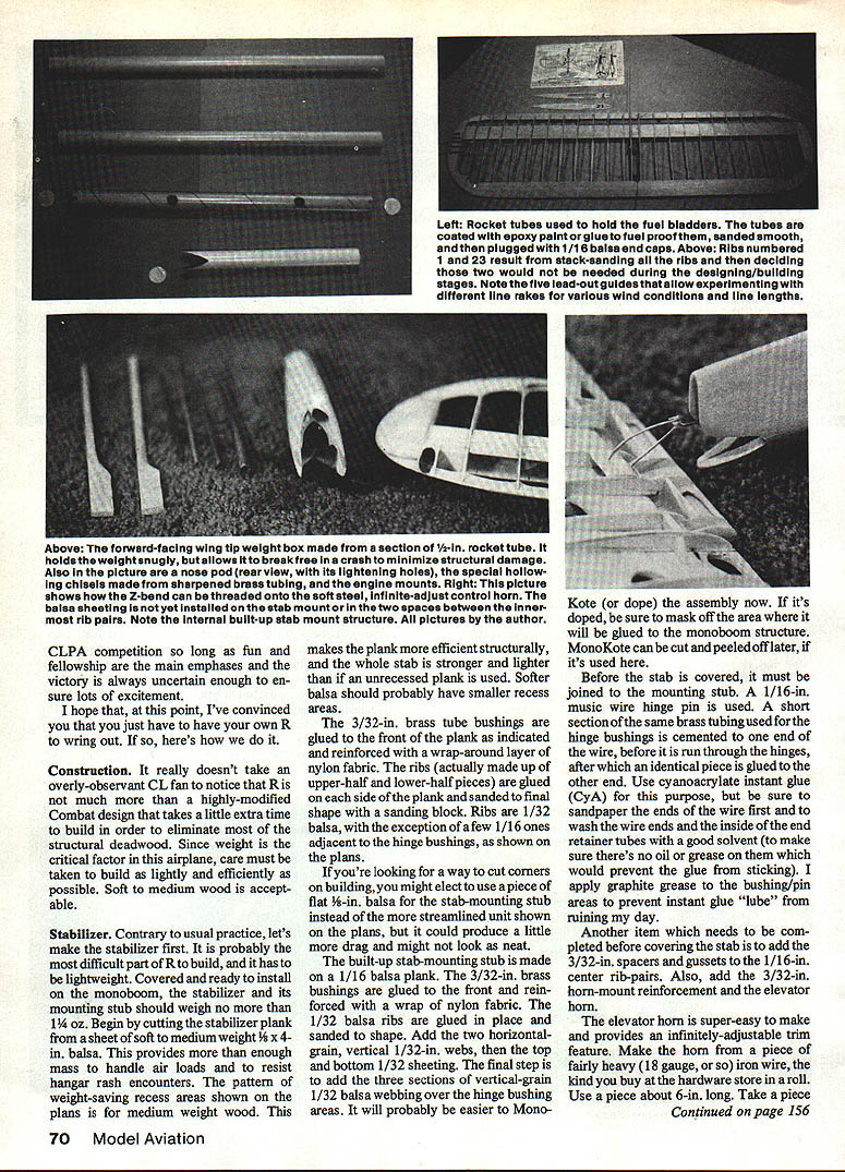
- The built-up stab-mounting stub is made on a 1/16-in. balsa plank. Glue the 3/32-in. brass bushings front and rear and reinforce with nylon fabric. Add two horizontal-grain 1/32-in. webs, then top and bottom 1/32-in. sheeting. Finally add three sections of vertical-grain 1/32-in. webbing over the hinge bushing areas.
- Covering: MonoKote is recommended; a light dope finish on the fuselage is optional. If doped, mask the area that will be glued to the monoboom. Expect some warping when ironing covering—shrink from the tips toward the center and iron out warps as you go.
- Hinge pin: Use 1/16-in. music wire. Cement a short section of the same brass tubing used for the hinge bushings to each end of the wire (use CA). Sand and solvent-wash the wire ends and inside the tubes beforehand. Apply graphite grease to the bushing/pin areas to prevent CA from seizing the hinge.
- Add 3/32-in. spacers and gussets to the 1/16-in. center rib pairs and add the 3/32-in. horn-mount reinforcement and the elevator horn.
Elevator horn (adjustable, bushed)
- Make the horn from a piece of fairly heavy (about 18-gauge) iron wire, roughly 6 in. long.
- Take a 2-in. piece of 1/16-in. music wire, insert it into a 1/2-in. length of small-diameter plastic fuel line. Wrap a turn of the iron wire around this assembly, compressing the loop so the plastic is squeezed around the music wire. Trim the iron wire ends to about 1 3/4 in.
- Remove the music wire from the plastic tube, add a few drops of CA to the tubing/iron-wire connection, cut off excess plastic tube, and finish shaping the horn with needle-nose pliers.
- Epoxy the horn in place on the stab; sand the wire where it is glued to improve adhesion. This horn system is robust—pushrod or stab will fail before the horn bends.
Wing
- The center-spar system was used to develop an airfoil with minimum skin-friction drag. To minimize warps and irregularities, stack-sand the ribs with stub spars in the rib slots and number every rib in the order it came out of the stack. Reinstall ribs in the same relative order.
- Ribs are 1/16-in. sheet balsa per plans, except the center rib is 1/8-in. Make circular cutouts for the rocket tube only in the center ribs and only after stack-sanding.
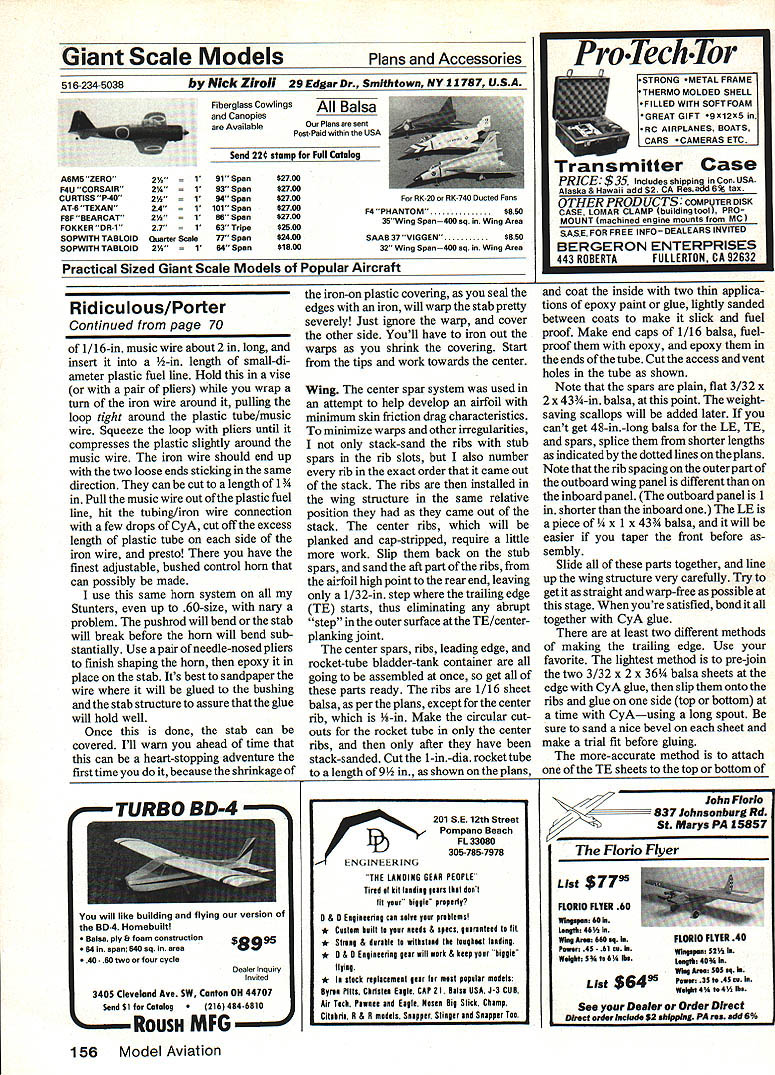
- Rocket tube: use a 1-in.-diameter tube cut to 9-1/2 in. Coat the inside with two thin applications of epoxy paint or glue (lightly sand between coats) to make it slick and fuelproof. Make 1/16-in. balsa end caps, fuelproof them with epoxy, and epoxy them into the tube. Cut access and vent holes as shown on the plans.
- Spars: plain, flat 3/32 x 3/32 x 43-1/4 in. balsa initially; weight-saving scallops added later. If you can't get 48-in. balsa for the LE, TE, and spars, splice shorter lengths as indicated on the plans. Note rib spacing differences between outboard and inboard panels. LE is 1/4 x 1 x 43 balsa—taper the front before assembling.
- Assemble center spars, ribs, leading edge, and rocket-tube/bladder-tank container at once. Line up and bond with CyA glue.
- Trailing edge: two methods. Lightest: pre-join two 3/32 x 2 x 36 balsa sheets at LE and TE with CyA, then slip them onto the ribs and glue to spars. Alternative: attach one TE sheet at a time with CyA using a long spout. Sand bevels and trial-fit before gluing.
- If you must add servos or hardware in the center section, do it before final planking and capstripping. Keep everything as light as possible.
- Add 1/16-in. balsa planking and 1/16 x 1/2-in. cap strips. Round the leading edge to a blunt curve in the planked area.
Control system, bellcrank and fuel lines
- Before planking the center section, ensure the control system is tight and friction-free in every line-rake mode. Steam out any warps that have developed; do not wait until after planking.
- Use a large bellcrank to handle light line tension and fine elevator control. A custom-fitted fingers-only control handle is recommended for ultimate precision.
- I use 25- to 50-lb.-test nylon string for lead-outs. At the lead-out guides use sections of the outer tubing of Sullivan Gold-N-Rod (red tube) material. Provide five of them to allow lead-outs to be strung through various combinations to change line rake—vital when experimenting with different line lengths and wind conditions.
- To reduce friction and wear, encase portions of the lead-out in the inner rod sections of Gold-N-Rod material. Add a parallel length of lead-out string as "strain relief" where the lead-out emerges from the tube. Affix tube to lead-out and strain relief with CA glue and microballoons at each end.
- Make the lead-out rod long enough to protect the entire length of lead-out that contacts the guide sheath. Press a 1/8-in. slice of silicone fuel line on the outboard tapered end of each inner rod to prevent it from falling through the lead-out guide and into the wing; these are removable for line-rake changes.
- Use inner rod material on bellcrank/engine shutoff kicker contact points and as an exit guide for the fuel shutoff pushrod to the engine. Glue a section of outer sheath to the fuel shutoff wire to provide an oil-deflecting slip joint that keeps engine oil out.
Bellcrank suspension
- The plans show a bellcrank-support suspension system I recommend. It is rugged and prevents bellcrank pullout. The suspension uses the same 25- to 50-lb.-test nylon string as the lead-outs.
- Put the string in place before any planking is attached. Press dimples into ribs where the string crosses and glue the string in place. After planking, glue the string along the inner edge of the planking.
- If you prefer, omit the string suspension and use a 1/4-in. center rib reinforced with 1/16-in. plywood.
Adding lightness and finishing
- After planking and cap strips are dry, mark areas to remove with a soft pencil and carve and sand LEs, spars, and TE to final contours.
- Thin the TE to approximately 1/16 in. after warps are steamed out.
- Concentrate structural mass in the center and taper toward wing tips, stab, stab tips, and engine mount. This strategy approximates required strength at critical points and maximizes probability of structural survival in a vertical dive into the ground.
- Cover the wing with iron-on plastic film. Chrome MonoKote on top helps prevent warp from sunlight.
- Avoid heavy finishes (glass, lots of dope); they add unacceptable weight. Use MonoKote and, if needed, a little dope on the fuselage.
Wing tip weight (tip "box")
- Make the outboard wing tip weight box from a length of 1/2-in.-dia. rocket tube. Carve a 1/8-in. balsa plug for the aft end and epoxy the tube in place in the wing tip. Shape the front of the tube to match the aft airfoil section.
- Use a pointed lead weight wrapped in sponge rubber to fit snugly in the tube. Cover the open end with transparent tape until you have the final trimmed weight needed, then patch with MonoKote.
- The advantage: in a crash the tip weight can push through the tape/covering and not break structure by being rigidly glued in place.
Sources of rocket tubes
- Hobby shops that carry model rocketry supplies may stock separate rocket tubes. Otherwise you’ll need to buy model rocket kits.
- By mail: Flight Systems, Inc., 9300 E. 68th St., Raytown, MO 64133 (crush-resistant tubes, bond-paper finish; $1 for a catalog) or Estes Industries, Penrose, CO 81240 (thin, lightweight glassine-finished tubes; free catalog).
To be continued.
Transcribed from original scans by AI. Minor OCR errors may remain.

