
Ridiculous - Part 2
Body parts and tail boom
Construction of the rest of the airplane is straightforward.
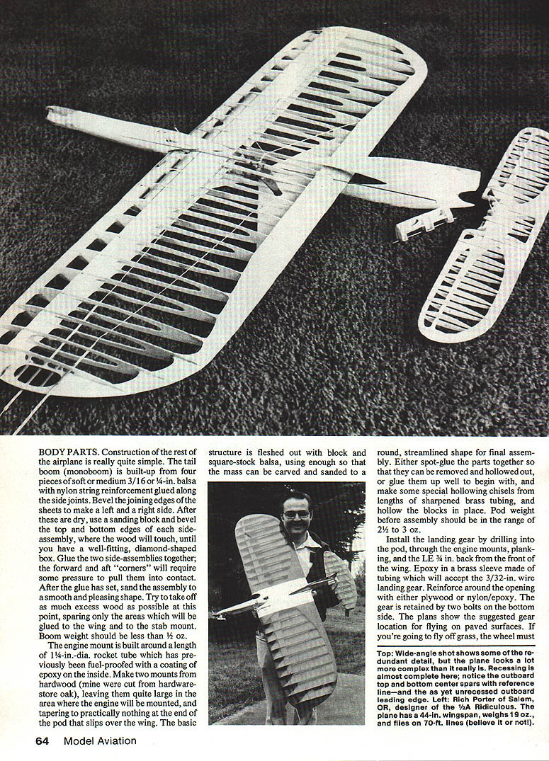
- Tail boom (monoboom): Build up from four pieces of soft or medium 3/16" or 1/4" balsa with nylon-string reinforcement glued along the side joints. Bevel the joining edges of the sheets to make a left and a right side. After these are dry, use a sanding block to bevel the top and bottom edges of each side assembly where the wood will touch, until you have a well-fitting diamond-shaped box. Glue the two side assemblies together; the forward and aft "corners" will require some pressure to pull them into contact. After the glue has set, sand the assembly to a smooth, pleasing shape. Remove as much excess wood as possible, sparing only the areas that will be glued to the wing and to the stab mount. Boom weight should be less than 1/2 oz.
Engine pod and mount
- Engine mount: Built around a length of 1-1/4" dia. rocket tube that has been fuel-proofed with an epoxy coating on the inside. Make two hardwood mounts (oak works well), leaving them large where the engine will be mounted and tapering to nearly nothing where the pod slips over the wing. Flesh out the basic structure with block and square-stock balsa so the mass can be carved and sanded to a round, streamlined shape.
- Either spot-glue parts so they can be removed and hollowed out, or glue them up and hollow them in place using sharpened brass-tube chisels. Pod weight before assembly should be 2–3 oz.
- Engine location and CG: Do not mount the engine until everything else is completed; its location is determined by where you want the center of gravity (CG).
- For calm-weather flying on 50 ft. lines with the gray 5-3 prop, position the engine so the model's CG is 0.15 in. ahead of the wing quarter-chord (the quarter-chord is 3 in. back from the front of the wing).
- For windy weather or longer-line flying (black 5-3 prop and longer lines), the CG should be about 0.2–0.5 in. ahead of the quarter-chord. Nose ballast (fuel in the front tank or lead) may be needed to move the CG up to ~0.7 in. ahead for very windy conditions.
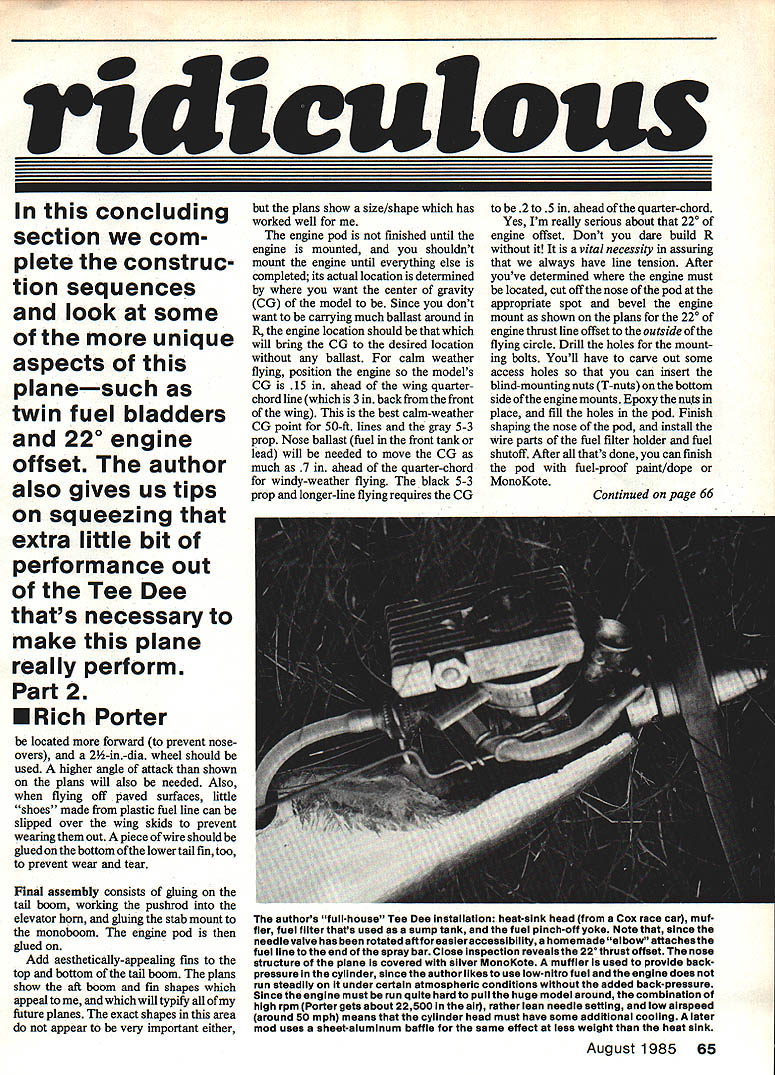
- Engine thrust line offset: A 22° engine offset to the outside of the flying circle is essential to maintain line tension. After determining engine position, cut off the nose of the pod, bevel the engine-mount opening for the 22° offset as shown on the plans, and drill the mounting-bolt holes. Carve access holes to insert blind mounting nuts (T-nuts) on the bottom side of the engine mounts; epoxy the nuts in place and fill the holes. Finish shaping the nose, install the wire parts of the fuel-filter holder and the fuel shutoff, then finish the pod with fuel-proof paint/dope or MonoKote.
Landing gear
- Install the landing gear by drilling into the pod through the engine mounts, planking and the LE about 3/16" back from the front of the wing. Epoxy in a brass sleeve (tubing) to accept 3/32" wire landing gear. Reinforce the opening with plywood or nylon/epoxy. The gear is retained by two bolts on the bottom side.
- For paved surfaces, the plans show the suggested gear location. If flying off grass use a 2" dia. wheel and the higher angle-of-attack shown on the plans. For paved surfaces, slip little shoes made from plastic fuel line over the wing skids to prevent wear. Glue a piece of wire to the bottom of the lower tail fin to prevent wear and tear.
Final assembly
Final assembly consists of:
- Gluing the tail boom in place.
- Fitting and working the pushrod and elevator horn.
- Gluing the stab mount to the monoboom.
- Gluing on the engine pod.
Add aesthetically appealing fins to the top and bottom of the tail boom; the plans show aft-boom fin shapes that have worked well. The exact shapes in this area appear important.
For engine installation, either the author's full-house Tee Dee installation, or a heat-sink-head Cox race-car muffler and fuel filter used as a sump, will work well.
Fuel tanks and plumbing
- Nose tank: Made the same size as the wing tank, then folded to about half-length (more or less) depending on desired forward ballast capacity. Retain the folded position with rubber bands. Pre-season the nose bladder by over-inflating with air a couple of times before installation so it provides slightly less fuel pressure than the wing tank.
- Wing tank: Mount as shown on the plans.
- Bladder trick: Make a bladder from surgical tubing (about 6 in.). Tie a slipknot at one end, pull tight, and rubber-band the fuel line into the other end. Center a 1" piece of brass or aluminum tubing with a 90° bend inside the bladder, stuff it into the end and wrap a No. 18 rubber band tightly around the elbow.
- Silicone fuel line to brass tube: Wrap one turn of small-diameter copper wire around the brass tube about 1/8" from the end and solder it in place. Sand lightly to provide a lip that helps keep the fuel line on.
Fuel shutoff
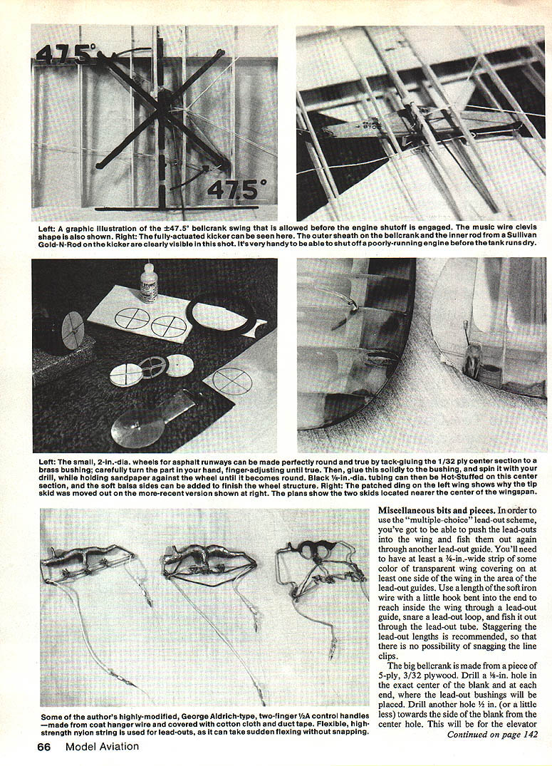
The fuel shutoff is simple: a wire holder glued on top of the pod holds the fuel line in a fixed saddle. A piece of soft iron wire bent to pinch the fuel line is glued to a straight section of music wire that is fed back to the bellcrank area. This "kicker" is arranged so the bellcrank moves it about 3/8" to pinch off the fuel line completely. Everything is arranged so the shutoff kicker wire is not moved until the bellcrank is rotated ±47.5° from neutral.
This requires a full swing of the bellcrank; the extra movement to operate the shutoff makes little aerodynamic difference when used at the top or bottom of an outside loop if you use a bit of excess control movement. With the handle/bellcrank geometry used here, that extra movement is not obtained by normal arm/wrist motion—you must intentionally increase the control line spacing at the handle using your free hand to spread the lines farther apart. With practice this is easy and provides the useful ability to kill the engine during flight, preventing overruns or allowing quick shutoff if the engine is set too rich or too lean.
My preference for 1/4A fuel tanks is twin 1-oz. bladders mounted forward to prevent nose-overs.
Bellcrank and controls
- Bellcrank: Make from a piece of 5-ply, 3/32" plywood. Drill a 1/8" hole in the exact center and at each end for the lead-out bushings. Drill another hole about 1/8" toward the side from the center hole for the elevator pushrod bushing.
- Center bearing: Cut a 1/2" piece of 5/8" dia. brass tubing and epoxy it into the center hole, ensuring it is perpendicular to the bellcrank.
- Nylon bushings: Carve three plugs of nylon (1/8" dia., about 1" long). Insert into the plywood holes and mold the ends over each side with a hot soldering iron. Then drill a 1/16" hole through each plug.
- Pivot and centering: Use 3/32" music wire for the bellcrank pivot. Two short (~3/8") lengths of 3/8" brass tubing are used on each side of the bellcrank bearing to center the bellcrank in the wing. These outer tubes are glued into the center rib and to the nylon-string suspension system.
- Elevator pushrod: Made from 1/16" music wire with Z-bends on each end.
- Clevises: Two music-wire clevises are installed in the bellcrank end holes; tie the nylon-string lead-outs to them. Bend the clevises as shown on the plans. Small pins on each end of the bellcrank keep the clevises from swinging around on the back side.
Miscellaneous bits and pieces
- Multiple-choice lead-out scheme: To use it you must be able to push the lead-outs into the wing and fish them out through another lead-out guide. Have at least a 3/4" wide strip of transparent wing covering on one side of the wing in the lead-out-guide area. Use a length of soft iron wire with a small hook to reach inside the wing through a lead-out guide, snare a lead-out loop, and fish it out through the lead-out. Stagger lead-out lengths to avoid snagging line clips.
- Small additions: For paved-surfaces flying, slip plastic fuel-line shoes over wing skids; glue a small wire to the bottom of the lower tail fin to prevent wear.
Engine tuning and fuel
- Ideal engine run: A slightly rich two-cycle in flat, fast flight with only a very slight slowing in overhead maneuvers and a slight richening in violent corners. Needle setting on the ground depends on weather.
- Fuel quantity: I usually carry about 50% more fuel than needed for an official flight and kill the engine with the fuel shutoff two laps after the Four-Leaf Clover. Actual fuel requirements depend on engine setup.
- Weather tuning: Very hot/humid days require richer needle settings; very dry/cold days require near-lean settings. Higher-nitro fuels need leaner ground settings than lower-nitro fuels.
- Recommended fuels and plugs: For economy I prefer 5%–15% nitro fuels with Globe plugs. Fuels at 5% or less nitro content require use of a Cox muffler (the adjustable RC-style one) to provide enough back pressure to keep the glow plug hot.
Trimming and flying
- Sport flying: For sport flying, use a grassy field on 25–50 ft. lines with stock Cox glow heads and flexible nylon props. If your helper can hand-launch the model, landing gear may not be necessary.
- Handle movement: It takes more than ±60° of handle movement to get full elevator travel. I use ±60° rather than the usual ±40° to allow low-level "groovy" flight. My handle is a modified George Aldrich-type 4A, two-finger design made from coat-hanger wire, heavily padded with duct tape over cotton cloth.
- Lead-outs: Use some flexible, very-high-strength nylon string for the handle lead-outs. It withstands violent deflection angles associated with true "book-corner" maneuvers without snapping the way cable might.
- Line rake and weights:
- On two Rs (17.75 oz and 21.5 oz) I find 4½° line rake is best under most conditions when flying on 50–55 ft of .012 lines and on 70 ft of .008 lines.
- The heavier airplane flies better at 3° line rake in calm weather; the lighter airplane prefers 5½° rake in winds above 15 mph on .012 lines—the increased drag helps slow the ship in maneuvers and drops level-flight speed by almost 2 mph.
- A line rake of 1½° is useful for 25 ft .012 lines and for 63 ft .008 lines.
- Rudder offset: 4° to 8° to the inside of the flight circle is a good fine-tune range.
- Alignment check: Set the airplane on towel-padded backs of two kitchen chairs and use a square to determine vertical and horizontal room reference lines. Compare airplane reference lines to these. With wing and stab both at 0° incidence when checked from the side, add 1° of engine downthrust (or upthrust if the model is built to fly clockwise). Drill a hole in a long straight piece of balsa, mount it in place of the prop for a good reference line, and adjust the socket.
Closing
I hope you enjoy your Ridiculous Stunter. If there are any questions, drop a line to Rich Porter, 386 Benji Ct. N.W., Salem, OR 97301.
Transcribed from original scans by AI. Minor OCR errors may remain.

