
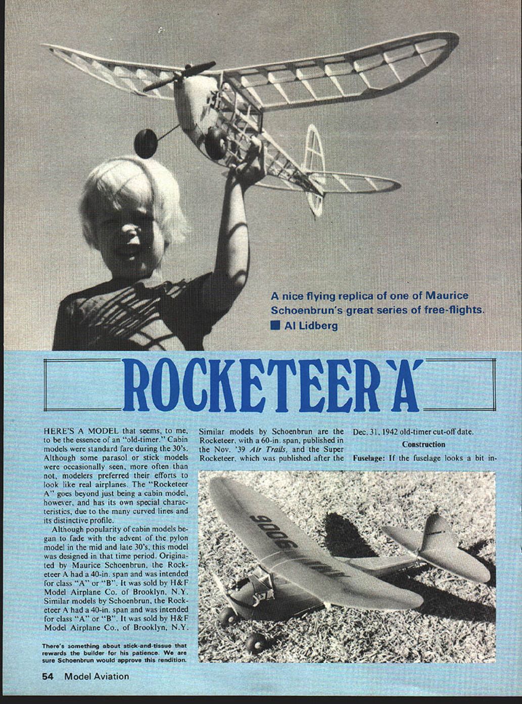
Rocketeer 'A'
HERE'S A MODEL that seems, to me, to be the essence of an "old-timer." Cabin models were standard fare during the 30's. Although some parasol or stick models were occasionally seen, more often than not, modelers preferred their efforts to look like real airplanes. The "Rocketeer A" goes beyond just being a cabin model, however, and has its own special characteristics, due to the many curved lines and its distinctive profile.
Although popularity of cabin models began to fade with the advent of the pylon model in the mid and late 30's, this model was designed in that time period. Originated by Maurice Schoenbrun, the Rocketeer A had a 40-in. span and was intended for class "A" or "B". It was sold by H&F Model Airplane Co., of Brooklyn, N.Y. Similar models by Schoenbrun are the Rocketeer, with a 60-in. span, published in the Nov. '39 Air Trails, and the Super Rocketeer, which was published after the Dec. 31, 1942 old-timer cut-off date.
Construction
Fuselage: If the fuselage looks a bit in-
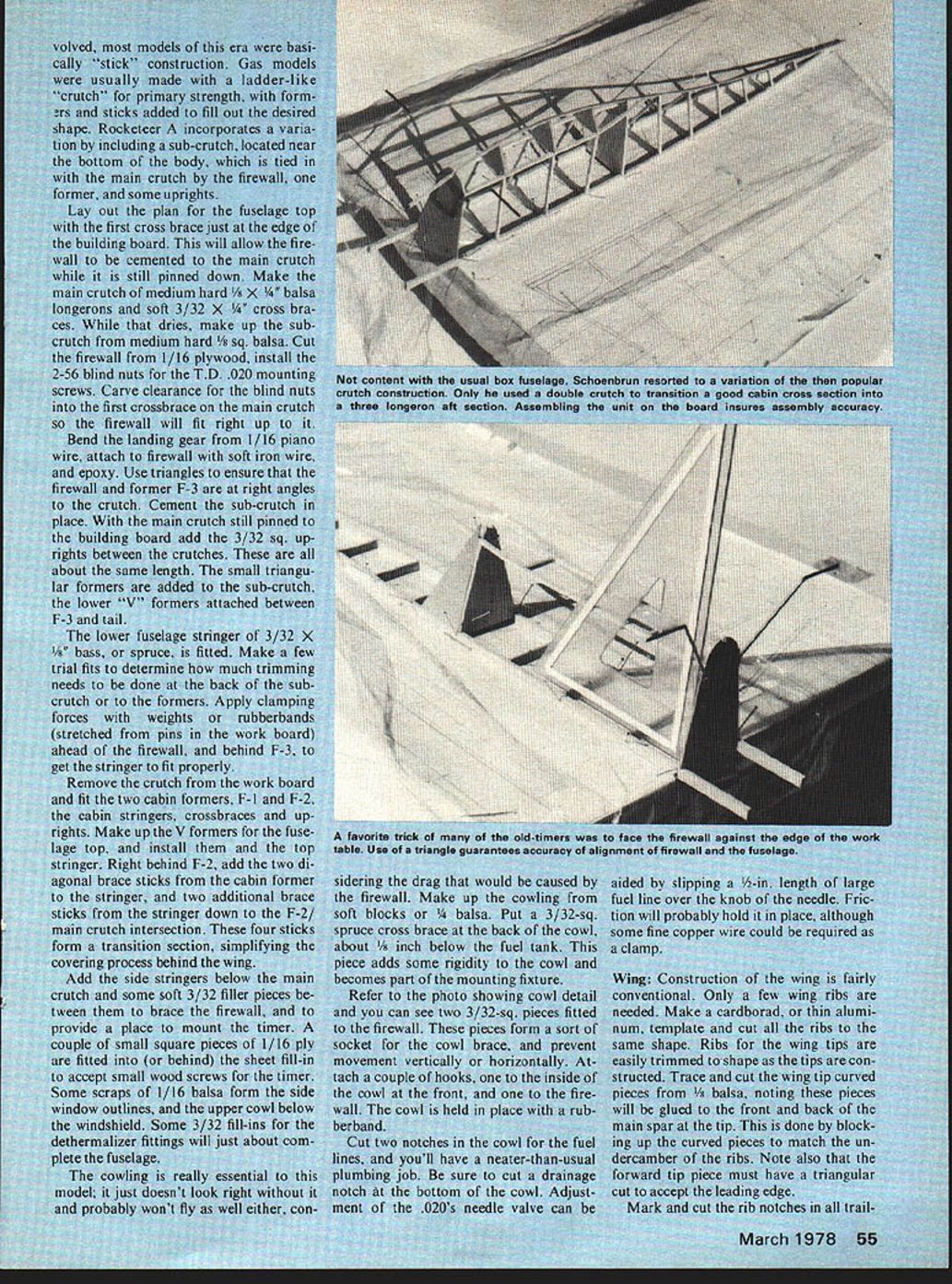
There's something about stick-and-tissue that rewards the builder for his patience. We are sure Schoenbrun would approve this rendition. volved, most models of this era were basically "stick" construction. Gas models were usually made with a ladder-like "crutch" for primary strength, with formers and sticks added to fill out the desired shape. Rocketeer A incorporates a variation by including a sub-crutch, located near the bottom of the body, which is tied in with the main crutch by the firewall, one former, and some uprights.
Lay out the plan for the fuselage top with the first cross brace just at the edge of the building board. This will allow the firewall to be cemented to the main crutch while it is still pinned down. Make the main crutch of medium hard 1/8 x 1/4 balsa longerons and soft 3/32 x 1/4 cross braces. While that dries, make up the sub-crutch from medium hard 1/8 sq. balsa. Cut the firewall from 1/16 plywood, install the 2-56 blind nuts for the T.D. .020 mounting screws. Carve clearance for the blind nuts into the first crossbrace on the main crutch so the firewall will fit right up to it.
Bend the landing gear from 1/16 piano wire, attach to firewall with soft iron wire, and epoxy. Use triangles to ensure that the firewall and former F-3 are at right angles to the crutch. Cement the sub-crutch in place. With the main crutch still pinned to the building board add the 3/32 sq. uprights between the crutches. These are all about the same length. The small triangular formers are added to the sub-crutch, the lower "V" formers attached between F-3 and tail.
The lower fuselage stringer of 3/32 x 1/8 bass, or spruce, is fitted. Make a few trial fits to determine how much trimming needs to be done at the back of the sub-crutch or to the formers. Apply clamping forces with weights or rubberbands (stretched from pins in the work board) ahead of the firewall, and behind F-3, to get the stringer to fit properly.
Remove the crutch from the work board and fit the two cabin formers, F-1 and F-2, the cabin stringers, crossbraces and uprights. Make up the V formers for the fuselage top, and install them and the top stringer. Right behind F-2, add the two diagonal brace sticks from the cabin former to the stringer, and two additional brace sticks from the stringer down to the F-2/main crutch intersection. These four sticks form a transition section, simplifying the covering process behind the wing.
Add the side stringers below the main crutch and some soft 3/32 filler pieces between them to brace the firewall, and to provide a place to mount the timer. A couple of small square pieces of 1/16 ply are fitted into (or behind) the sheet fill-in to accept small wood screws for the timer. Some scraps of 1/16 balsa form the side window outlines, and the upper cowl below the windshield. Some 3/32 fill-ins for the dethermalizer fittings will just about complete the fuselage.
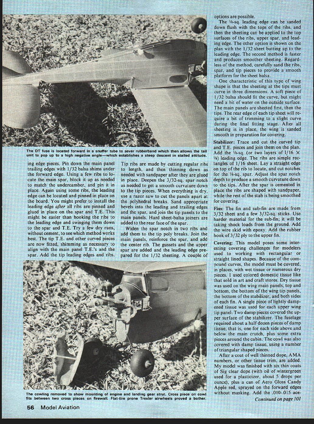
The cowling is really essential to this model; it just doesn't look right without it and probably won't fly as well either, considering the drag that would be caused by the firewall. Make up the cowling from soft blocks or 1/8 balsa. Put a 3/32-sq. spruce cross brace at the back of the cowl, about 1/8 inch below the fuel tank. This piece adds some rigidity to the cowl and becomes part of the mounting fixture.
Refer to the photo showing cowl detail and you can see two 3/32-sq. pieces fitted to the firewall. These pieces form a sort of socket for the cowl brace, and prevent movement vertically or horizontally. Attach a couple of hooks, one to the inside of the cowl at the front, and one to the firewall. The cowl is held in place with a rubberband.
Cut two notches in the cowl for the fuel lines, and you'll have a neater-than-usual plumbing job. Be sure to cut a drainage notch at the bottom of the cowl. Adjustment of the .020's needle valve can be aided by slipping a 1/2-in. length of large fuel line over the knob of the needle. Friction will probably hold it in place, although some fine copper wire could be required as a clamp.
Wing:
Construction of the wing is fairly conventional. Only a few wing ribs are needed. Make a cardboard, or thin aluminum, template and cut all the ribs to the same shape. Ribs for the wing tips are easily trimmed to shape as the tips are constructed. Trace and cut the wing tip curved pieces from 1/8 balsa, noting these pieces will be glued to the front and back of the main spar at the tip. This is done by blocking up the curved pieces to match the undercamber of the ribs. Note also that the forward tip piece must have a triangular cut to accept the leading edge.
Mark and cut the rib notches in all trailing.
Rocketeer 'A'
edge pieces. Pin down the main panel trailing edges with 1/32 balsa shims under the forward edge. Using a few ribs to locate the main spar, block it up as needed to match the undercamber, and pin it in place. Again using some ribs, the leading edge can be located and pinned in place on the board. You might prefer to install the leading edge after all ribs are pinned and glued in place on the spar and T.E. This might be easier than hooking the ribs to the leading edge and swinging them down to the spar and T.E. Try a few dry runs, without cement, to see which method works best. The tip T.E. and other curved pieces are now fitted, shimming as necessary to align with the main panel T.E.'s and the spar. Add the tip leading edges and ribs. Tip ribs are made by cutting regular ribs to length, and then thinning down as needed with sandpaper after they are glued in place. Deepen the 3/32-sq. spar notch as needed to get a smooth curvature down to the tip pieces. When everything is dry, use a razor saw to cut the panels apart at the polyhedral breaks. Sand appropriate bevels into the leading and trailing edges and the spar, and join the tip panels to the main panels. Hard sheet-balsa joiners are added to the rear face of the spar.
Widen the spar notch in two ribs and add them to the tip poly breaks. Join the main panels, reinforce the spar, and add the center rib. The gussets and the upper spar are added and the leading edge prepared for the 1/32 sheeting. A couple of options are possible.
The 1/8-sq. leading edge can be sanded down flush with the tops of the ribs, and then the sheeting can be applied to the top surfaces of the ribs, upper spar, and leading edge. The other option is shown on the plan with the 1/32 sheet butting up to the leading edge. The second method is faster and produces smoother sheeting. Regardless of the method, carefully sand the ribs, spar, and tip pieces to provide a smooth platform for the sheet balsa.
One characteristic of this type of wing shape is that the sheeting at the tips must curve in three dimensions. A soft piece of 1/32 balsa should fit the curve, but might need a bit of water on the outside surface. The main panels are sheeted first, then the tips. The rear edge of each tip sheet will require a bit of trimming to a slight curve during the final fitting stage. After all sheeting is in place, the wing is sanded smooth in preparation for covering.
Stabilizer: Trace and cut the curved tip and T.E. pieces and join them on the plan. Add the 1/8-sq. (or two layers of 1/16 x 1/8) leading edge. The ribs are simple rectangles of 1/16 sheet. Lay a straight edge on top of the rib to locate, and cut notches for the 1/8-sq. spar. Adjust the spar notch depth to produce a smooth curvature down to the tips. After the spar is cemented in place the ribs are shaped with sandpaper, while the rest of the stab is being smoothed for covering.
Fins: The fin and sub-fin are made from 3/32 sheet and a few 3/32-sq. sticks. Use harder material for the sub-fin; it will be taking shock loads from the ground. Add the wire skid with epoxy. Add the rubber hook of 3/32 ply to the upper fin.
Covering: This model poses some interesting covering challenges for modelers used to working with rectangular or straight lined shapes. Because of the compound curves, the model must be covered, in places, with wet tissue or numerous dry pieces. I used colored domestic tissue like that sold in art and craft stores. Dry tissue was used on the wing main panels, top and bottom, the bottom of the wing tip panels, the bottom of the stabilizer, and both sides of each fin. A single piece of lightly dampened tissue was used for each upper wing tip panel. Two damp pieces covered the upper surface of the stabilizer. The fuselage required about a half dozen pieces of damp tissue, that is, one for each side above and below the main crutch, plus some extra pieces around the cabin. The cowl was also covered with damp tissue, using a number of triangular shaped pieces.
After a coat of well thinned dope, AMA numbers, or other tissue trim, are added. My model was finished with six thin coats of Sig clear dope (with oil of wintergreen used for a plasticizer, about 5 drops per ounce), plus a can of Aero Gloss Candy Apple red, sprayed on the forward edges without masking. Add the .010-.015 ace Install the plastic windshield and side windows after doping is completed.
Mount the engine, timer and wheels, and you are nearly ready to fly. Some of the photos show my model with Trexler air wheels. These wheels looked just right but the first test glide resulted in one blowout, and the first landing from a powered flight took care of the other wheel. Admittedly, the Arizona boondocks must be a severe test for these wheels. The model now has a pair of Williams 1-1/4" wheels, which work nicely for ROGs.
Details: Add the stabilizer platform and incidence block, and the hold down dowels for the wing and stab. This type of dethermalizer set-up puts the fuse closer to the C.G., avoiding trim upsets between long and short fuses. The hooks and line guide are made from pieces of small paper clip wire. The snuffler tube also serves to hold the fuse while you get the hold down rubberband hooked up.
Assemble the model, check the balance point, making sure it's near the indicated location. Before going out to fly, check the wing and stab for warps; steam them out if necessary. While the steam is available, put about 3/32" wash-in in the left main wing panel (leading edge up 3/32") to keep the left wing up in the climb.
Try some test glides, adding a bit of file card stock or plywood scraps under the front or rear of the stab as necessary. Right turn for the glide is preferable due to the natural left-turn-under-power tendency of a cabin model. Offsetting a portion of the upper fin should help to open up the climb turn, and establish the right glide turn. Initial power flights are done with near full power, but with very short runs. As you get the climb and glide patterns sorted out, the engine runs can be made longer. Be sure to try some ROGs to get a feel for the effects of wind speed and direction. Set up as described, my model leaves the ground in a foot or two, lays over into about a 10° left bank, and spirals up extremely tightly to the left. When the engine cuts, the transition to a right glide occurs with little fuss and no loss of altitude.
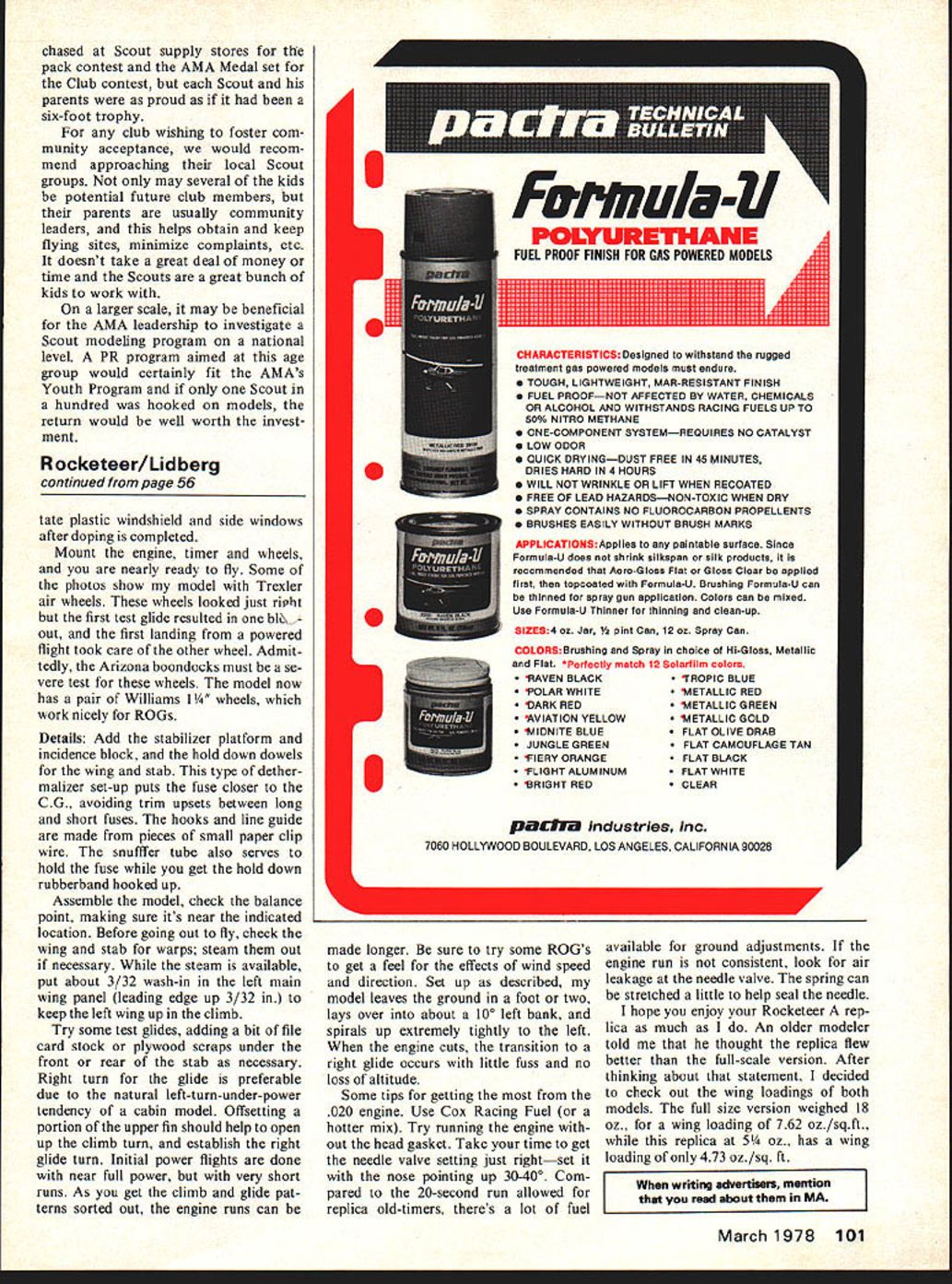
Some tips for getting the most from the .020 engine. Use Cox Racing Fuel (or a hotter mix). Try running the engine without the head gasket. Take your time to get the needle valve setting just right—set it with the nose pointing up 30-40°. Compared to the 20-second run allowed for replica old-timers, there's a lot of fuel available for ground adjustments. If the engine run is not consistent, look for air leakage at the needle valve. The spring can be stretched a little to help seal the needle.
I hope you enjoy your Rocketeer A replica as much as I do. An older modeler told me that he thought the replica flew better than the full-scale version. After thinking about that statement, I decided to check out the wing loadings of both models. The full size version weighed 18 oz., for a wing loading of 7.62 oz./sq. ft., while this replica at 5-1/4 oz., has a wing loading of only 4.73 oz./sq. ft.
Transcribed from original scans by AI. Minor OCR errors may remain.

