
Ronceur
Author
- Chuck Rudner
Overview
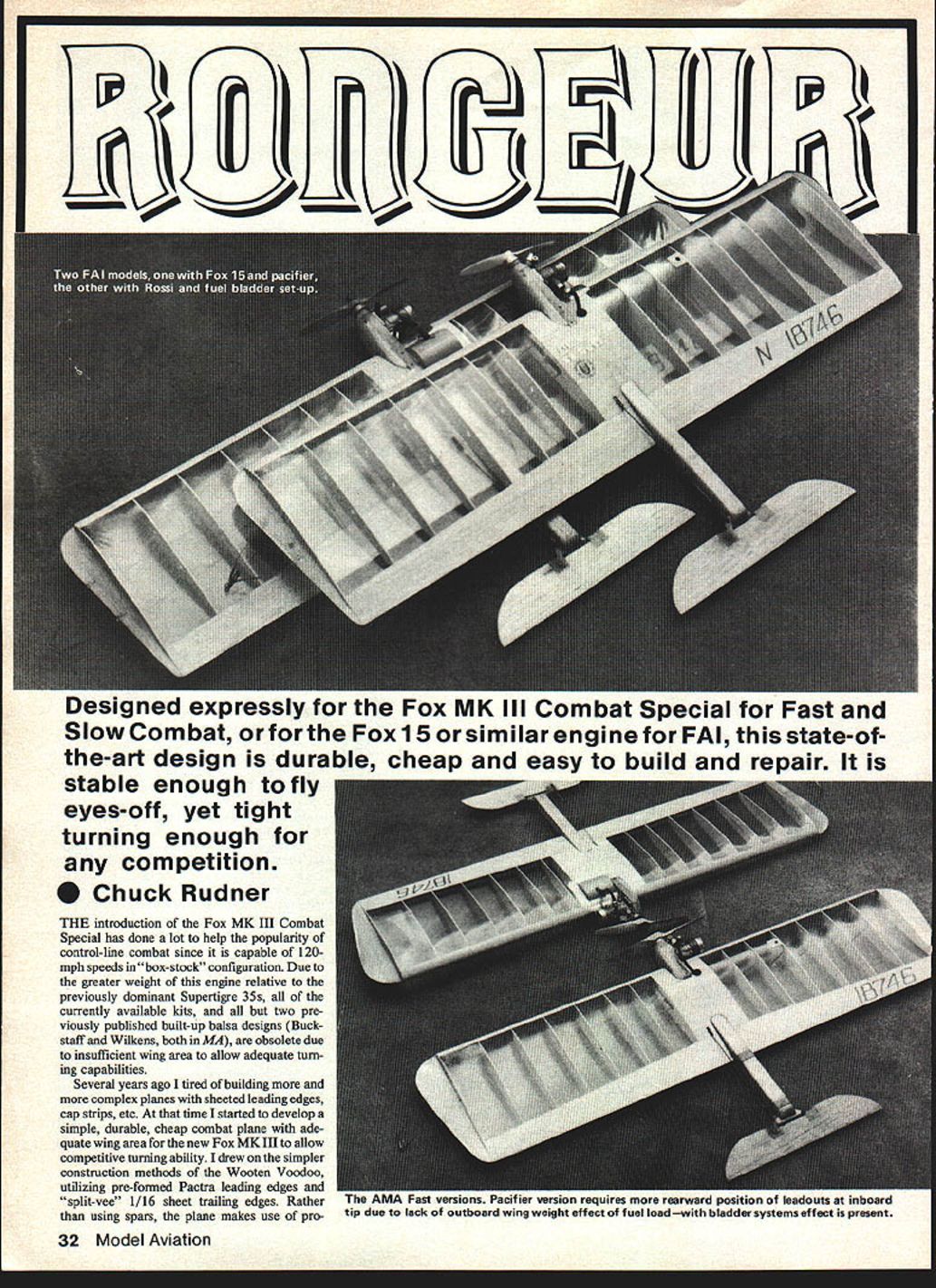
Designed expressly for the Fox MK III Combat Special for Fast and Slow Combat, or for the Fox 15 or a similar engine for FAI, this state-of-the-art design is durable, cheap and easy to build and repair. It is stable enough to fly eyes-off, yet tight-turning enough for competition.
The introduction of the Fox MK III Combat Special has helped the popularity of control-line combat because it is capable of 120 mph in "box-stock" configuration. Due to the greater weight of this engine relative to the previously dominant Supertigre .35s, many previously available kits and most older built-up balsa designs are now obsolete because they lack sufficient wing area for adequate turning capability.
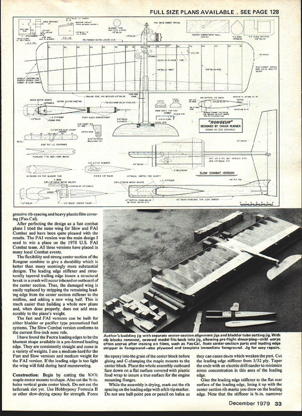
Several years ago I tired of building increasingly complex planes with sheeted leading edges, cap strips, etc. I then developed a simple, durable, inexpensive combat plane with adequate wing area for the Fox MK III. I drew on the simpler construction methods of the Wooten Voodoo, utilizing pre-formed Pactra leading edges and "split-vee" 1/16" sheet trailing edges. Rather than using spars, the plane uses progressive rib spacing and heavier rib construction in the center section.
After perfecting the fast-combat design, I adapted the same wing for a Slow FAI combat version with pleasing results. The FAI version of the main design was used by the 1978 U.S. FAI Combat team; three versions have placed in local events. Flexibility and a strong center section yield durability better than seemingly more substantial designs. A leading-edge stiffener and structurally tapered trailing edge help ensure that, when structural breakage occurs in a crash, it will be inboard or outboard of the center section—so a damaged wing half can be replaced without rebuilding the whole plane. Proper repair does add measurable weight, however.
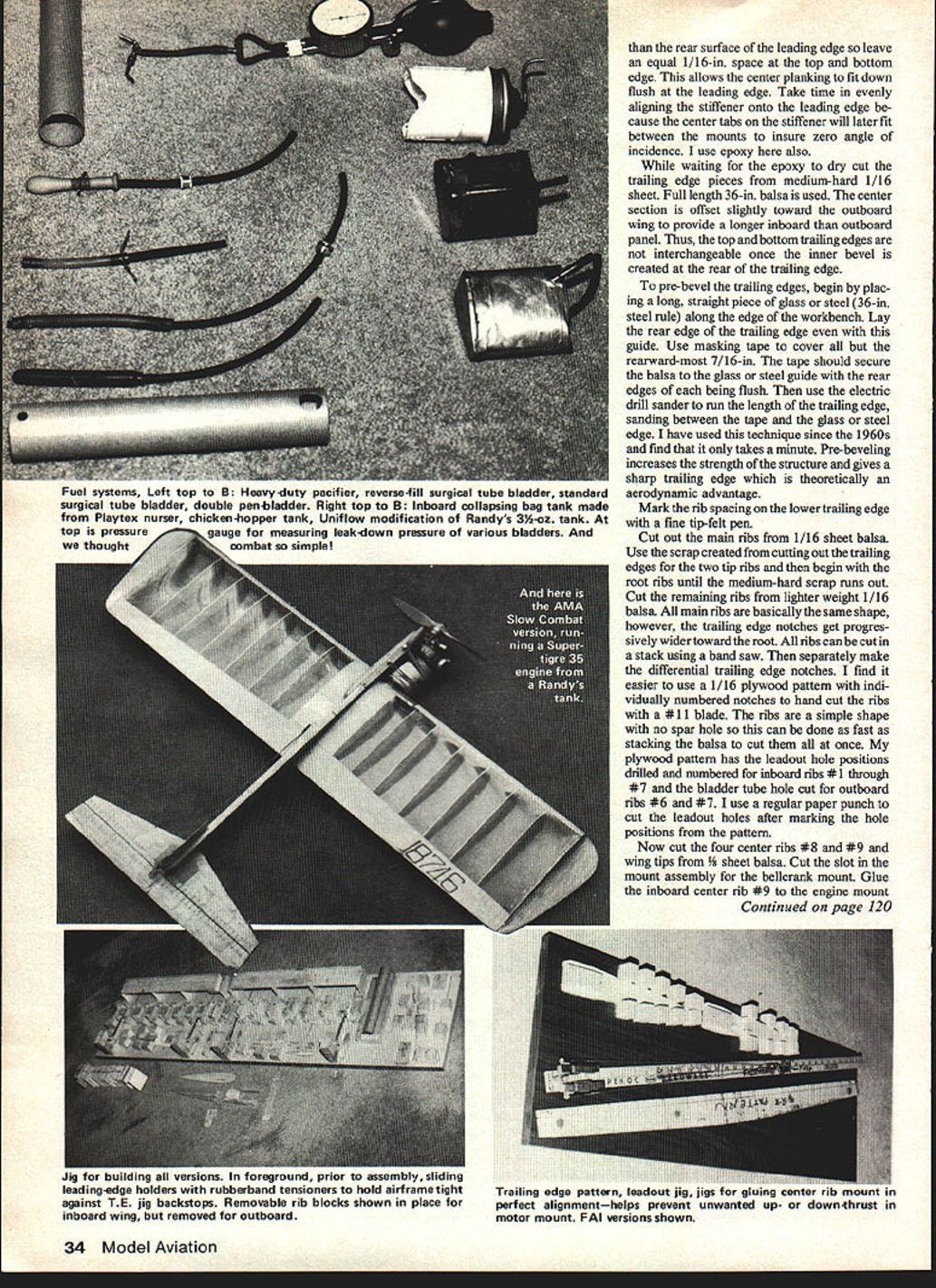
Fast and FAI versions can be built for either bladder or pacifier-type pressurized fuel systems. The Slow Combat version conforms to the current five-inch nose rule.
I have found Pactra preformed leading edges—the bluntest shape available—consistently straight and available in various densities. Use medium-hard for Fast and Slow versions; medium for the FAI version. If the leading edge is too light the wing will fold during hard maneuvering.
Materials & adhesives (selected)
- Leading edge: Pactra preformed leading edge (medium-hard or medium)
- Leading-edge stiffener: 3/32" plywood
- Main ribs: 1/16" sheet balsa (medium-hard for root ribs)
- Center ribs and tips: 1/8" sheet balsa
- Center block: 1/2" vertical-grain balsa
- Motor mounts: 1/8" x 3/32" maple
- Trailing edge: full-length 36" 1/16" balsa sheet (split-vee)
- Monoboom: 1" sq. medium-hard balsa
- Bellcrank: interlocking plywood with 3/32" O.D. brass tube hinge
- Adhesives: Hobbypoxy Formula II (slow epoxy), 5-minute epoxy, Ambroid cement, Hot Stuff (CA), epoxy paint
- Covering: Fas-Cal
- Misc: 1/16" music wire pushrod, 1/8" hardwood dowels, 4/40 machine screws and blind nuts, brass tubing for leadout bushings, Perfect braided leadouts (125 lb test), Kwik Link, nylon control horn
Construction
#### Motor mounts and center block
- Cut the 1/8" x 3/32" maple motor mounts to shape.
- Cut the 1/2" vertical-grain balsa center block. Do not cut the bellcrank slot yet.
- Use Hobbypoxy Formula II or another slow-drying epoxy for strength. Force epoxy into the grain of the center block before gluing and C-clamping the maple mounts to the center block.
- Place the whole assembly outboard face down on a flat surface covered with plastic food wrap to ensure a true surface for the engine-mounting flanges.
While this assembly dries, mark the rib spacing on the leading edge with a fine-tip felt marker (do not use ballpoint pen or pencil, which can dent balsa).
#### Leading-edge stiffener
- Cut the leading-edge stiffener from 3/32" plywood.
- Taper the ends with an electric drill and sander to minimize stress concentration.
- Glue the stiffener to the flat rear surface of the leading edge, lining it up with the center-section rib marks. Note the stiffener is slightly narrower than the leading edge—leave an equal 1/16" space at the top and bottom edge so the center planking fits flush.
- Take time to align the stiffener evenly; the center tabs on the stiffener will later fit between the mounts to ensure zero angle of incidence. Epoxy is recommended.
#### Trailing edge preparation
- While waiting for epoxy to dry, cut trailing-edge pieces from medium-hard 1/16" sheet. Use full 36" lengths.
- The center section is offset slightly toward the outboard wing to provide a longer inboard than outboard panel. Because of this, top and bottom trailing edges are not interchangeable once the inner bevel is created.
- To pre-bevel the trailing edges: place a long straight glass or steel guide (e.g., a 36" steel rule) along the workbench. Lay the rear edge of the trailing edge even with the guide. Cover all but the rearmost 7/16" with masking tape to secure the balsa to the guide. Use an electric drill sander to sand between the tape and the guide along the length. Pre-beveling increases structure strength and yields a sharp aerodynamic trailing edge.
- Mark rib spacing on the lower trailing edge with a fine-tip felt pen.
#### Ribs
- Cut main ribs from 1/16" sheet balsa. Use the scrap from cutting trailing edges for two tip ribs; begin with root ribs while the medium-hard scrap remains, then use lighter 1/16" balsa for the rest.
- All main ribs are basically the same shape; trailing-edge notches get progressively wider toward the root.
- Ribs can be cut stacked on a bandsaw. I use a 1/16" plywood pattern with individually numbered notches to hand-cut ribs with a #11 blade, and pre-drill or mark leadout hole positions for inboard ribs #1–#7 and bladder tube hole for outboard ribs #6 and #7. Use a paper punch for leadout holes.
- Cut four center ribs (#8 and #9) and wingtips from 1/8" sheet balsa.
- Cut the slot in the mount assembly for the bellcrank mount.
#### Center-rib and mount assembly
- Glue inboard center rib #9 to the engine mount assembly on its inboard side. It is critical to position this rib parallel to the motor-mount axis to avoid up- or down-thrust in the motor mount. Use a small balsa jig fixture for alignment and 5-minute epoxy for gluing.
- After drying, glue the horizontal-grain 1/8" sheet center rib filler and the interlocking plywood bellcrank mount to the assembly with epoxy.
#### Wing assembly
- Omit outboard ribs #5–#8 for bladder-tube versions, or omit outboard rib #8 for pacifier versions, until the bladder/pod is installed.
- Use Hot Stuff and microballoons to fix the two tip ribs, outboard rib #9, and inboard rib #7 to the leading and trailing edges. Ambroid suffices for cementing the remaining ribs.
- The rib template includes a "Symmet-tru" tab (as in Goldberg Voodoo kits) on inboard and outboard ribs #1 and #7. Pre-perforate these tabs so they snap off after construction—this helps build the wing warp-free on a flat surface. A specially constructed jig can eliminate the need for tabs, speed construction and repair, and allow warp correction after covering.
- Mount the engine to the motor mounts at the location shown on the plans.
#### Engine alignment (zero thrust)
- Remove the glow plug and bolt a spare prop onto the crankshaft.
- Attach a heavy thread to the tip of the prop and a clamp-type paper clip that can slide on the string.
- Adjust up-and-down thrust so the distance from the upper and lower maximums of prop arc to the trailing-edge tip of the center rib is equal. Rotate the prop 180° each time and check distances. When zero up/down thrust is achieved, bolt the engine with 4/40 machine screws and blind nuts.
- Remove the engine and hook up the 2" bellcrank with leadouts and a 1/16" music wire pushrod to the bellcrank mount. I use 125-lb-test Perfect braided leadouts bushed at the bellcrank with brass tubing. The pushrod goes in the outer hole of the bellcrank arm.
- Drill holes for 1/8" hardwood dowels with a 5/32" drill and cement them in place with epoxy.
- Using Hobbypoxy II, glue the center-section unit against outboard rib #9. The tabs on the leading-edge stiffener assure zero angle of incidence.
- Glue the upper trailing-edge half in place (Ambroid for most joints; use 5-minute epoxy for the joint between the center section and the trailing edge).
#### Bladder tube or pacifier pod installation
- Bladder tube:
- Cut to length from an Estes BT-55 rocket body to fit between outboard ribs #9 and #5.
- Punch upper and lower vent holes and a large bladder exit hole. Cap with vertical-grain 1/8" balsa.
- Cement the bladder plate in place with ribs #5, #6, and #7, then add the parts of outboard rib #8.
- Use 1/16" scrap filler at vent holes to provide anchorage for the Fas-Cal covering.
- Finish the inside of the bladder tube by filling it with clear dope and pouring it out (this smooths the inside; epoxy paint can create sharp flaws from specks of sawdust that puncture bladders).
- Pacifier pod:
- Fashion from 1/64" plywood walls with 1/8" balsa end caps and a small vent hole in the bottom outboard corner.
- Glue it to outboard rib #9 and glue outboard rib #8 to it, sandwiching it in place.
#### Sheeting and center section
- Sheet the center section with 1/16" sheet. Make sure you glue the sheeting to the center rib unit with epoxy.
- If instructions were followed, the entire center rib unit and its sheeting will be glued with epoxy. A fairly massive center section helps damp engine vibration and prevents loosening at the monoboom-wing junction from repeated hard maneuvering or crashes.
- Glue wing tips in place and glue and sew leadout guides into the inboard tip.
Tail construction
- The hinge is shown on the plans as four separate plywood parts sandwiching a 3/32" O.D. brass tube. Alternatively, make 12" strips of brass tubing sandwiched between plywood, then cut each hinge out of this strip with a jigsaw. Use epoxy for fabrication.
- Add the wire axle with brass tubing spacers and bend to shape. Cement it to the pre-airfoiled stabilator; cloth tape epoxied over the tubing spacers and stabilator leading edge secures it.
- Pre-airfoil the stabilator by drawing a ballpoint-pen midline around the perimeter and free-hand sanding with an electric drill sander—fast and effective.
- Cut the medium-hard 1" sq. balsa monoboom to shape with a jigsaw. Cement the hinge into it, aligning the stabilator trailing edge perpendicular to the monoboom with a drafting triangle.
- Add a large nylon control horn and finish the tail assembly with epoxy paint. Reinforce the monoboom with a circumferential loop of fiberglass tape just aft of the wing slot and at the rear where the hinge is glued.
- Install a large nylon control horn, a Kwik Link, and a wire pushrod guide. Do not omit the pushrod guide—outside-maneuver aerodynamic forces will bow the pushrod and reduce control effectiveness without it.
Covering and finishing
- Cover the wing carefully with Fas-Cal, laying it on all surfaces with the same initial tension to minimize warps.
- After covering and shrinking, replace the wing in the jig and remove any warp by holding pressure against the warp and re-ironing the Fas-Cal. If a jig is not used, detect gross warps by eyeballing along the trailing edge.
- Mask off the center section while sanding the motor-mount nacelle and filler blocks into shape with a drill sander to avoid slips that could damage the plane.
- Finish the mount with epoxy paint and fiberglass cloth.
Monoboom installation
- Excise covering from the sheeting where the monoboom will be glued and perforate the sheeting many times with a pin through to the center rib for mechanical keying.
- Epoxy the monoboom to the wing with Hobbypoxy Formula II to allow ample working time to align the tail with the wing.
- Sight down the trailing edges of both wing and stabilator from the rear to align them in the roll axis. Use a ruler to equalize the distance between wing trailing edge and stabilator trailing edge for platform alignment.
Variants and setup
- Slow Combat: uses the same wing with a standard balsa fuselage and standard-type nose. Two pushrod guides are required along the longer fuselage.
- Fast Combat: power with an MK III Fox Combat Special using 25% nitro and head clearance set to .019".
- FAI version: power with a high-performance .15 (I prefer the Fox 15). Select slightly lighter wood for the FAI version.
Weights and balance:
- Fast Combat (without engine): 8-1/2 to 9 oz.
- FAI version (without engine): 8 to 8-1/2 oz.
- The plane should balance with motor and prop installed at 18.5% of the chord, which is 1-1/4" rear of the leading edge. Place the bladder tube exactly along this line to prevent CG change as fuel is consumed. With this CG, the second hole from the top of the control horn is a good starting point.
Final checks and flight
- Install leadouts, ensure all joints are secure, and confirm pushrod routing and guides are in place.
- Take a test flight to check for warps and thrust misalignment; if construction care was taken these are usually minimal.
- The Ronceur provides a durable, inexpensive, easy-to-build and -repair combat plane that is stable enough to fly eyes-off while turning tightly for competition.
Transcribed from original scans by AI. Minor OCR errors may remain.

