
Rose Parrakeet
Frank Beatty
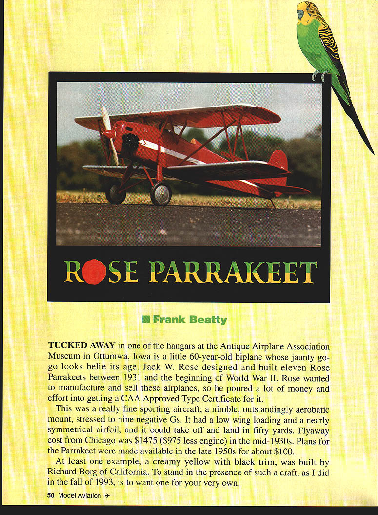
Tucked away in one of the hangars at the Antique Airplane Association Museum in Ottumwa, Iowa is a little 60‑year‑old biplane whose jaunty, go‑go looks belie its age. Jack W. Rose designed and built eleven Rose Parrakeets between 1931 and the beginning of World War II. Rose wanted to manufacture and sell these airplanes, so he poured a lot of money and effort into getting a CAA Approved Type Certificate for it.
This was a really fine sporting aircraft: a nimble, outstandingly aerobatic mount, stressed to nine negative Gs. It had a low wing loading and a nearly symmetrical airfoil, and it could take off and land in fifty yards. Flyaway cost from Chicago was $1,475 ($975 less engine) in the mid‑1930s. Plans for the Parrakeet were made available in the late 1950s for about $100.
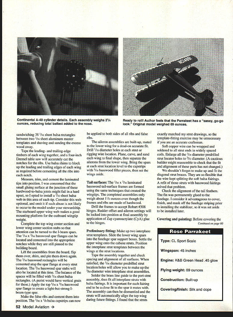
At least one example, a creamy yellow with black trim, was built by Richard Borg of California. To stand in the presence of such a craft, as I did in the fall of 1993, is to want one for your very own.
Björn Karlström's three views from the April 1972 American Aircraft Modeler were used to prepare the working drawings of the Parrakeet. Two additional three‑views, lengthy photo‑spread articles with color centerfolds in Sport Flying (June 1969 and April 1970), Air Progress (May 1969), Bob Banka's Scale Model Research Foto‑Paaks of the plane (#1347) and Continental A‑40 Engine (#436) contributed in some measure to painting and detailing of the model.
My model attempts to follow Karlström's drawings, which depict the aircraft in its 1936 form. However, over the years the surviving Parrakeets have been modified in many ways. More powerful engines with cowlings to suit, low‑pressure donut‑type wheels, tailwheels, and navigation light systems have been fitted. Variations in windshields, cockpit coamings, wing walks, etc., are rife.
My model would probably be classified in the Sport Scale Category because it is a composite of markings and additional details taken from several different planes in the sources listed above.
One significant change must be mentioned. Close examination of the two other three‑views and of dead‑on side‑view photos of several of these planes indicated that they all had noticeably longer noses than shown in Karlström's drawings. Since it is easier to balance a model with a longer nose, I opted to lengthen the nose by about one inch and to shorten the tail by about one inch. Each modeler should conduct his own research and use those findings to build a model to suit his particular goals.
Mr. Karlström's drawings were scaled up four times their original size to build a model to a scale of 2 1/4 inches to the foot. The model has a 45‑inch wingspan and 35‑inch length — a nearly ideal size for me, and it just does shoehorn into my four‑door sedan.
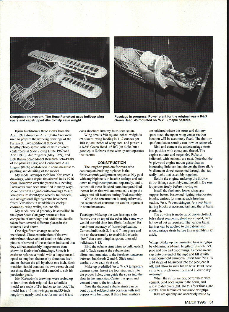
Wing area is 590 square inches; weight is 69 ounces; wing loading is 11.7 ounces per 100 square inches of wing area; and power is a K&B Green Head .45 RC (an oldie, but a goodie). A Roberts three‑wire system operates the throttle.
CONSTRUCTION
The toughest problem for most who contemplate building biplanes is the finish/assembly/alignment sequence. My goal with any biplane is to be able to dope and rub down all major components separately, and to cement all these finished parts into predrilled locator holes that will automatically align the wings and tail feathers during final assembly.
While the construction is straightforward, the sequence of construction can be important in some instances.
Specifications
- Type: CL Sport Scale
- Wingspan: 45 inches
- Engine: K&B Green Head .45 glow
- Flying weight: 69 ounces
- Construction: Built‑up
- Covering/finish: Silk and dope
Fuselage
- Make up the two fuselage side frames, one on top of the other (the same way we did our old‑time free‑flight fuselages) for maximum accuracy of frame duplication.
- Cement bulkheads 2, 4 and 7 into place and true up the assembly to establish the basic "box" that everything hangs on; then add bulkheads 8–13.
- Bind the cabane strut wires to bulkheads 2 and 4. Tack‑cement the cabane strut alignment templates to the fuselage longerons between bulkheads 2 and 4. Slide small washers onto each strut end.
- Make up predrilled 3/8 x 3/4 x 7 temporary dummy spars. Insert four strut ends into the proper holes and guide spars into the slots in the templates. Center spars and cement templates. Now diagonal cabane struts can be bent up and soldered in position, using soft copper wire bindings. If those four washers are soldered where the struts and dummy spars meet, the upper wing center section location will be accurately fixed. The dummy spar/template assembly can now be removed.
- Bind and cement the undercarriage struts into position with epoxy and thread.
- Install the engine mounts and suspended Roberts bellcrank with leadouts. Note that the 1/8" plywood engine mount gusset has an interesting little tab that pierces the firewall. A 1/8" diameter dowel cemented through that tab really locks the assembly together.
- Bolt in the engine, make up the throttle throw linkage assembly, and install it. Be sure it operates freely before moving on.
- Install the fuel tank, lower wing spar support boxes, basswood rigging wire locator blocks, various formers at each fuselage station, 1/16 x 1/8" bass stringers, 1/8" sheet balsa fairing blocks at nose and tail, and the 1/8" balsa planking.
- The cowling is made up of one‑inch‑thick balsa sheet segments, glued up, shaped, and hollowed out as required. The various balsa fairings can be applied to the cabane and undercarriage struts before this assembly is set aside.
Wings
- Wingtips:
- Make up the laminated basswood wingtips by obtaining a 24‑inch length of 3/8" PVC pipe and two end caps. Cement an end cap onto one end of the pipe and fill it with clear household ammonia. Insert four 1/16 x 1/4 x 14 strips of basswood into the pipe, cap it, and allow to soak for an hour.
- Bind the laminate to a plywood form and allow to dry overnight. When the strips are dry, cover them with cement, bind once again to the form, and allow to dry overnight. Do this four times to produce four laminated basswood wingtips.
- Measure, trim, and cement the laminated tips into position. I was concerned that the small gluing surface at the junction of these hardwood‑to‑balsa joints might fail in a hard upset, so I opted to install a 3/32" sheet balsa web in this area of each tip. Consider this web optional and omit it if such abuse is not likely. The starboard upper wing web makes a good mounting platform for the outboard wingtip weight.
- Ribs and spars:
- Ribs are quickly and accurately made by using a simple jig and the capstrip method. One handy technique for producing uniform rib pieces is sandwiching 3/8 x 1/16" sheet balsa rectangles between two 1/16" sheet aluminum master templates and shaving and sanding the excess wood away.
- The Parrakeet uses built‑up wing spars and capstripped ribs to help save weight. Construct the spars, assemble the ribs on the jig, then add the capstrips. Notch ribs as required for spars and shear webs, and sand to section.
- The 1/16 x 3/16" basswood spar flanges can be located and cemented into the appropriate notches while pinned to the building board. Lift the assemblies, flip them over, shim, and pin them down again. Cement 3/16" basswood rectangles atop the spar flange at every strut location. The 3/16" basswood spar stubs will also be located at this time. Fill the balance of spaces with 1/16" sheet balsa rectangles (vertical grain preferred). Apply the top 1/16 x 3/16" basswood spar flange to create a light‑but‑strong I‑beam‑type spar.
- Assembly:
- Tape the leading‑ and trailing‑edge timbers of each wing together, and use a four‑inch Dremel table saw to accurately cut the notches for the ribs. Use balsa slabs to block up the leading and trailing edges of each wing as required before cementing all the ribs into each notch.
- Complete the top center section and lower wing center section stubs so that attention can be turned to the I‑beam spars. Make the false ribs and cement them into position. Apply 1/16 x 1/8" balsa capstrips to both sides of all ribs and false ribs.
- Assemble the lower wings first, installing ailerons where shown on the plans. Make up the center‑section and attach the cabane struts; check rigging and incidence carefully before cementing final joints. The upper wing center section is fitted to the cabane and the interplane struts positioned and checked for proper stagger and incidence. Bind and cement struts in place and install the flying and landing wire rigging as per the plans.
- Plane, carve, and sand each wing to final shape, then separate the ailerons from the lower wing. Bring the spars at each strut location level to the capstrips with 1/16" basswood filler pieces, then set the wings aside.
Tail surfaces
- The 1/16 x 3/16" laminated basswood tail‑surface frames are formed using the same techniques that created the wingtips. The completed assemblies weigh only about 1½ ounces even though the frames and ribs are made of hardwood.
- Drill the frames to accept Robart #308 hinges. Rudder offset and aileron settings will be locked into position at final assembly by application of Zap cyanoacrylate (CyA) glue to the hinges.
Preliminary fitting
- Make up two interplane strut templates. Slide the lower wing spars into the fuselage spar support boxes. Settle the upper wing onto the cabane struts. Position the interplane strut templates between the wings at the strut locations.
- Tape the assembly together and check spacing and alignment of all surfaces. When satisfied, the 1/16" diameter predrilled strut location holes will allow you to make up the 3/64" diameter wire interplane strut assemblies.
- Solder the brass line guide to the port strut assembly, then fit all interplane struts and balsa fairings. It is important for each fairing to be a close fit to the spar it mates with. The assembly can then be dismantled and the struts will automatically align the top wing during future fittings.
- Soft copper wire can be wrapped and soldered to all strut ends in widely spaced coils. Enlarge all the 1/16" diameter predrilled strut locator holes to 3/32" diameter. (A cautious builder might reassemble to check that the fit and alignment of these parts has not changed.)
- Make up and fit the diagonal strut braces. These are so flexible that the wire kept splitting the soft balsa fairings; refitting those struts with basswood fairings solved that problem.
- Check the alignment of the tail feathers. The fin was permanently glued to the fuselage. I consider it advantageous to cover, finish, and mask off the fuselage striping prior to installation of the stabilizer, so it was set aside to be installed later.
Covering and painting
Before covering the model, "break" (round off) the corners of all hardwood stringers or other hardwood members to reduce the possibility of sharp, hard corners cutting through the covering material during finishing.
- All components, including the struts, were covered with silk. Prick a pinhole in the covering at each predrilled strut or rigging wire locator hole, or these will be lost under the coats of paint to come.
- Use your favorite method to finish your model. I used four to six coats of brushed clear dope, followed by eight thinned spray filler coats, followed by eight thin sprayed color coats with a wet‑or‑dry sanding thrown in every two or three coats. A final gloss finish was achieved with a medium‑grade rubbing compound. Take it easy on the sanding and rubbing, because you can easily cut through the fabric if you are too ham‑handed.
- Give the model a thorough cleaning with soap and water. The trim was achieved with a combination of masking tape and stencils. The color scheme, markings, and instrument panel layout were derived from photos in the May 1969 Air Progress.
Final assembly
- Details like the instrument panel, windshield, leather cockpit padding, and wing walks should be added at this time.
- Install the lower wings by cementing the spar stubs into the spar support boxes. Coat the lower interplane strut ends with epoxy and mate them to the lower wings.
- Make a jig to help locate and align the rigging wires and diagonal strut braces. Take two lengths of 1/4 x 1/2 x 32" spruce and drill 3/32" diameter holes in them to match the upper wing strut/rigging locator holes. Slide these dummy spars into position on the model's cabane and interplane struts.
- Now the rigging wires and diagonal strut braces can be located and epoxied to the fuselage and lower wings at the correct angles to mate with the upper wing. Let this dry overnight before removing the dummy spars.
- You then have fourteen, floppy rigging wire or strut ends to butter with epoxy and slide into the proper holes in the upper wing — a dicey, potentially messy job for one person. Extra hands make this much easier. Tape the assembly, check alignment one final time, and allow to dry overnight.
- Install the stabilizer/elevator unit and solder the pushrod connection. The ailerons and rudder are attached with Robart hinges. These hinges are CA'ed for about 3/8" offset in the rudder, with ailerons deflected 1/16" up on the starboard and 1/16" down on the port to maintain line tension when flying.
- Neat scale rigging wire fittings can be fabricated from brass tubing. The drawings explain this installation.
- About all that is left is the dummy engine cylinders. Early on, I realized that ballast would be required in the nose. Accordingly, the cylinders were purposely made of heavy, durable materials like plywood and metal tubing; they weighed 4½ ounces. An additional four ounces was added to the model's nose.
- If you have a scroll saw you can stack and saw all of one kind of part at one time, which will speed things up and assure uniformity. After each unit is made up, a cavity must be carved into the cowl to accept the cylinder's base. If one works carefully, it is not a major problem if this operation is saved for last.
Flying
- This model has a good configuration for CL flying. The wheels are large, widely spaced, and located well forward for good ground handling.
- The model has a fairly high wing loading and ample power. It has aerobatic potential if kept light, or contest‑winning potential if detail and finish are piled on.
- The scale semisymmetrical airfoil can provide some stunt capability if weight is more carefully monitored than I managed.
- Build and finish to suit your own inclinations, but do not fly your model unless it is balanced at or forward of the center of gravity (CG) location noted on the drawings.
Enjoy!
Transcribed from original scans by AI. Minor OCR errors may remain.

