
Roto Raven
IN THE WORLD of high-performance thermal soaring, Roto-Flap is new, challenging, and exciting. A highly effective and practical system of control for the thermal soarer, it may provide a basis for developing a new generation of sophisticated soaring machines yielding unprecedented performance levels.
The boxy Roto-Raven is a quick and easy way to get acquainted with Roto-Flap while amply demonstrating the system's viability and potential.
Roto-Flap offers the following advantages:
- Ailerons and elevator (or all-moving stab) are eliminated.
- Camber changes are accomplished by one servo operating long, dedicated flaps.
- Airspeed for precision landings is much slower than in "crow" (flaps down, ailerons up), and the ship still turns very well.
- The overall hardware count and current drain are reduced.
- Airframes can be simpler and lighter.
- No more than a four-channel receiver is needed.
- Only the most commonly used transmitter controls are needed.
In contrast to conventional use of as many as four servos for camber/flap operations, Roto-Flap does it all with one. This greatly simplifies installation and operation.
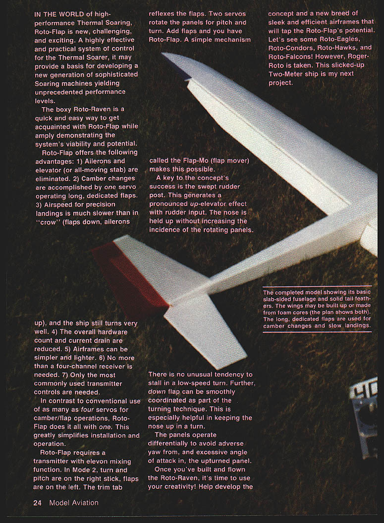
Roto-Flap requires a transmitter with elevon mixing function. In Mode 2, turn and pitch are on the right stick, flaps are on the left. The trim tab reflects the flaps. Two servos rotate the panels for pitch and turn. Add flaps and you have Roto-Flap. A simple mechanism called the Flap-Mo (flap mover) makes this possible.
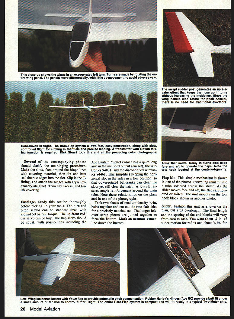
A key to the concept's success is the swept rudder post. This generates a pronounced up-elevator effect with rudder input. The nose is held up without increasing the incidence of the rotating panels.
There is no unusual tendency to stall in a low-speed turn. Further, down flap can be smoothly coordinated as part of the turning technique. This is especially helpful in keeping the nose up in a turn.
The panels operate differentially to avoid adverse yaw from, and excessive angle of attack in, the upturned panel.
Once you've built and flown the Roto-Raven, it's time to use your creativity. Help develop the concept and a new breed of sleek and efficient airframes that will tap Roto-Flap's potential. Let's see some Roto-Eagles, Roto-Condors, Roto-Hawks, and Roto-Falcons! (Roger-Roto is taken.) This slicked-up two-meter ship is the author's next project.
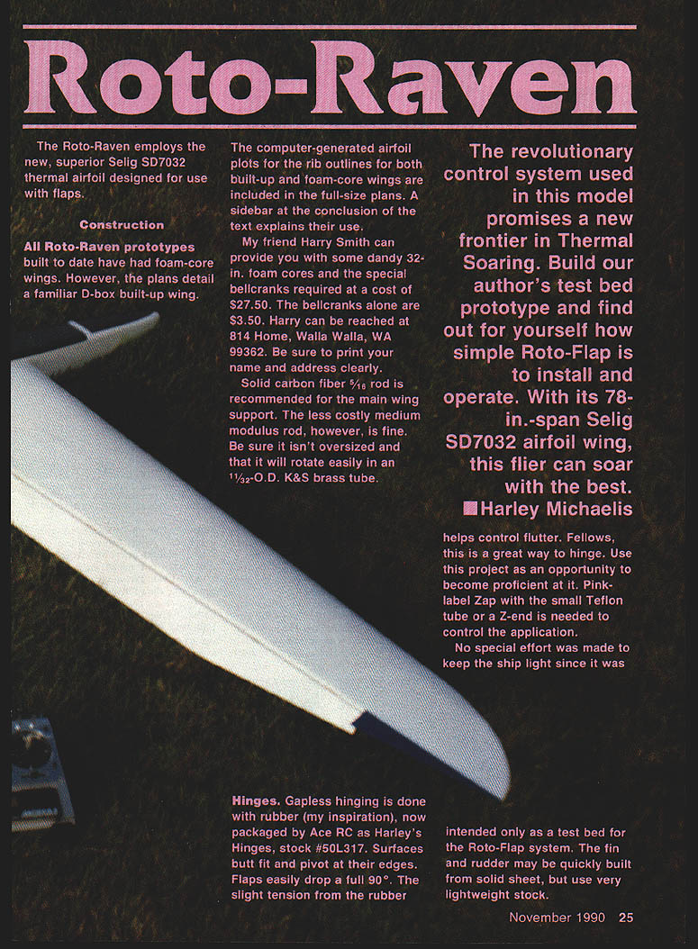
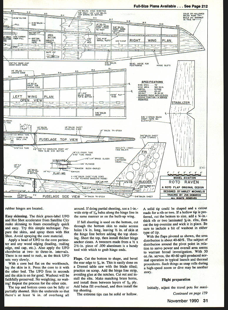
The Roto-Raven employs the Selig SD7032 thermal airfoil designed for use with flaps.
Construction
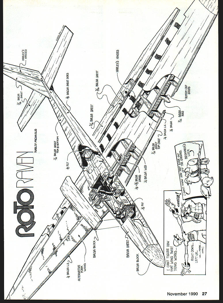
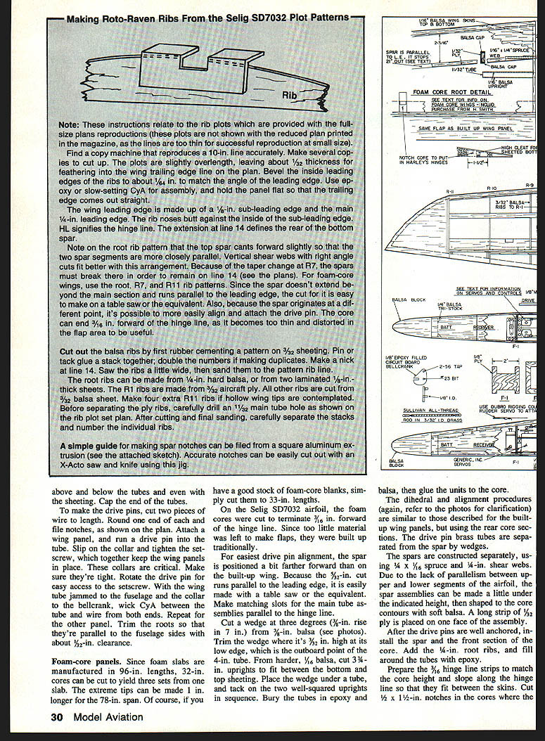
All Roto-Raven prototypes built to date have had foam-core wings; however, the plans detail a familiar D-box built-up wing. The computer-generated airfoil plots for rib outlines (for both built-up and foam-core wings) are included in the full-size plans. A sidebar in the plans explains their use.
Materials and suppliers:
- My friend Harry Smith can provide 32-oz foam cores and the special bellcranks for $27.50; bellcranks alone are $3.50. Harry can be reached at 814 Home, Walla Walla, WA 99362. Be sure to print your name and address clearly.
- Solid carbon fiber 5/16" rod is recommended for the main wing support. Medium modulus rod is acceptable. Ensure it is not oversized and that it will rotate easily in an 11/32" O.D. K&S brass tube.
The Roto-Flap control system promises a new frontier in thermal soaring. Build the author's test-bed prototype and discover how simple Roto-Flap is to install and operate. With its 78" span Selig SD7032 wing, this flier can soar with the best. — Harley Michaelis
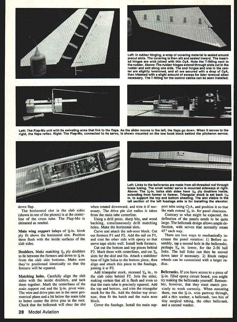
Hinges
Gapless hinging is done with rubber (Harley's inspiration), now packaged by Ace RC as Harley's Hinges, stock #50L317. Surfaces butt-fit and pivot at their edges. Flaps easily drop a full 90°. The slight tension from the rubber helps control flutter. This is a great way to hinge; use this project as an opportunity to become proficient.
Adhesive notes:
- Use pink-label Zap with the small Teflon tube or a Z-end to control application.
- A small Teflon tube or Z-end helps control CyA application when attaching hinges.
No special effort was made to keep the test-bed ship ultra-light. The fin and rudder may be quickly built from solid sheet, but use very lightweight stock.
Hinge installation summary:
- Make the hinge slots and face around the hinge lines.
- Slit the covering material, then slit and heat-seal the raw edges into the slot.
- Slip in the T-fitting and attach hinges with CyA (cyanoacrylate).
- Trim any excess and finish covering.
Fuselage
Study this section thoroughly before cutting parts. Recommended servos:
- Turn and pitch servos: standard-sized, around 50 oz-in torque.
- Rudder servo (up-front): can be tiny.
- Flap servo: squat profile; candidates include Ace Bantam Midget (long arm available), Airtronics 94831, or similar.
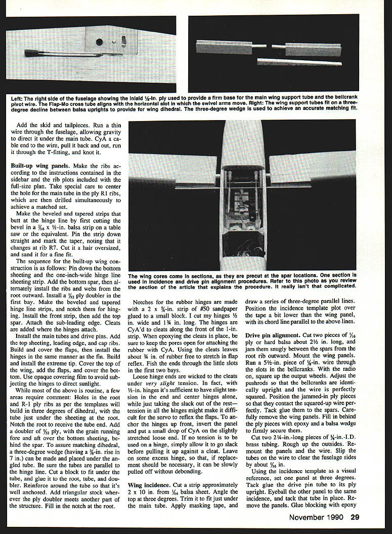
A low horizontal slot in the sides makes it easier for down-rotated bellcranks to clear the slots and hatch, and ensures ample reinforcement around the main tube. Note these relationships on the plans and in the photos.
Basic fuselage construction:
- Tack two sheets of medium-density 1/8" balsa together and cut out the two slab sides for a precisely matched pair.
- Join longer leftover scrap pieces to form the bottom. Mark an accurate centerline down the bottom.
- Carve and attach the sub-nose block.
- Cut out formers F1 and F2 and install them (coat the side to receive servos with epoxy—servo tape sticks well).
- Cut out bottom and top pieces behind F2. Mark centerlines. Cut 3/64" slots for skid and fin.
- Attach stabilizer base (light balsa bottom piece) aligned to F2.
- Add triangular stock recessed 1/16" into slab sides behind F2. Join sides, ensuring they are flush and the main tube is precisely squared.
- Add top and bottom trim triangular stock and thicker top structure to fit the hatch and main nose block.
- Cover the fuselage.
#### Main wing support inlays
- 1/8" birch ply inlays fit above the horizontal slot. Position flush with the inside surfaces of the slab sides.
#### Doublers
- Make matching 1/32" ply doublers to fit between formers at the slab-side bottoms. Position them identically or the formers will not square.
#### Matching holes
- Carefully align slab sides inside doublers and tack together.
- Mark centerlines and locations for the main support rod, 1/8" pivot wire, and drive pins so they are in the same geometrical plane.
- A bit below the main tube is better to center drive pins at the root.
- Check that the bellcrank clears the slot when rotated downward; trim the drive-pin slot radius from the main-tube centerline as needed.
- Using a drill press, sharp bits, and wood backing, simultaneously drill matching holes.
After drilling and slots:
- Install main support tube using CyA; position ends to extend about 1/8" past panel clearance.
- Add skid and tailpieces. Run a thin wire through the fuselage, allow gravity to direct it under the main tube, CyA a cable end to the wire, pull it back and out, run it through the T-fitting, and knot it.
Bellcranks and panel deflection:
- Contrary to expectation, panel deflection needs to be quite large. The bellcrank design allows ample deflection; servos normally rotate about 45° each way.
- Two mechanical ways to increase panel rotation:
- Before assembly, tap a second hole in the bellcranks (for example, about 3/16" lower) so the ball links can be mounted lower.
- Use 2-56 ball links or customize blank output arms with a larger radius.
Bellcrank construction tip:
- If you can access 3/16" filled epoxy circuit board, you might make bellcranks yourself. Ensure they match precisely. When mounting: run the ends of the 1/8" wire partway through, add a thin washer, a bellcrank, two bits of tiny surgical tubing, the other bellcrank, and a second washer.
Flap-Mo
The Flap-Mo is a simple mechanism: swiveling arms fit into a tube soldered across a slider. As the slider moves fore and aft, the flaps are lowered or raised. The unit mounts on the tow-hook block behind the pitch-eron servos. Flap-Mo swiveling arms link the flaps; as the slider moves left, the flaps go down; as it moves right, the flaps reflex.
Slider
- Fashion the slider as shown on the plan, but a bit overlength. Final length and spacing of the end blocks will vary.
- Aim for about 1/4" of slider motion for reflex and about 3/4" for down.
- Left wing incidence lowers with down flap; down flap provides automatic pitch compensation.
- Rubber Harley hinges provide a small amount of built-in tension to control flutter.
The entire Roto-Flap system is compact and fits nicely in a typical two-meter ship. In turns the wing panels move differentially; the small amount of up movement on the upturned panel avoids adverse yaw. Swept rudder output generates an up-elevator effect that keeps the nose up in turns as incidence increases. Since the wing panels also rotate for pitch control, there is no need for traditional elevators. The system allows fast penetration along with slow, controlled flight—circling thermals and precise landing. A transmitter mixing function is required.
Photo notes (as referenced in the plans):
- Left: Flap-Mo unit and its swiveling arms.
- Right: Flap-Mo connected to its servo mounted on the tow-hook block; down-flap horizontal slot and slab sides shown; centerline cross tube; Flap-Mo shimmed as needed.
Built-up wing panels
Rib and shear construction:
- Make ribs per the rib plots included with the full-size plan. Center the hole for the main tube in the ply R1 ribs and drill them simultaneously for a matched set.
- Make beveled and tapered hinge-line strips: bevel a 7/16 x 1/2" balsa strip on a table saw, mark the taper (changes at rib R7), cut a hair oversized, then sand for a fine fit.
Sequence for built-up wing construction:
- Pin down the bottom sheeting and one-inch-wide hinge-line sheeting strip.
- Add the bottom spar.
- Alternately install ribs and webs from the root outward.
- Install a 3/32" ply doubler in the first bay.
- Make and notch the beveled hinge-line strips for hinging.
- Install the front hinge-line strip, then add the top spar.
- Attach the sub-leading edge and add cleats where hinges attach.
- Install main tubes and drive pins.
- Add top sheeting, leading edge, and cap ribs.
- Build and cover the flaps, then install hinges as for the fin.
- Build and install the extreme tip.
- Cure the top of the wing, add the flaps, and cover the bottom.
Notes and reinforcement:
- Holes in the root and R-1 ply ribs per the templates will build in three degrees of dihedral, with the tube just under the sheeting at the root. Notch the root to receive the tube end.
- Add a 1/2-ply doubler with grain fore-and-aft over the bottom sheeting behind the spar.
- To assure matching dihedral, make a three-degree wedge (3" rise in 7") and place it under the angled tube during assembly.
- Be sure tubes are parallel to the hinge line. Cut and glue a block under the tube to root, tube, and doubler. Reinforce around the tube and add triangular stock where the ply doubler meets other structure. Fill root notches.
Rubber hinge installation:
- Make notches for the rubber hinges using a 2 x 5/8" strip of #50 sandpaper glued to a small block.
- Typical hinge size used: 1/2" wide by 1-3/4" long.
- CyA hinges to cleats along the front of the 1" strip. When epoxying cleats, keep pores open for attaching rubber with CyA.
- Fish hinge ends through small slots in the first two bays.
- Loose hinge ends are wicked to the cleats under very slight tension. Slight tension in end and center hinges is adequate; too much tension can make reflex difficult.
- To anchor hinges up front, invert the panel and put a small drop of CyA on the slightly stretched loose end.
- Leave excess hinge so replacements can be pulled off without debonding.
Wing incidence
- Cut a 2 x 10" strip from 1/16" balsa. Angle the top at three degrees and trim to fit under the main tube.
- Apply masking tape and draw a series of three-degree parallel lines.
- Position the incidence template over the tape a bit lower than the wing panel with its chord line parallel to the drawn lines.
Drive pin alignment
- Cut two pieces of 1/16" ply or hard balsa ~2-1/4" long and jam them snugly between the spars from the root rib outward.
- Mount wing panels. Run a 5/32" piece of 1/8" wire through the bellcrank slots. With radio on, square up output wheels and adjust pushrods so bellcranks are identically upright and the wire is squared.
- Position jammed-in ply pieces to contact the squared wire perfectly and tack-glue them to the spars. Remove wing panels and fill behind the ply pieces with epoxy and a balsa wedge to secure them.
- Cut two 2-1/4" pieces of 1/8" I.D. brass tubing; roughen the outsides. Ream out the panels and the wire.
- Slip tubes on the wire to clear the fuselage sides by ~1/8". Using the incidence template, set one panel at three degrees and tack glue the drive-pin tube to its ply upright. Eyeball and tack the other tube to same incidence.
- Remove panels. Glue blocking with epoxy above and below the tubes and even with the sheeting. Cap tube ends.
- Make drive pins: cut two wires to length, round one end of each, and file notches as shown on the plan. Attach a wing panel, run a drive pin into the tube, slip on the collar, and tighten the setscrew—these collars are critical and must be tight.
- With wing tube jammed to the fuselage and collar to the bellcrank, wick CyA between tube and wire from both ends. Repeat for other panel.
- Trim roots so they're parallel to fuselage sides with about 1/32" clearance.
Foam-core panels
- Foam slabs come in 96" lengths; 32" cores yield three sets per slab. Extreme tips can be made 1" longer for 78" span.
- On the Selig SD7032 airfoil, foam cores terminate ~1/8" forward of the hinge line if the core is left to make flaps; flaps are then built up traditionally.
- For easiest drive-pin alignment, position the spar a bit farther forward than on the built-up wing. The 3/32" tube running parallel to the leading edge is easily mated with a table saw.
- Make matching slots for main tube assemblies parallel to the hinge line.
- Cut a 3° wedge (3/8" rise in 7") from 3/8" balsa and trim wedge where it's 3/32" high at its low edge (outboard point of the 4" tube).
- From 1/8" balsa, cut 3/4" uprights to fit between bottom and top sheeting. Place wedge under tube, tack on two well-squared uprights in sequence. Bury tubes in epoxy and balsa, then glue units to the core.
- Dihedral and alignment procedures are similar to built-up panels but use rear core sections. Separate drive-pin brass tubes from the spar with wedges.
- Spars: construct separately using 1/8 x 1/8 spruce and 1/8" shear web. Upper assemblies can be made a little under the indicated height and shaped to match the airfoil with soft balsa. Place a long strip of 3/32" on one face of assembly.
- After drive pins are anchored, insert spar and front section of core, add 1/4" root ribs, and fill around tubes with epoxy.
- Prepare 3/16" hinge-line strips to match core height and slope so they fit between skins. Cut 1/2" notches in cores where hinge strips pass through. Glue hinge strips and sand flush. Glue skins in place with epoxy and clamps or vacuum bagging as needed.
Easy skinning
- The thick green-label UFO and Hot Shot accelerator from Satellite City make skinning foam quick.
- Technique: prepare skins and spray them with Hot Shot (avoid spraying core). Apply a bead of UFO to core perimeter and any wood edging; also apply UFO chordwise at 2–3" intervals. Thick UFO sets slowly—no rushing.
- Lay skin in a core bed flat on the workbench, press the other core bed onto it. UFO cures in seconds.
- No weighting or long waiting necessary. Repeat for the other side.
- Sheet the underside so there is at least 1/4" overhang all around. For partial sheeting, use a 1" wide strip of 1/16" balsa along the hinge line as in built-up wings.
- If full bottom sheeting is used, cut access holes (1/4" long) before adding the top sheeting, leaving 1/2" of skin at the hinge line. Sheet the top, then install thicker hinge anchor cleats.
- A tweezer made from 1/2 x 2-1/2" piece of .030" aluminum is handy for grabbing hinge ends.
Flaps
- Cut the bottom to shape and bevel the rear edge to 1/16". A Dremel table saw with the blade tilted is useful—practice on scrap.
- Add the hinge-line strip, avoiding glue at the notches. Cut out and inset the ribs.
- Make matching brass horns and install them between layers of 1/32" ply. Add balsa fill overhead, then install top sheeting.
- Extreme tips can be solid or hollow. For hollow tips: cut bottom to size, add a 1/8" thick rib (or two laminated 1/32" ribs), then cut the top oversize and wick it in place. Include a bit of washout in either tip type.
- With flaps pivoted as shown, area distribution about 40/60 (inboard/outboard). With ~50 oz-in servos, the 40/60 split produced normal operation in typical launch and thermal procedures. High-speed snap rolls or extreme maneuvers might require different considerations.
Flight preparation
- Initially adjust travel pots for maximum throw. Adjust the aileron differential pot for minimum movement in the upturned panel.
- Connect the flap servo to the throttle channel and use the trim tab for 3–4° reflex to maximize penetration. On some transmitters (e.g., a 7SP), the Spo-Elev pot provides pitch compensation—move it fully counterclockwise if needed.
- Use plenty of rudder throw at first, and be sure to flip the switch to couple rudder to the right stick. If the nose comes up too much with rudder input, reduce deflection so the plane just stays level in a turn. For relaxed, hands-off thermalling, a bit of rudder trim will keep the plane level.
- The suggested balance point and three degrees of incidence should produce nearly normal level flight and liberal self-recovery from a hands-off dive. Since there's no elevator, wing incidence is adjusted by the pushrods for level glide.
- Hand-glide the model and make throw adjustments until handling is satisfactory, just as you would for ailerons and elevator. Get the feel before towing.
Towing:
- The tow hook position on the plan provides a very steep climb. You may want to locate it farther forward initially.
- Tow and fly without flaps at first. When at altitude, perform a hands-off dive test. If the airplane balloons too much, move balance farther back and return down at the leading edge. You want a bit of hands-off dive recovery for best handling and performance.
Flap checks and adjustments:
- Check flap effect at a safe altitude. If the ship dives with flaps, remove some pitch compensation.
- If it still wants to stall with pitch compensation maximized, reduce flap travel, increase the "elevator" travel (panel pitch), or push the "elevator" stick forward as needed.
- If your transmitter has an elevator preset trim switch, you can set some "down elevator" with full-down flaps.
Flight technique:
- Flap manipulation with turn and pitch may be used to fly a Roto-Flap ship. If your transmitter has stick assemblies with horizontal cylinders, manipulate the flaps during launch and turn with your thumb on the cylinder.
- In turns, a bit of down flap helps keep the nose up rather than increasing wing incidence, which would risk a stall at lower speeds.
The Roto-Flap control system can open up a whole new world of soaring challenges. Give it a try!
Transcribed from original scans by AI. Minor OCR errors may remain.

