
Royal Lancer
Jim Haught
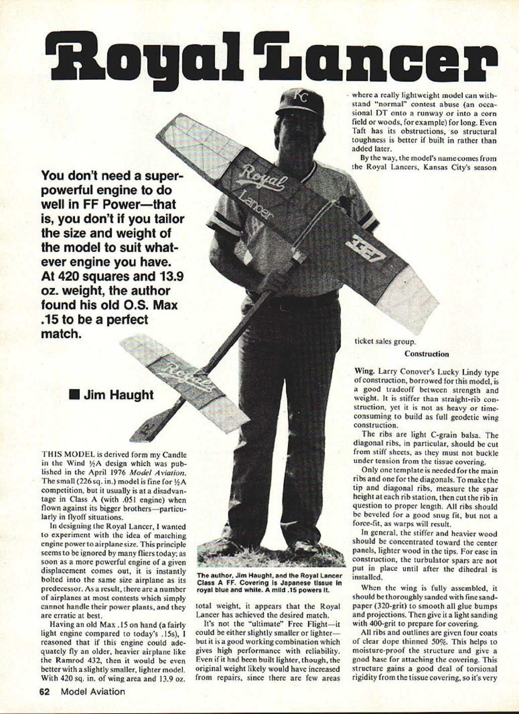
You don't need a super-powerful engine to do well in FF Power—that is, you don't if you tailor the size and weight of the model to suit whatever engine you have. At 420 sq. in. and 13.9 oz. weight, the author found his old O.S. Max .15 to be a perfect match.
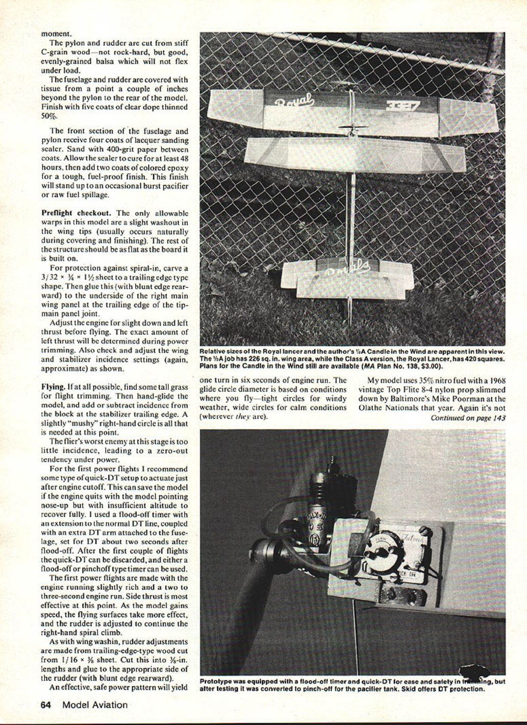
This model is derived from my Candle in the Wind 1/4A design which was published in the April 1976 Model Aviation. The small (226 sq. in.) model is fine for 1/4A competition, but it usually is at a disadvantage in Class A (with .051 engine) when flown against its bigger brothers—particularly in flyoff situations.
In designing the Royal Lancer, I wanted to experiment with the idea of matching engine power to airplane size. This principle seems to be ignored by many fliers today; as soon as a more powerful engine of a given displacement comes out, it is instantly bolted into the same size airplane as its predecessor. As a result, there are a number of airplanes at most contests which simply cannot handle their power plants, and they are erratic at best.
Having an old Max .15 on hand (a fairly light engine compared to today's .15s), I reasoned that if this engine could adequately fly an older, heavier airplane like the Ramrod .432, then it would be even better with a slightly smaller, lighter model. With 420 sq. in. of wing area and 13.9 oz. total weight, it appears that the Royal Lancer has achieved the desired match.
It's not the "ultimate" Free Flight—it could be either slightly smaller or lighter—but it is a good working combination which gives high performance with reliability. Even if it had been built lighter, though, the original weight likely would have increased from repairs, since there are few areas where a really lightweight model can withstand "normal" contest abuse (an occasional DT onto a runway or into a corn field or woods, for example) for long. Even Taft has its obstructions, so structural toughness is better if built in rather than added later.
By the way, the model's name comes from the Royal Lancers, Kansas City's season ticket sales group.
Construction
Wing
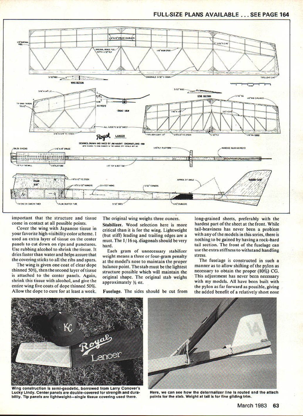
Larry Conover's Lucky Lindy type of construction, borrowed for this model, is a good tradeoff between strength and weight. It is stiffer than straight-rib construction, yet it is not as heavy or time-consuming to build as full geodetic wing construction.
The ribs are light C-grain balsa. The diagonal ribs, in particular, should be cut from stiff sheets, as they must not buckle under tension from the tissue covering.
Only one template is needed for the main ribs and one for the diagonals. To make the tip and diagonal ribs, measure the spar height at each rib station, then cut the rib in question to proper length. All ribs should be beveled for a good snug fit, but not a force-fit, as warps will result.
In general, the stiffer and heavier wood should be concentrated toward the center panels, lighter wood in the tips. For ease in construction, the turbulator spars are not put in place until after the dihedral is installed.
When the wing is fully assembled, it should be thoroughly sanded with fine sandpaper (320-grit) to smooth all glue bumps and projections. Then give it a light sanding with 400-grit to prepare for covering.
All ribs and outlines are given four coats of clear dope thinned 50%. This helps to moisture-proof the structure and give a good base for attaching the covering. This structure gains a good deal of torsional rigidity from the tissue covering, so it's very important that the structure and tissue come in contact at all possible points.
Cover the wing with Japanese tissue in your favorite high-visibility color scheme. I used an extra layer of tissue on the center panels to cut down on rips and punctures. Use rubbing alcohol to shrink the tissue. It dries faster than water and helps assure that the covering sticks to all the ribs and spars.
The wing is given one coat of clear dope thinned 50%, then the second layer of tissue is attached to the center panels. Again, shrink this tissue with alcohol, and give the entire wing five coats of dope thinned 50%. Allow the dope to cure for at least a week.
The original wing weighs three ounces.
Stabilizer
Wood selection here is more critical than it is for the wing. Lightweight (but stiff) leading and trailing edges are a must. The 1/16 sq. diagonals should be very hard.
Each gram of unnecessary stabilizer weight means a three- or four-gram penalty at the model's nose to maintain the proper balance point. The stab must be the lightest structure possible which will maintain the original shape. The original stab weighs approximately 3/8 oz.
Fuselage
The sides should be cut from long-grained sheets, preferably with the hardest part of the sheet at the front. While tail-heaviness has never been a problem with any of the models in this series, there is nothing to be gained by having a rock-hard tail section. The front of the fuselage can use the extra stiffness to withstand handling stress.
The fuselage is constructed in such a manner as to allow shifting of the pylon as necessary to obtain the proper (80%) CG. This adjustment has never been necessary with my models. All have been built with the pylon as far forward as possible, giving the added benefit of a relatively short nose moment.
The pylon and rudder are cut from stiff C-grain wood—not rock-hard, but good, evenly-grained balsa which will not flex under load.
The fuselage and rudder are covered with tissue from a point a couple of inches beyond the pylon to the rear of the model. Finish with five coats of clear dope thinned 50%.
The front section of the fuselage and pylon receive four coats of lacquer sanding sealer. Sand with 400-grit paper between coats. Allow the sealer to cure for at least 48 hours, then add two coats of colored epoxy for a tough, fuel-proof finish. This finish will stand up to occasional bursts or raw fuel spillage.
Preflight checkout
The only allowable warps in this model are a slight washout in the wing tips (usually occurs naturally during covering and finishing). The rest of the structure should be as flat as the board it is built on.
For protection against spiral-in, carve a 3/32 x 3/4 x 1-1/2 in. sheet to a trailing-edge type shape. Then glue this (with blunt edge rearward) to the underside of the right main wing panel at the trailing edge of the tip-main panel joint.
Adjust the engine for slight down and left thrust before flying. The exact amount of left thrust will be determined during power trimming. Also check and adjust the wing and stabilizer incidence settings (again, approximate) as shown.
Flying
If at all possible, find some tall grass for flight trimming. Then hand-glide the model, and add or subtract incidence from the block at the stabilizer trailing edge. A slightly "mushy" right-hand circle is all that is needed at this point.
The flier's worst enemy at this stage is too little incidence, leading to a zero-out tendency under power.
For the first power flights I recommend some type of quick-DT setup to actuate just after engine cutoff. This can save the model if the engine quits with the model pointing nose-up but with insufficient altitude to recover fully. I used a flood-off timer with an extension to the normal DT line, coupled with an extra DT arm attached to the fuselage, set for DT about two seconds after flood-off. After the first couple of flights the quick-DT can be discarded, and either a flood-off or pinchoff type timer can be used.
The first power flights are made with the engine running slightly rich and a two- to three-second engine run. Side thrust is most effective at this point. As the model gains speed, the flying surfaces take more effect, and the rudder is adjusted to continue the right-hand spiral climb.
As with wing washin, rudder adjustments are made from trailing-edge-type wood cut from 1/16 x 3/8 sheet. Cut this into 3/8-in. lengths and glue to the appropriate side of the rudder (with blunt edge rearward).
An effective, safe power pattern will yield one turn in six seconds of engine run. The glide circle diameter is based on conditions where you fly—tight circles for windy weather, wide circles for calm conditions.
My model uses 35% nitro fuel with a 1968-vintage Top Flite 8-4 nylon prop slimmed down by Baltimore's Mike Poorman at the Olathe Nationals that year. Again, it's not the hottest fuel or newest prop, but it's a good working combination.
The original model weighs 13.9 ounces ready to fly. It could easily be built lighter, but it wouldn't be worth the effort. I doubt if the trim would be as consistent, and it would make the model fast enough to be potentially dangerous—it's plenty fast enough as it is.
The exact number of turns in the climb or the diameter of the glide circle is not nearly as important as establishing a trim which is consistent and one you are comfortable in using. It's important for both the model and the flier to be able to repeat their performances time after time. A model trimmed too close to its performance limits will almost never win, because if the smallest error is made, disaster will strike. That's simply not a gamble worth taking.
Practice with the model until you are sure what it will and can do. Then you're ready to be a consistent winner.
Transcribed from original scans by AI. Minor OCR errors may remain.

