


Rudderbug Days in the UK
Trevor Waters
Early Radio Control in Great Britain
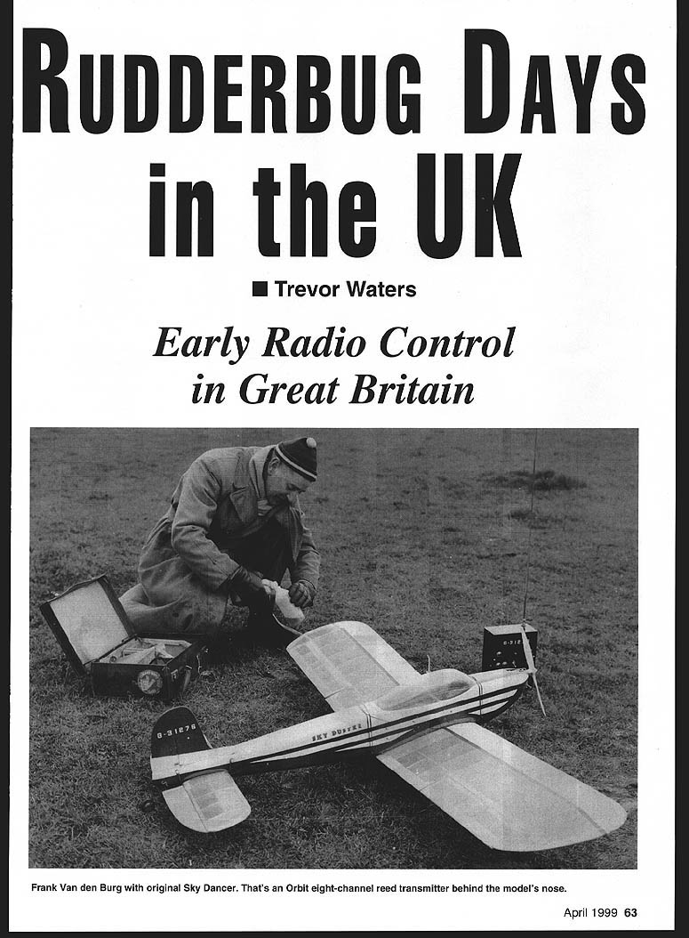
Reading your article on the Rudder Bug ("Super Bug," March 1998 issue) took my mind back more than 40 years to when I built my first radio-control model. Mine was built to the original Walt Good plan and was powered by a Frog 500 5 cc glow engine.
The radio system had a hand-held valve transmitter with a single pushbutton for control, and an ECC95 1B single-valve receiver operating a rubber-powered escapement for rudder only.
The receiver was very touchy to set up. It had two dust-iron-cored slugs (variable inductors) that needed trimming with a small non-metallic screwdriver on each trip to the flying field. An assistant would walk away with the transmitter, operating the pushbutton. Left–centre–right–centre would go the escapement, and the slugs would get twiddled until an acceptable range was achieved.
There was also a variable resistor (potentiometer) in series with the receiver high-tension supply. This was used to adjust the relay so that it switched at the optimum current to achieve the most reliable operation, given the small change in anode current taken by the valve in the receiver between when the transmitter was on and when it was off. A milliamp meter was plugged into the side of the fuselage to allow this to be done. After the adjustments had been completed, the meter was unplugged and a shorting plug was inserted in its place.
The receiver used a 67.5-volt high-tension battery, a 1.5-volt low-tension battery to power the valve filament, plus a 4.5-volt battery for the escapement. They were all primary batteries; small rechargeable batteries were still in the future then.
Not only was the radio difficult to set up and unreliable, the rubber-driven escapement was also a problem. It would usually work reasonably well before the engine was started, but the rubber would then completely or partially unwind as the detent bounced past the stops because of the vibration.
Early RC Flying
The single-valve receiver used in my Rudder Bug was a superregenerative detector. This type of receiver had poor selectivity, and it was only possible for one model to be flown at a time. This did not matter much with the reliability of most equipment at the time. Everybody else would be happy to watch the brave flier have a go; the rest of the modellers present would cluster around the trunk of the car as the model appeared to be seriously being prepared for flight.
Problems to deal with took little effort; the basic free-flight designs were the norm in the early days. Larger sport-type free-flight models with generous wing area and high-lift-coefficient wing sections were considered desirable because they allowed heavy radio equipment to be pulled around the sky by low-powered engines. The problem with using models designed for free flight as radio-control machines was wind penetration—anything more than a gentle breeze turned the flight into a constant battle to stop the model being lost downwind.
Simple bang-bang escapements giving sequential left–centre–right–centre made it difficult to fly smoothly; with no throttle or elevator control the pilot felt powerless to prevent the model climbing continuously, sometimes until almost out of sight. The concentration required caused pilots sometimes to fold under stress and the model would turn away downwind; the distance lost in a complete 360° turn was often too great to allow recovery. Panic was common—seeing the flier running downwind hopelessly trying to regain control, praying that the model would run out of fuel and land. Carrying early ground-based transmitters over hedges and fences took much of the joy out of the hobby.
Now we can make anything from ultra-small indoor RC models up to 45% Extra 300s and huge four-engine B-29s; we can choose among helicopters, electric models, ducted fans and real turbojets. It is worth remembering that in the early days the type of aircraft was basically a free-flight model and the pilot attempted to influence its flight direction as best he could.
Tuned Reed Flying
Early multichannel equipment using tuned reeds was available. It was common to see a flier running downwind, hopelessly trying to regain control of a model or praying that it would run out of fuel in time to see where it landed.
ED sold a three-reed set that could be used to select left and right rudder, plus a sequential engine control. Later they brought out a six-reed set. The receiver of this equipment used three valves for RF detector, audio amplifier, and reed-bank driver. The transmitter was built inside a box of about one cubic foot with an eight-foot-long antenna. It had a very large and heavy 120-volt battery inside called an Everready Winner, plus a 1.5-volt battery for the valve filaments. This unit stood on the ground and a separate control box with a connecting cable was used.
Much of the equipment in use at this time was homemade, and some knowledge of electronics was essential for success. I produced my own tuned-reed system using the ED circuitry. When Howard Bonner came to Woburn Abbey to demonstrate his Smog Hog, it was a shock and a source of inspiration to see outside loops and rolls being performed by a radio-control model.
Later, when the equipment became available in the UK, Smog Hogs and Astro Hogs appeared on the scene being flown in much the same way. However, this style of flying was only really available to those with plenty of spare money, as the cost of such equipment was, in real terms, similar to that of a turbojet engine today.
Rudder-only flying remained the only practical option for many others. The original Orbit radio-control equipment used an eight-channel reed bank with a miniature relay on each channel to operate rudder, elevator, ailerons and throttle.
For aerobatics it was considered best to trim the model so that if left alone it would enter a steepening dive until impact with the ground. In operation the pilot would have to continually blip up elevator to prevent this; when flying inverted, down elevator would be blipped. This setup could be tricky on early flights until the model had been trimmed, particularly if it had to be continually corrected in roll at the same time.
Later equipment had ten-reed banks, with the extra two channels being used to operate a separate elevator-trim servo, which enabled the model to be trimmed for level flight.
Another refinement was the introduction of "simultaneous control" with twin oscillators in the transmitter, the outputs of which could be mixed to allow certain combinations of two controls (for example, aileron and elevator) to be selected at the same time.
The combination of a well-prepared model and a good pilot using this type of equipment produced performance that would not look out of place on a flying field today. Top pilots could blip the controls at a speed that produced almost proportional control. This blipping can become a fetish, and sometimes unnecessary corrections could be observed. Indeed, the instinct became so strong in many ex-reed fliers that they continued to blip after they had changed to proportional equipment.
Servos
Rubber-driven escapements could operate a rudder on a good day, but lacked the power to operate elevators. Early motorised servos tended to be unreliable. For a time George Honnest-Redlich and Sid Allen, who were leading the pack in the UK around 1955, favoured an actuator using twin solenoids operating a bellcrank for rudder control. This actuator was preferred for its simplicity and reliability.
Control of other functions remained a problem until the Bonner servos became available. The most widely used type was the Duramite. The first versions interfaced with relays in the receiver, but later types called Transmitters included drive circuitry using early transistors, and interfaced directly with the reed bank, dispensing with the need for relays in the receiver.
Because of the cost of commercial equipment in the UK, some modellers made their own servos. I sometimes used a simple actuator based on a Mighty Midget motor and a rubber band for centring. This provided crude proportional control if the direction of current through it was continuously and quickly reversed with a varying mark-to-space ratio.
Some experimenters invented all sorts of strange devices involving rotating cotton reels with specially shaped copper covering and a contact moved by the control stick. The famous "galloping ghost" was a development of this, which also provided effective elevator control by variation of pulse rate.
Engines
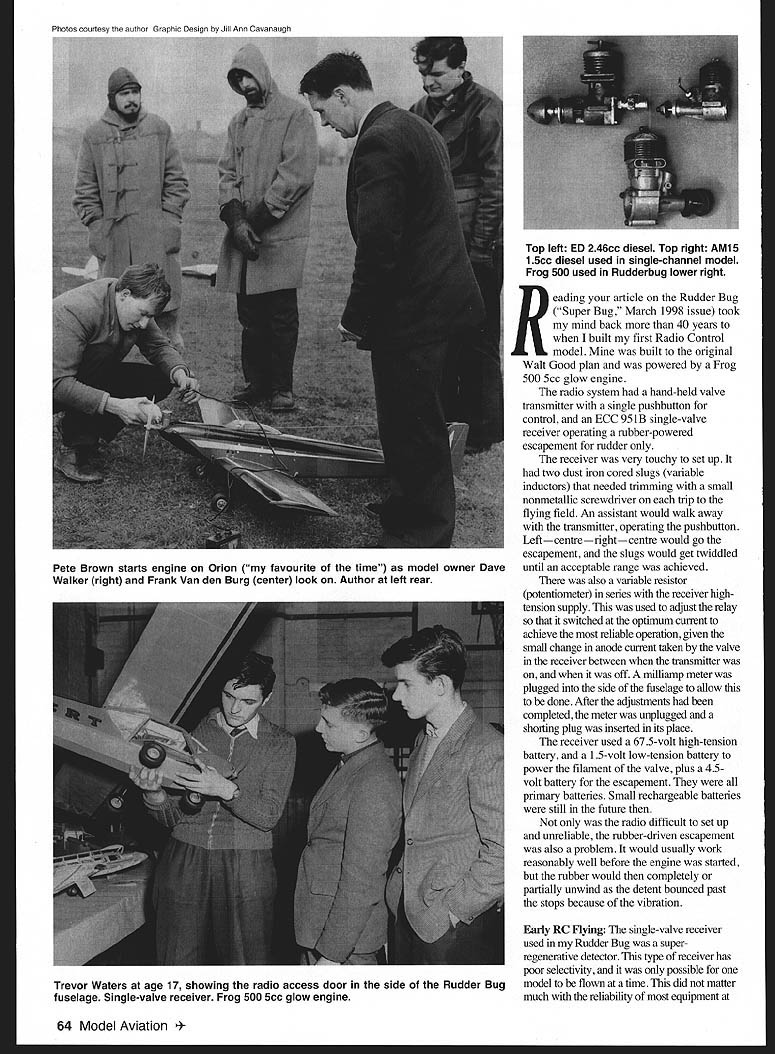
There were severe constraints on the choice of engines available in the early days. Although there were the Dooling .61 and McCoy .60, these had no throttle control and were mainly used for control-line speed. Radio-control modellers in the UK usually settled for less ambitious, tamer power plants. The ED Hunter 3.46 cc diesel was a favourite—no silencer, but much easier to handle and with an acceptable noise output.
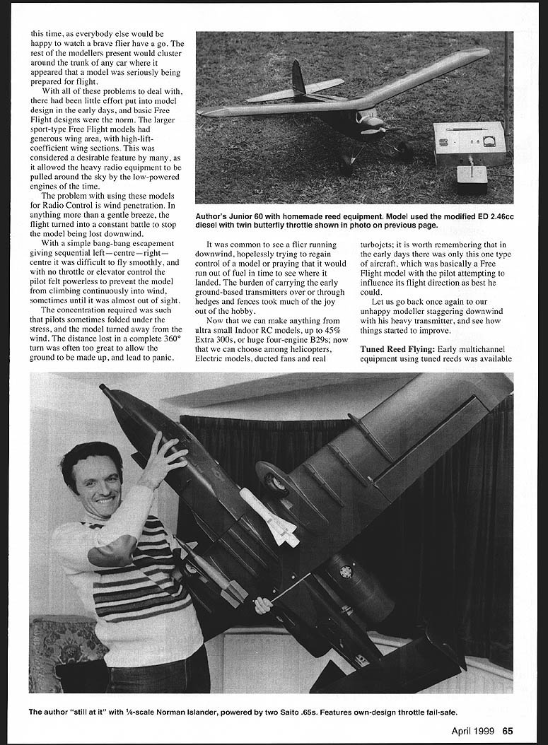
At first, it was difficult to obtain engines fitted with a means of controlling power output. When they began to appear, some used a choke and others had an exhaust restrictor. It was possible to get ED engines modified with a twin butterfly valve that was sufficiently free in operation to be operated by a rubber-driven escapement if required. I still have an ED 2.46 diesel which was fitted this way and was in the Junior 60. The trouble with this engine was that after a long tickover it would miss badly when the throttle was opened until it heated up. It was only when glow-plug engines fitted with barrel carburettors became available that proper control was obtained.
Model Design
High-camber wing sections suffer from considerable rearward movement of the centre of pressure with increasing speed. To avoid the risk of the tailplane losing control as speed builds up in a dive, and the model tucking under, a powerful tailplane stabilising downforce, combined with a forward centre of gravity, is called for. The original Rudder Bug had the tailplane set at approximately -3/8°. With this setup the model is basically single-speed, with the downforce on the tail balancing the nose-down pitching moment caused by the forward centre of gravity.
The limited power available from engines of the time resulted in a reasonable angle of climb under power and a very good glide after the engine cut. Given a calm day, plus reliable rudder and throttle control, such a model would provide wonderful, relaxed flying today.
The advantage of having proportional elevator control is probably difficult to appreciate by those who have not had to make do without it. If the original Rudder Bug was made today with a typical .40-size engine running at full throttle, the rate of climb would be such that the model would be almost unmanageable with rudder-only control. Throttle control would turn it into a perfectly acceptable model in calm conditions, and fully proportional elevator control would allow some penetration on windy days.
Proportional elevator control was not an option in the early days. Bang-bang elevator control was of little use; the model would simply bounce up into a climb after down elevator had been returned to neutral. Elevator trim was found to be much better, but this required reed equipment with a leadscrew servo.
Some single-channel users tried another escapement, activated when the rudder escapement paused at one of the two neutral positions. (When not required, the rudder escapement could be slipped past it to the other neutral position.) This method of control was hopeless with a self-centring elevator, but could be used to select a fixed elevator-trim position for flying into wind.
To allow models to penetrate wind better, wing sections with much lower camber were adopted. This allowed the centre of gravity to be moved back and the longitudinal dihedral to be reduced, because of the reduced change in centre-of-lift position. This needed to be done carefully in small stages; with no proper elevator control the possible consequences could be disastrous. Given care, however, a much more exciting model could be achieved that would climb steadily in a straight line but could be made to fly level in a wide turn or dive and pick up speed in a tighter turn. With practice this could result in a fast, sweeping flyby, even on rudder-only.
I designed a rudder-only model with a simple proportional servo based on a layout suggested by Harold de Bolt (Aeromodeller Annual 1954–55). It had a four-foot wingspan, semi-symmetrical wing, symmetrical tailplane and lightweight open structure. It was powered by an AM15, a British 1.5 cc diesel.
Model design for the later generation of reed equipment moved rapidly toward what is in use today. Many modern designs use veneer-covered foam wings and either a fibreglass fuselage or one with large areas of fairly thick sheeting, often reinforced with plywood. I am sometimes staggered by how heavy some models are. There is no need for all this "beefing up." Models should be designed to fly, not to crash.
I recently built a Chris Olsen Uproar (designed in 1961) and fitted it with modern equipment and an O.S. .46 engine. This model featured fully symmetrical wing and tailplane surfaces, with built-up open structure and nylon covering. Total weight was 5 lb 3 oz, with a wing loading of 15.5 oz/ft².
Many of the older designs are of similar construction and would make fine models today with modern engines and equipment. I still see kits for the Astro Hog advertised; my favourite of the time was the Orion.
Radio Control
The greatest changes in radio-control equipment came about as a result of the invention of the transistor.
Early transistors had unity gain at around 1 MHz, so they could not be used in the RF stages. This brought about the "transistorised receiver" that still used a valve as a superregenerative detector, but had transistors to amplify the audio-tone modulation used to switch the relay. This design provided a huge increase in reliability compared with the earlier single-valve receivers, and there was no longer any requirement to fine-tune the "quench" at the field.
The same basic design could also be used to drive a reed bank. A 22.5-volt "high-tension" battery could be used with this type of receiver, instead of 45 volts or 67.5 volts. When transistors were available that could produce useful gain at 27 MHz, receivers could be operated at five to nine volts.
The cost of good-quality reed equipment, and the limitations of single-channel radio using escapements, led many modellers to experiment with their own equipment. I never liked escapements, and, as mentioned, changed to an electric motor with a single-stage gear (known as a Mighty Midget). The gear was forced to a central position by a rubber band, and the supply voltage switched from one direction to the other by the receiver relay output to provide full left and right.
Blipping the switch would produce a primitive form of proportional control if the mark-to-space ratio was changed. This blipping could be done by hand using a microswitch, but transistor multivibrator circuits could provide this automatically from a control knob.
Proportional Control
Even when reeds were at the height of their popularity, many realised that fully proportional control was the ultimate goal. Crude systems like those discussed above had been used by experimenters for one or two channels, but the development of a full-house proportional outfit took a long time. They were usually based on independent variation of frequency and mark/space ratio.
Walt Good had a design of this type in the early days. The servos were based on balancing a voltage input with a voltage derived from a position-feedback pot. It was difficult to provide sufficient filtering to the receiver outputs to achieve a smooth DC control voltage without slugging the response time excessively. They also suffered from unwanted thrashing at "switch on."
A major breakthrough was the idea of using a servo that produced a pulse of one to two milliseconds duration in response to a pulse of similar duration from the receiver. The servo would then strive to cancel any difference between the two pulse widths. This system had the advantage that the servo would not attempt to move until it received a pulse, so it behaved itself at "switch on" and provided fast response when called for.
It greatly simplified the receiver design, as all that was needed in the way of decoding was a simple shift register to sort out the time-multiplexed pulses onto their correct outputs, and a frame detector for reset. Shift registers in integrated-circuit form became available at about the right time as a spinoff from defence investment by the US government.
The only problem was packaging the far-from-trivial amount of electronics into very small aircraft size. Some manufacturers solved this by putting the electronics for all servos inside the receiver. This resulted in a very large receiver, and the ultimate solution was to employ a custom-built integrated circuit inside each servo.
In the UK, Skyleader used a 2N409 chip made by Ferranti, which solved the problem. In England it was probably the Futaba M Series that first brought radio control to the masses, and market winners and club membership grew as more people were able to take part in the hobby.
Apart from the obvious advantage of not having to blip the controls anymore, proportional control provided a huge bonus in that models could now be trimmed in flight by using trim levers on the control sticks. These are now taken for granted, but previously we were confined to mechanical adjustment at the control surfaces (unless an extra servo was used for elevator trim) and had to land each time to make a change.
Type of Modulation and the Dreaded Glitch
All old equipment used amplitude modulation (AM). This method detects changes in signal amplitude that are intended to contain only the information of interest. In reality, the demodulated signal can include signals from other users of the frequency, noise, or multipath interference.
Multipath interference is caused when the transmitted signal bounces off an object and arrives at the receiver some time after the direct-path signal. The effect depends on the relative phase of the two signals and can either increase or decrease the signal amplitude. As the model moves, the conditions change and this reinforcement-and-cancellation process becomes cyclic, producing a signal that interferes with the true one. The effect depends on the relative amplitude of the interference and the threshold set at the input to the decoder. Many of the crashes from so-called glitches at the time (those that were not really excuses for pilot error) were probably caused by multipath interference.
With frequency modulation (FM), the received signal is clamped in level at the receiver, which recovers the original signal from the systematic changes in frequency introduced by the transmitter. Multipathing has little effect on this type of equipment; amplitude changes are lost in the amplitude-clamping process.
Interference from other users of the frequency (like a flier from a nearby club) doesn't have as much effect on FM equipment. FM receivers effectively grab the strongest signal and ignore others. It has been shown that an FM receiver will pay no attention to interference, provided the power level of the interferer is no more than approximately one quarter that of the proper signal.
Conclusion
After reading all this, you may be surprised to learn that I am still flying radio-control models today. The advances that have been made are truly staggering. Although I cannot claim to have been there from the very beginning of radio control, I have seen all the important changes since around 1955 and have found it fascinating to observe, and to some extent to take part in, the progress.
Trevor Waters 6 Crescent Drive Petts Wood Kent BR5 1BD United Kingdom
Transcribed from original scans by AI. Minor OCR errors may remain.

