
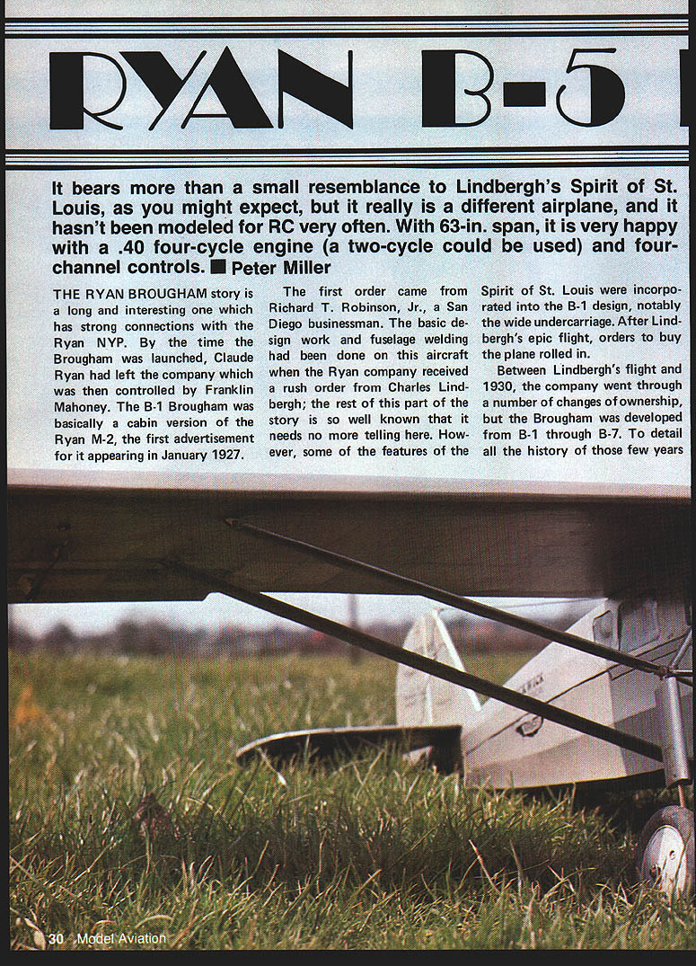
Ryan B-5 Brougham
It bears more than a small resemblance to Lindbergh's Spirit of St. Louis, as you might expect, but it really is a different airplane, and it hasn't been modeled for RC very often. With a 63‑in. span, it is very happy with a .40 four‑cycle engine (a two‑cycle could be used) and four‑channel controls. — Peter Miller
History
The Ryan Brougham story is a long and interesting one with strong connections to the Ryan NYP. By the time the Brougham was launched, Claude Ryan had left the company, which was then controlled by Franklin Mahoney. The B‑1 Brougham was essentially a cabin version of the Ryan M‑2, the first advertisement for it appearing in January 1927.
The first order came from Richard T. Robinson, Jr., a San Diego businessman. Basic design work and fuselage welding had been done on this aircraft when the Ryan company received a rush order from Charles Lindbergh; the rest of that part of the story is well known. Some features of the Spirit of St. Louis were incorporated into the B‑1 design, notably the wide undercarriage. After Lindbergh’s epic flight, orders rolled in.
Between Lindbergh's flight and 1930 the company went through several ownership changes, but the Brougham was developed from B‑1 through B‑7. Records were broken and outstanding flights were made during those years.
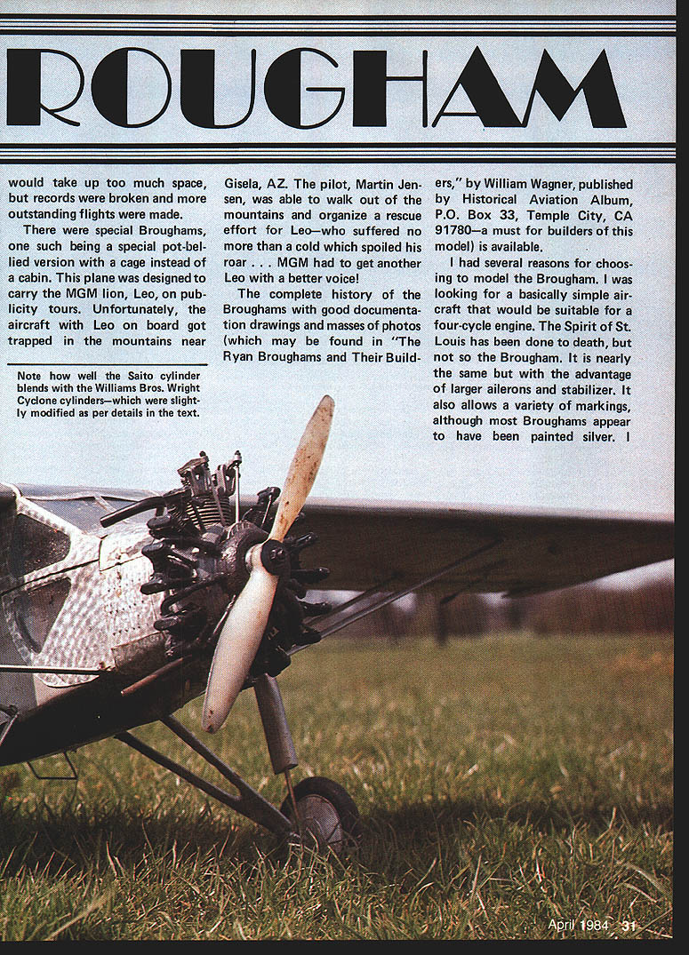
There were special Broughams as well. One pot‑bellied version carried the MGM lion, Leo, on publicity tours. That aircraft became trapped in the mountains near Gisela, AZ; the pilot, Martin Jensen, walked out to organize a rescue for Leo, who suffered no more than a cold that spoiled his roar. MGM had to get another Leo with a better voice.
For detailed history, documentation, drawings, and many photos, see The Ryan Broughams and Their Builders, by William Wagner (Historical Aviation Album, P.O. Box 33, Temple City, CA 91780) — a must for builders of this model.
Why model the Brougham
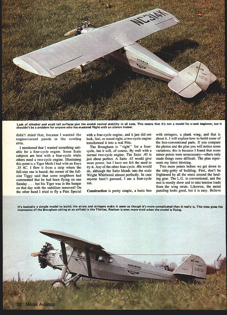
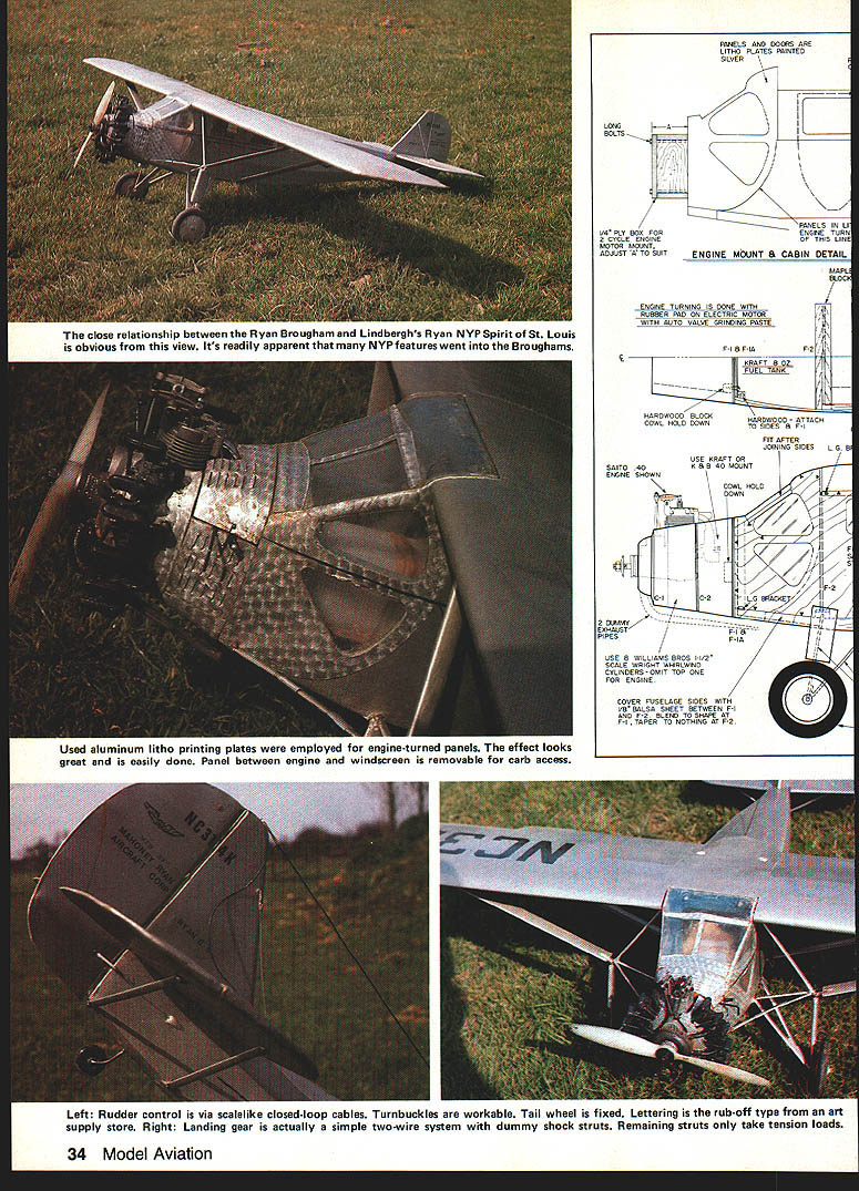
I chose the Brougham because I wanted a basically simple aircraft suitable for a four‑cycle engine. The Spirit of St. Louis has been modeled many times, but the Brougham has not. It is nearly the same but with the advantage of larger ailerons and stabilizer, and it allows a variety of markings (most Broughams appear to have been painted silver). I wanted engine‑turned panels in the cowling area and something that suited a four‑cycle engine.
Some scale subjects suit a four‑cycle engine; others need a two‑cycle. For example, my Tiger Moth with an Enya .35 4C sounded and felt right for its subject; a Pitts Special did not feel or sound right with a four‑cycle and was transformed by a two‑cycle. The Brougham is right for a four‑cycle but will also fly well on a normal two‑cycle.
The Saito .40 is about perfect for this scale; the Saito .45 would give extra power, though I never felt the need to try it. Any other four‑cycle .40 would do; the Saito blends the scale Wright Whirlwind nearly perfectly. In case it wasn't already clear—I'm a four‑cycle enthusiast.
Construction overview
Construction is straightforward: a basic box fuselage, stringers and a plank wing. I will explain a few less‑conventional parts and compare photos. The plan may show minor variations because I found some details unnecessary and others difficult; the plan represents my latest thinking.
Two points before building:
- Don't be frightened by all the struts around the landing gear. The landing gear is conventional; most of the extra struts take tension loads from the wing struts and are largely for appearance.
- Metal paneling looks good and is not difficult to do.
Build the struts and stringers as shown. Though it may seem complicated at first, the finished model gives the unmistakable impression of a Brougham sitting on a Thirties airfield. Realism is vivid both in appearance and in flight.
Fuselage
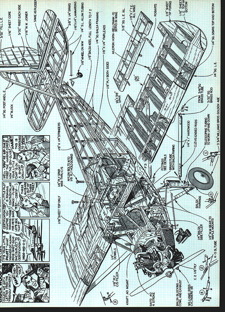
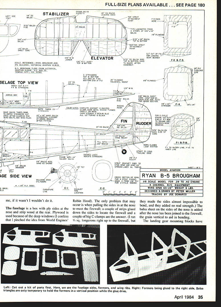
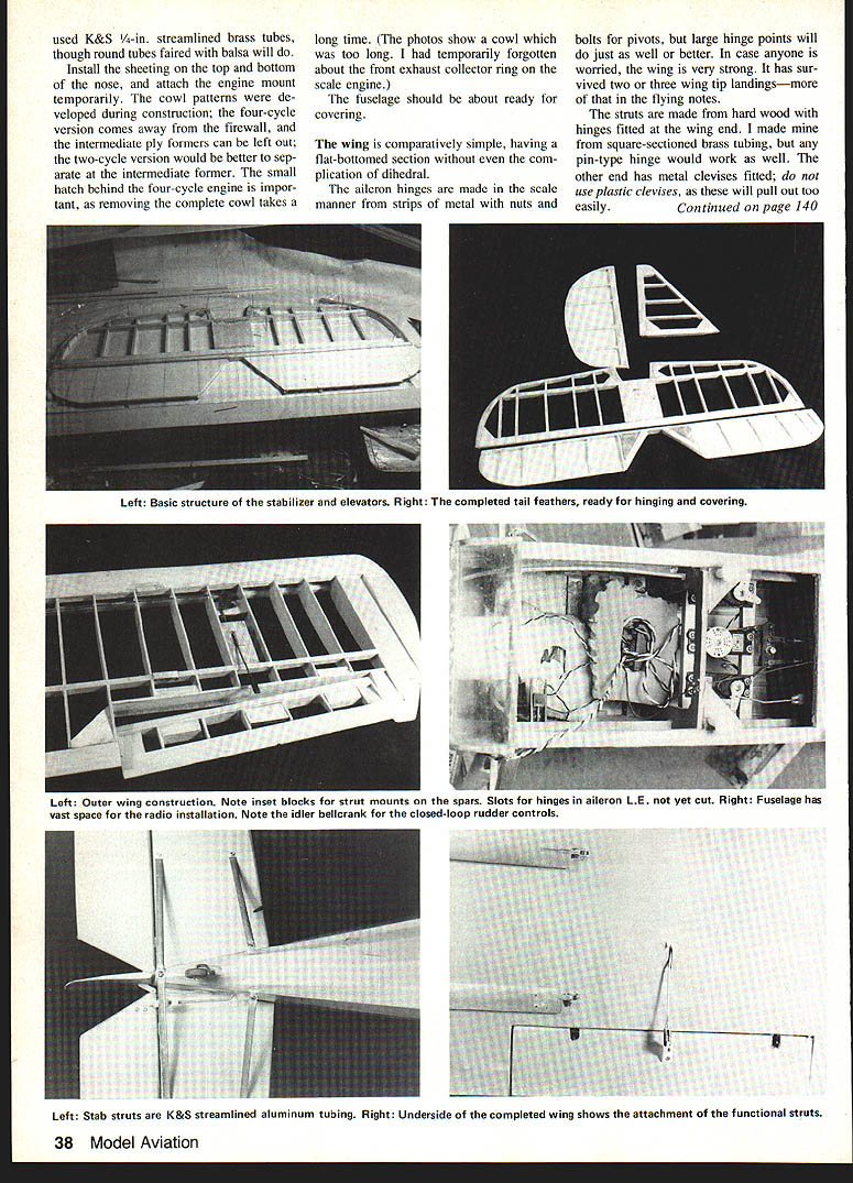
The fuselage is a box with plywood sides at the nose and strip wood at the rear. Plywood is used at the nose because of the deep windows. The only tricky part is pulling the sides in at the nose to meet the firewall; a couple of strips glued down the sides to locate the firewall and a couple of big C‑clamps are the answer. I ran 3/4‑in. longerons right up to the firewall at first, but they made the sides almost impossible to bend and added no real strength, so I did not use them in the final layout.
Balsa sheeting on the sides of the nose is added after the nose has been joined to the firewall, with the grain vertical to aid bending. Fit the rear strut bracket mounting blocks at this time.
Install the stringers:
- Bottom stringers contact the fuselage cross members.
- Side stringers are glued to the uprights.
- Top stringers are clear of the cross members.
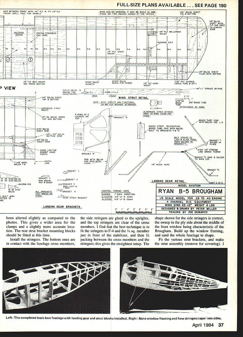
I find the best technique is to fit the stringers to F‑4 and the 1/4‑in. square member just in front of the stabilizer, then pack between cross members and stringers to get the straightest setup. The sweep in the ply side about the middle of the front window is characteristic of the Brougham. Build the window framing and sand the whole fuselage to shape.
Fit the various strut brackets and make the strut assembly (remove for covering). I prefinished the struts with a light coat of dope before assembly since it's difficult to reach inside after they are in place.
Nose, engine mount, and cowl
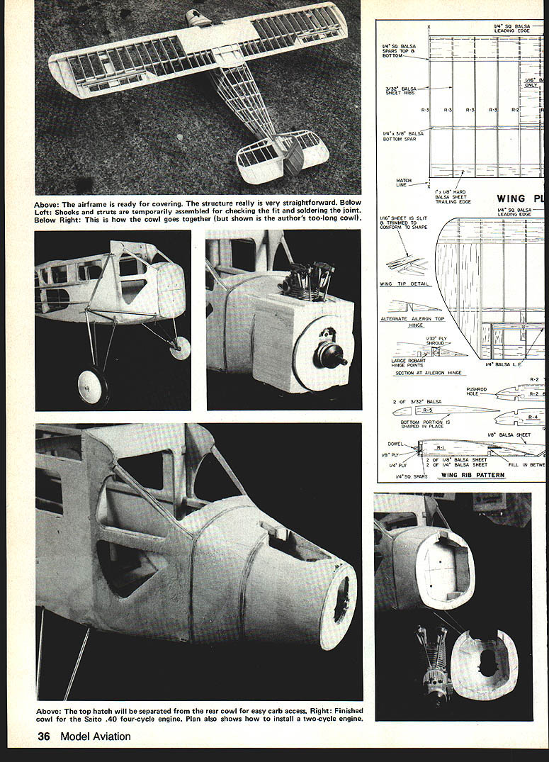
Install the top and bottom sheeting on the nose and attach the engine mount temporarily. The cowl patterns were developed during construction. On the four‑cycle version the cowl comes away from the firewall; intermediate ply formers can be left out. For a two‑cycle version it is better to separate at an intermediate former. Include a small hatch behind the four‑cycle engine—removing the complete cowl takes a long time otherwise. Be mindful of any front exhaust collector ring on scale engines when setting cowl length.
Wing
The wing is comparatively simple, having a flat‑bottomed airfoil without dihedral. The aileron hinges can be made in a scale manner from metal strips with nuts and bolts for pivots; large hinge points will work as well or better. The wing is very strong and has survived several wing‑tip landings.
Struts and landing gear
Struts are made from hard wood with hinges at the wing end. I used square‑section brass tubing for mine, but any pin‑type hinge will work. The other end has metal clevises—do not use plastic clevises, as they will pull out too easily.
The landing gear is straightforward. Use 1/8‑in. music wire for the axles. The brackets are laminated from 1/32‑in. ply and 3/32‑in. balsa. I used K&S 1/4‑in. streamlined brass tubing for some fittings, though round tubes faired with balsa will do. The shock struts are simply two tubes sliding inside one another with a balsa fairing. Tail struts are K&S 1‑1/2‑in. streamlined aluminum tubing. Tail rigging wires are from control‑line wire, and I used two small Pro‑Line turnbuckles.
Tail assembly
The stabilizer and fin are simple and strong, especially when combined with the struts and rigging wires. The rudder and elevators feature a central core of 1/16‑in. sheet—simple, strong, and light. Keep minimum weight at the rear; otherwise many ounces of lead may be required in the nose for balance. With a four‑cycle engine I did not need any nose weight, but lighter two‑cycle engines may require it.
Covering
My model was covered with white Solartex—the best covering material I have used in 30 years of model building. I have not tried Coverite or Fabri‑Kote, but those likely will do. Regular heat‑shrink film is a definite no‑no for the wings at least; it would not look right on the rest of the model. The finished model is sprayed silver from auto touch‑up spray cans with black trim. Rub‑down transfers from an art supply store can be found to match most lettering.
Detail work
Nose panels and engine‑turning
The nose is covered with aluminum litho plate. Used printing plates can often be obtained cheaply from a printer; I got ten 20 x 10‑in. sheets for less than a dollar. The material is 0.010‑in. thick and can be cut with scissors or a sharp knife.
Steps:
- Make paper templates and cut each panel.
- Engine‑turn the panels with a Dremel or small motor fitted with a 1/4‑in. cork or rubber disc and a dab of valve‑grinding paste. Make a row of circles along the rear edge, then another row overlapping and centered between the first row. Continue to the front and wipe clean.
- Cut louvers with a chisel‑shaped knife blade and finish with a screwdriver or shaped hardwood.
- Use litho plate for side window and door panels as well, but paint those rather than turning them.
Attach panels with contact cement. Once adhered, cut holes for the dummy engine cylinders with a sharpened piece of tubing.
The Wright Whirlwind on the B‑5 Brougham had pushrods at the rear and exhaust at the front. The Williams Bros. 1‑1/2‑in. cylinders I used have pushrods at the front and exhaust on the left (looking forward). I left the pushrods at the front to better match the Saito and moved the exhaust pipes to the right side, using stripped wire insulation to connect to the front exhaust collector ring.
Radio installation and equipment
Space is generous in the Brougham. It is possible to add interior detailing and still hide most of the radio gear.
- The fuel tank sits on a platform behind the firewall; the filler screws are behind F‑3 for easy checking.
- The receiver and battery pack sit in lumps of foam rubber between F‑2 and F‑3.
- Controls used: closed‑loop for the rudder (I used them to try them out), a normal pushrod to the elevators, cable‑in‑rod for the throttle, and pushrod‑and‑bellcrank for the ailerons. Be extra careful to avoid any backlash in the aileron run.
Flying
Make sure the model balances as shown on the plan. Adjust control throws to specifications and ensure your engine is reliable. I experienced the Saito cutting on takeoff due to an air leak where the intake manifold enters the cylinder head; this resulted in one or two wing‑tip landings with only minor damage.
The model has near‑neutral stability: it will remain in whatever attitude it is placed. This includes a steady dive regardless of speed, a steady climb until it slows below stalling speed, and any degree of bank. It is very responsive to ailerons and elevator and less so to the rudder; turns fly best with coordinated rudder and aileron.
Takeoffs require up‑elevator until a little speed builds, then be ready to correct swing with the rudder. Setting the wheels slightly inward (toe‑in) reduces the tendency to swing; wheels pointed outward encourage ground loops.
The Brougham is a pleasure to fly—especially a slow fly‑past with a four‑stroke purring at half throttle and then opening up to climb away. It’s about as close to paradise as you can get.
Safety reminder
FLYING NEAR AIRPORTS — BE CAREFUL! PROTECT YOUR RIGHT TO FLY!
Transcribed from original scans by AI. Minor OCR errors may remain.

