
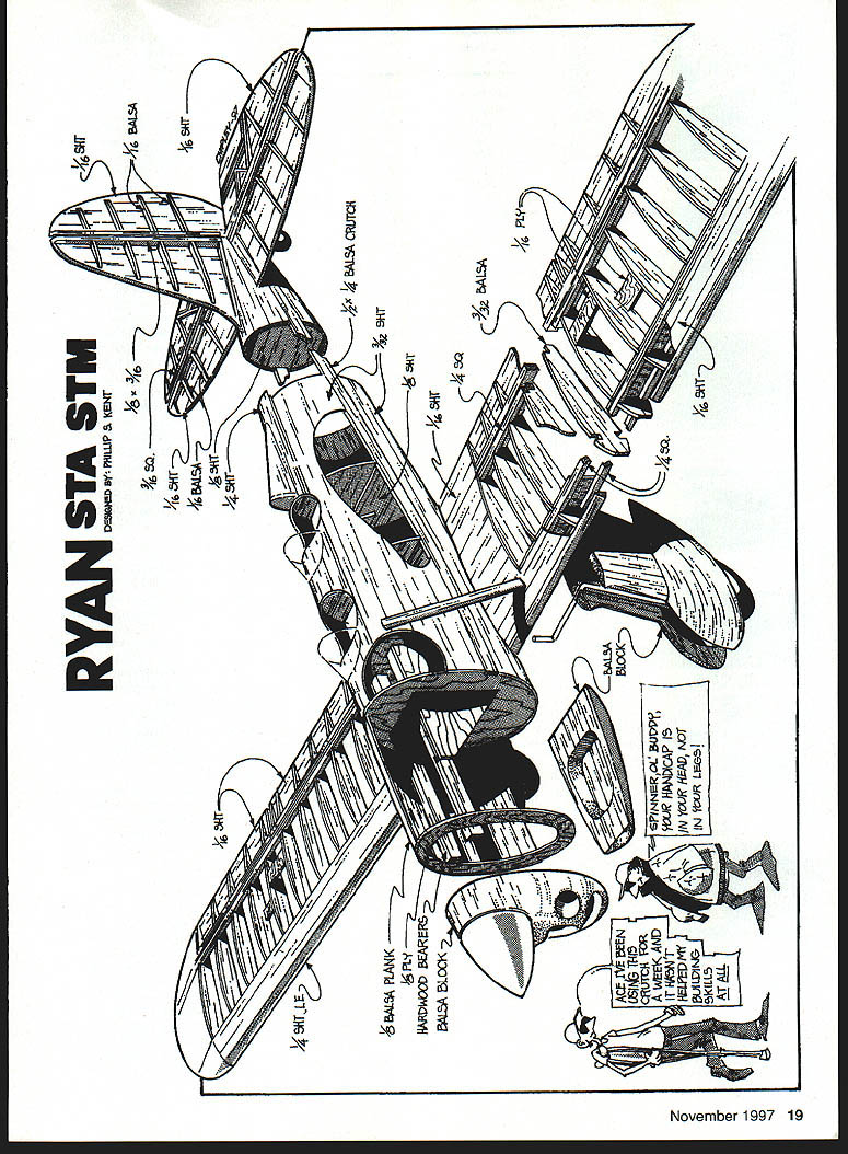
Ryan Sport Trainer
Phillip Kent
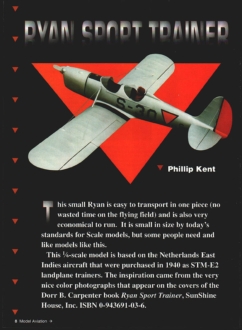
This small Ryan is easy to transport in one piece (no wasted time on the flying field) and is also very economical to run. It is small in size by today's standards for scale models, but some people need and like models like this.
This 1/6-scale model is based on the Netherlands East Indies aircraft that were purchased in 1940 as STM-E2 landplane trainers. The inspiration came from the very nice color photographs that appear on the covers of the Dorr B. Carpenter book Ryan Sport Trainer, SunShine House, Inc., ISBN 0-943691-03-6.
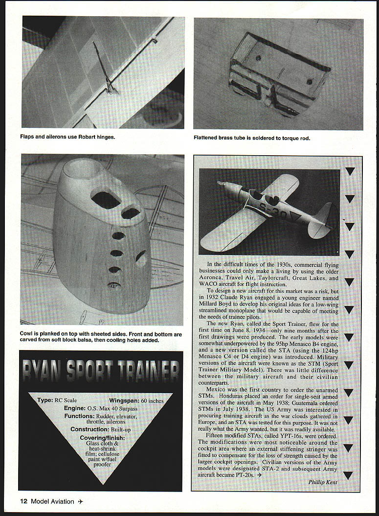
In the difficult times of the 1930s, commercial flying businesses could only make a living by using older Aeronca, Travel Air, Taylorcraft, Great Lakes, and WACO aircraft for flight instruction. To design a new aircraft for this market was a risk, but in 1932 Claude Ryan engaged a young engineer named Millard Boyd to develop his original ideas for a low-wing streamlined monoplane capable of meeting the needs of trainee pilots.
The new Ryan, called the Sport Trainer, flew for the first time on 8 June 1934—only nine months after the first drawings were produced. Early models were somewhat underpowered with the 95 hp Menasco B4 engine, and a new version called the STA (using the 125 hp Menasco C4 or D4 engine) was introduced. Military versions were known as the STM (Sport Trainer Military Model). There was little difference between the military aircraft and their civilian counterparts.
Mexico was the first country to order the unarmed STMs. Honduras ordered single-seat armed versions in May 1938; Guatemala ordered STMs in July 1938. The US Army tested an STA as war clouds gathered in Europe. Fifteen modified STAs, called YPT-16s, were ordered; the most noticeable modifications were around the cockpit area, where an external stiffening stringer compensated for the loss of strength caused by larger cockpit openings. Civilian versions of the Army models were designated STA-2 and subsequent Army aircraft became PT-20s.
Construction
The Ryan ST uses typical model aircraft construction techniques. The materials used are balsa, plywood, and a small amount of hardwood.
Fuselage
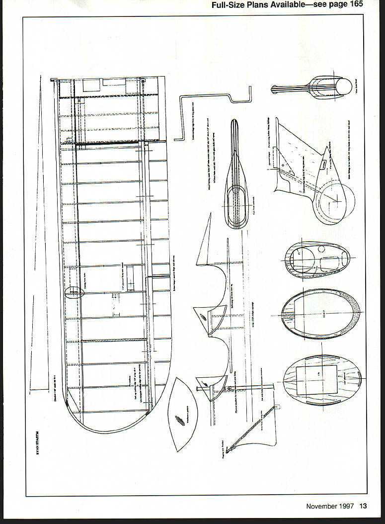
The fuselage uses the crutch method of construction. Pin a 1/2 x 1/4 balsa strip over the plan and fit the cross-pieces. Cement 1/8 square balsa strips to the crutch to support the sheet covering. Add the upper formers next and then the 3/32 sheet balsa capping pieces. Fit the engine bearers and cover the structure with 3/32 sheet balsa.
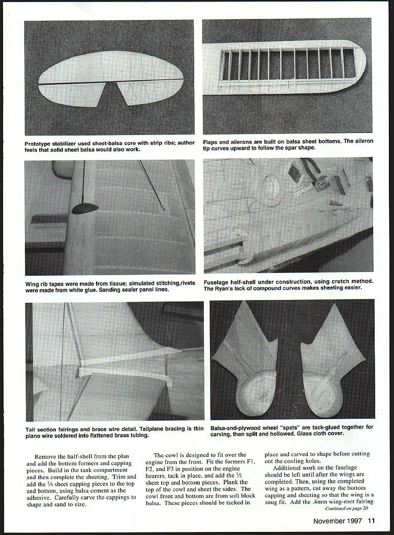
Keep the upper fuselage in place over the plan while fitting the sheeting. Because there are no compound curves, application of the sheeting should present few problems. Wetting the outside with water will help the sheeting bend; use pins to hold it in place until the glue dries.
Remove the half-shell from the plan and add the bottom formers and capping pieces. Build in the tank compartment and then complete the sheeting. Trim and add the 1/4-sheet capping pieces to the top and bottom, using balsa cement as the adhesive. Carefully carve the cappings to shape and sand to size.
The cowl is designed to fit over the engine from the front. Fit formers F1, F2, and F3 in position on the engine bearers, tack in place, and add the 1/2-sheet top and bottom pieces. Plank the top of the cowl and sheet the sides. The cowl front and bottom are from soft block balsa; tack these pieces in place and carve to shape before cutting out the cooling holes.
Additional work on the fuselage should be left until after the wings are completed. Using the completed wing as a pattern, cut away the bottom capping and sheeting so the wing is a snug fit. Add the 4 mm wing-root fairing, base and build up the fairing with soft balsa block. The 1/4-sheet tailplane mount can now be added and the headrest shaped from soft balsa block. Do not fit the headrest until after the fuselage has been covered.
Tail Unit
The tailplane, fin, and rudder were built using the core method of construction. Since the model has a long nose and there was no center-of-gravity problem with the prototype, it is possible to use soft sheet balsa for these components. Sand the units to the correct airfoil sections as shown on the drawing.
There is a large fairing at the bottom of the fin; make this from soft balsa and hollow it out. The rudder horn is made from 1/16 G.R.P. sheet; one side connects to the servo and the other to the steerable tailwheel.
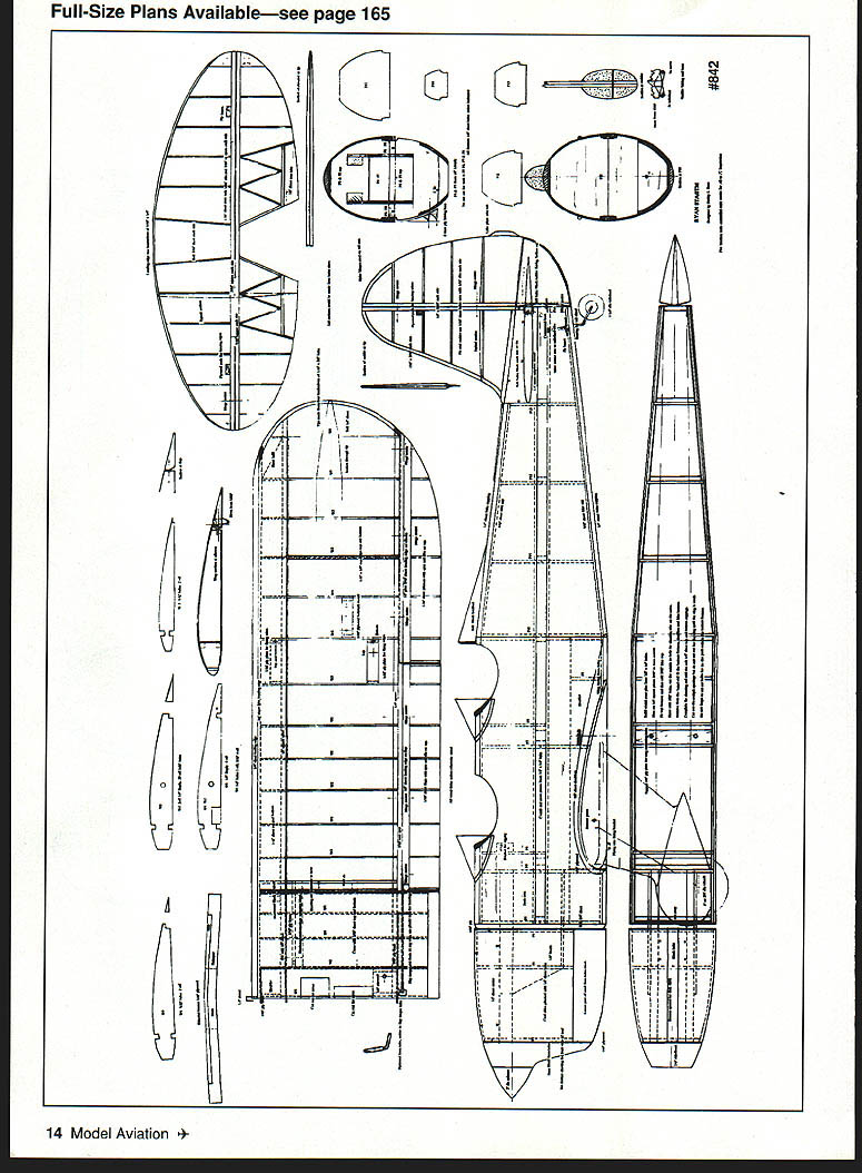
Wing
The wing can be built directly over the plan. Pin the 1/4 square bottom spars, the 3/16 flap/aileron spar, and the center-section trailing edge. Add the ribs and the laminated tip, followed by the top spar and the false leading edge.
The laminated tip is best made around a former, which can be made from plywood cut to the inside tip shape. Cover the face where the strips are to be placed with masking tape to keep them from sticking to the former. Glue four strips of 3/32 x 1/16 balsa together (use white glue) and wrap them around the former. Start at one end, holding the strips in place with masking tape as they are wrapped around. Allow to dry overnight.
Remove the partially built wings from the plan and join the two halves using the plywood braces. This is the time to fit the linkages for the ailerons and flap torque tubes. Fit the undercarriage blocks and then the bottom leading-edge sheeting. Pin the wing back over the plan with a 1/8 piece of packing under the outer rib trailing edge to give some built-in washout.
With the packing still in place, sheet the leading edge and fit the vertical webbing pieces. Carry out the same procedure for the second half. Complete the wing sheeting, add the capstrips, and any support blocks for rigging, etc.
The flaps and ailerons are built on 1/16 sheet bottom. The aileron tip will need to curve upward to follow the spar shape; this can be achieved by firmly stroking the sheet balsa along the grain towards the tip with a piece of round dowel or the handle of a modeling knife.
Undercarriage, Spats, and Tailwheel
Bend the piano wire legs to shape and fit them into the blocks in the wing. The wire can be held in place with a plywood cover or the more normal metal brackets.
The wheel covers or spats are made from balsa and plywood and are built in two halves. Make up the laminated halves as indicated on the drawing and spot-glue them together—two or three spots of glue only, so you can split them back into two pieces later. Carve and sand the covers to shape and cut out for the bracing wire brackets. Split the covers and remove the center portion where the wire leg and plywood stop fit. The plywood stop fitted into the wing controls the rearward travel of the legs. The wheel covers are fastened to this stop and the underside of the wing. There should be ample movement for a spring effect on the undercarriage legs. On the prototype model the wheel covers were covered with lightweight glass cloth before fitting in place.
A steerable tailwheel was fitted to the original model; the bearing was made from brass strip and tube. A flattened brass tube extension was soldered to the top of the axle shaft; it is drilled and connects to a short pushrod from the rudder closed-loop crank.
Finishing
There is considerable rigging on the wings and tail unit. Make sure that all plywood pads to accept these fittings are in place before covering.
The fuselage cowl and wheel covers were covered in lightweight glass cloth using epoxy. This finish is quite easy to apply and does help prevent damage to the balsa surfaces later.
The wings and tail were covered in heat-shrink fabric. Tissue rib tapes were added and simulated rib stitching applied as small blobs of white glue with a pointed piece of 1/16 dowel. Panel lines were scribed on the fuselage, strips of masking tape fitted, and a coat of sanding sealer painted on. When the tape was removed it left a realistic edge to the panels; a final application of white glue rivets completed the illusion.
The prototype was finished in cellulose paint, sprayed on. Use whatever finishing system you are comfortable with. The author’s model was painted in the Dutch East Indies color scheme, but there are many other alternatives—do a little research and decide which aircraft type you are going to model before starting to build.
Scale Model Research, 314 Yukon Ave., Costa Mesa, CA 92626, has a good range of photographs of this aircraft.
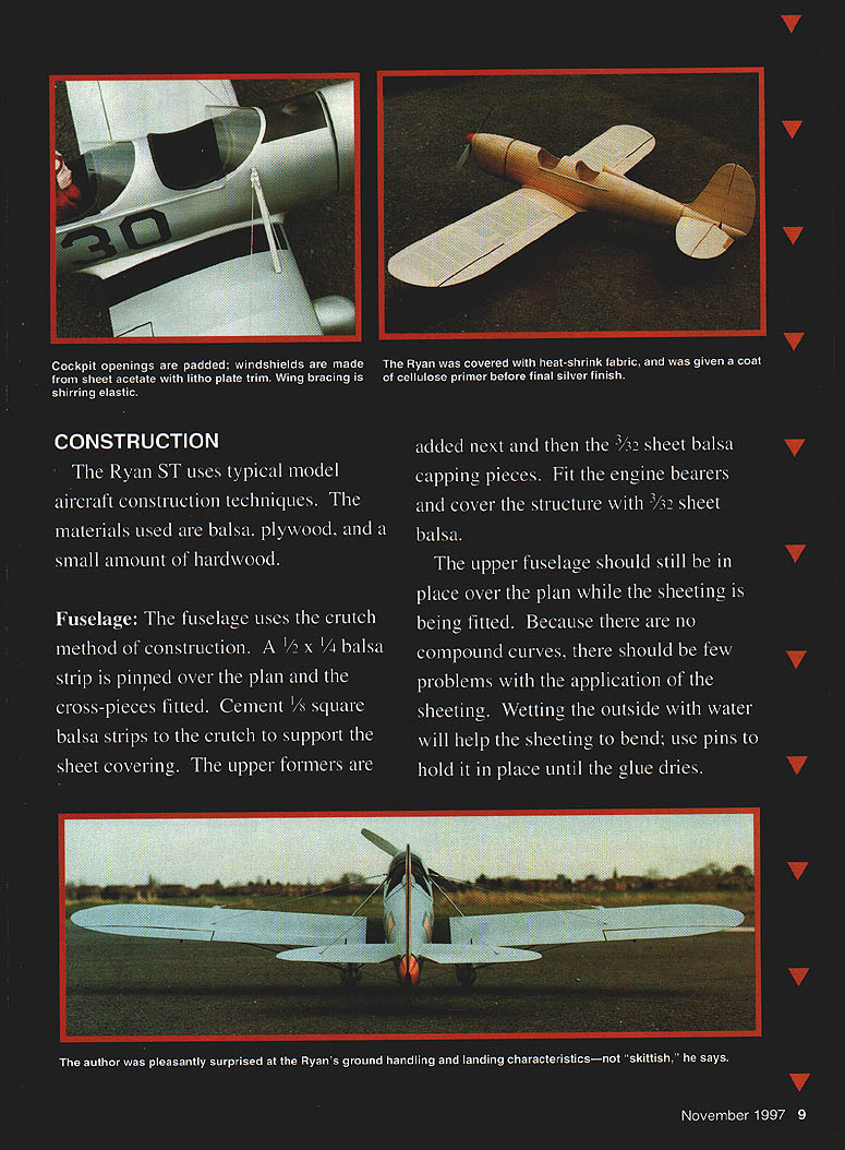
The model was given a coat of cellulose primer before the silver final finish. The markings were masked off and sprayed orange. The black outlines, letters, and numbers were cut from trim film, but the rudder outline was hand-painted. The whole model was then given a coat of fuel proofer; the author mixed equal parts of gloss and matte to give what was considered a more realistic finish.
The rigging for the wings was made from shirring elastic. Flat wire rigging was considered but unnecessary structurally and heavier. The bracing for the tailplane was made from thin round piano wire soft-soldered into brass tubes with flattened ends.
Padding was fitted around the cockpit openings and two dashboards were added. The windscreens are from acetate sheet with a litho plate trim.
Flying
Balance the model where shown on the drawing. There should be no problem getting this right, but the radio gear might need to be located farther aft than normal because of the long nose. The model was fitted with an O.S. 40 Surpass four-stroke engine using an 11 x 7 propeller.
The first flight was from a grass flying field with no problems. The model was taxied out and turned into wind. A quick check confirmed all controls functioning correctly and the engine was run up at full power. The throttle was opened and the model flew away. It proved easy to fly and only a slight amount of down trim was needed (the model had a small amount of up trim set before the first flight as a safety precaution).
Some Ryans have been considered skittish on the ground; the author was pleasantly surprised with the ground handling and the effortless way that three-point landings can be achieved. The model is mildly aerobatic, but with the O.S. 40 Surpass speed has to be built up in a dive before maneuvers. A newer, larger-capacity O.S. 52 Surpass engine might give livelier performance.
The Ryan ST is easy to build, looks good, and is fun to fly—are you tempted?
Phillip S. Kent 32 Moorbottom Cleckheaton W. Yorkshire BD19 6AD England
Transcribed from original scans by AI. Minor OCR errors may remain.

