
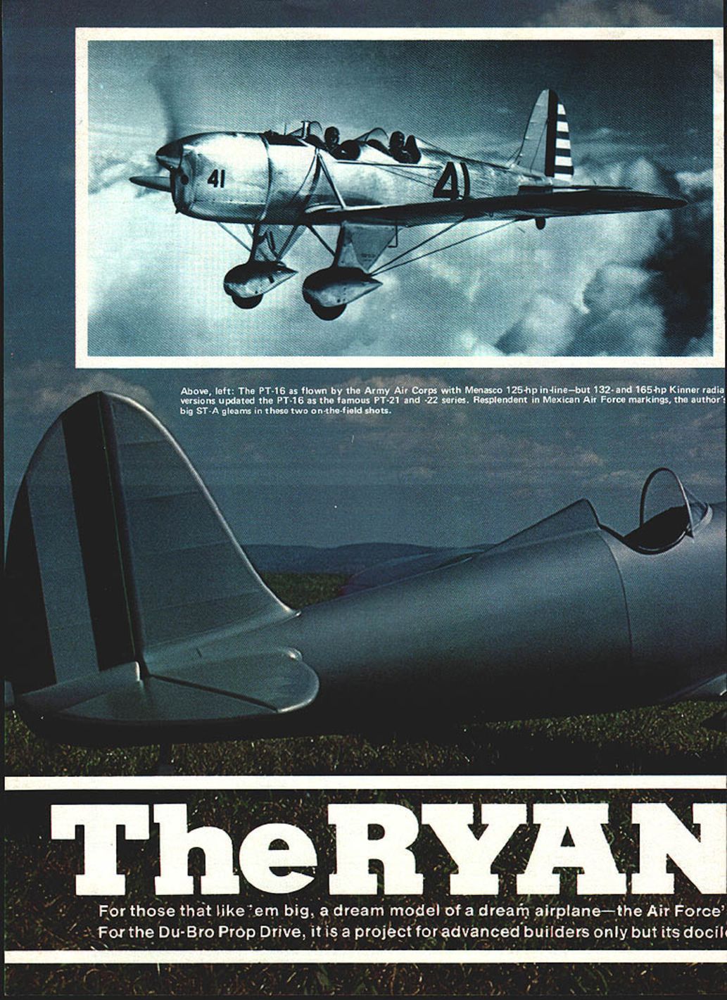
The Ryan ST-A
For those who like them big, the Ryan ST-A is a dream model of a dream airplane. Designed originally as the Ryan ST (Sport Trainer), the ST-A "Super Sport" was an aerobatic and training aircraft notable for its slender, wire-braced monoplane layout and polished-metal appearance. This article covers the full-size history and a detailed quarter-scale scratch-built model using the Du-Bro Prop Drive Unit.
History
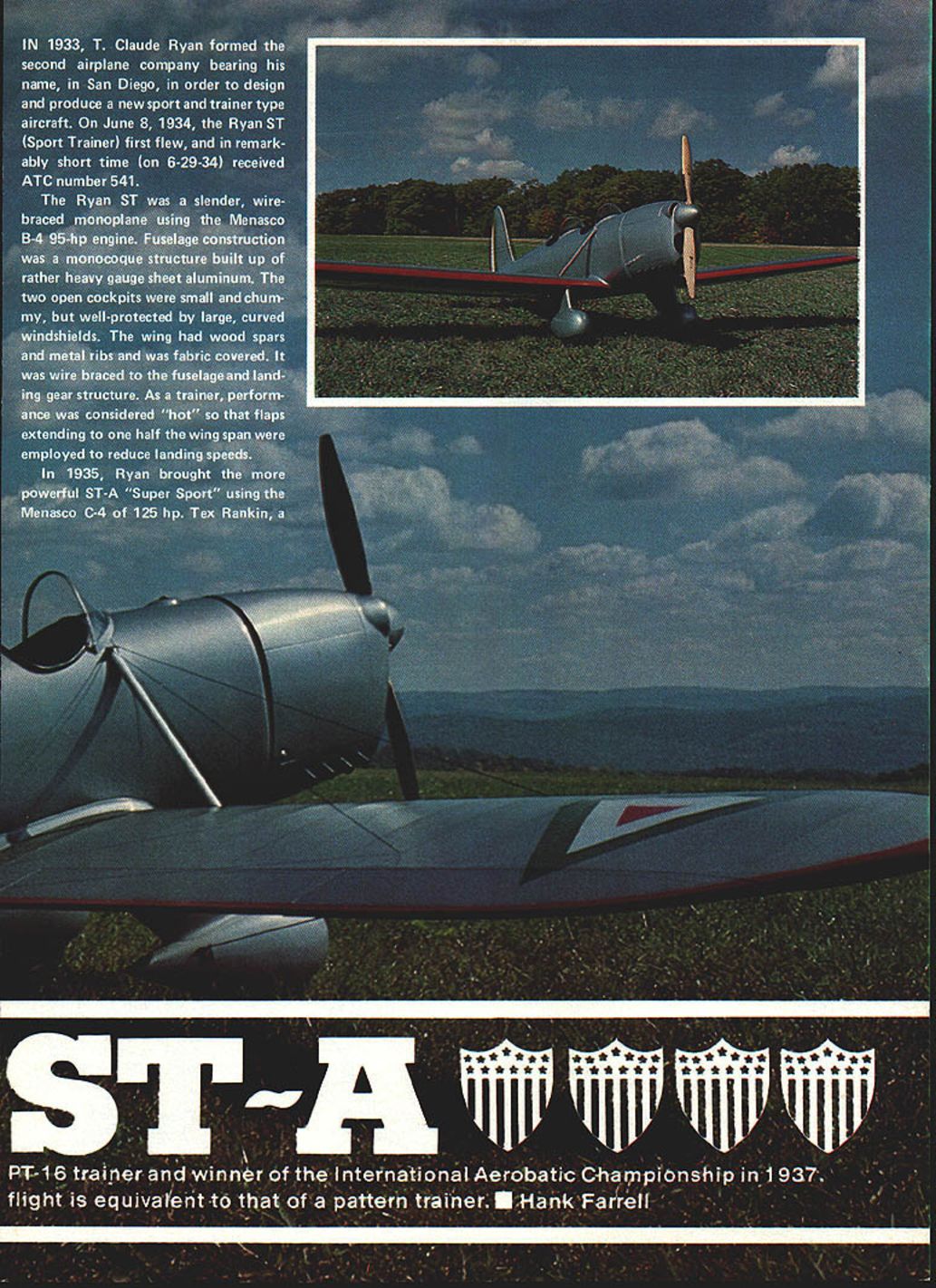
- In 1933 T. Claude Ryan formed his second airplane company in San Diego to design a new sport and trainer aircraft.
- The Ryan ST first flew on June 8, 1934, and received ATC number 541 on June 29, 1934.
- The original ST used the Menasco B-4 95-hp engine. The ST-A ("Super Sport") introduced in 1935 used the Menasco C-4 of 125 hp.
- Tex Rankin set a light-plane altitude record of 29,800 ft and in May 1937 won the International Aerobatic Championship in a stock Ryan ST-A.
- ST-As were sold as military trainers to several foreign countries. In the U.S. the type evolved into the PT-16; slightly improved models became the PT-20. Menasco engines were found unsuitable for military training, so Kinner radial engines (132 hp and 165 hp) were adopted, producing the PT-21/PT-22 families used to train thousands of pilots in World War II.
Model Overview
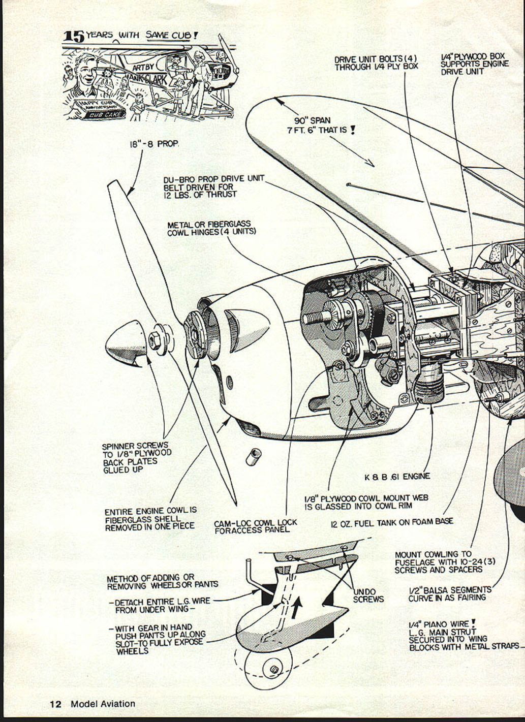
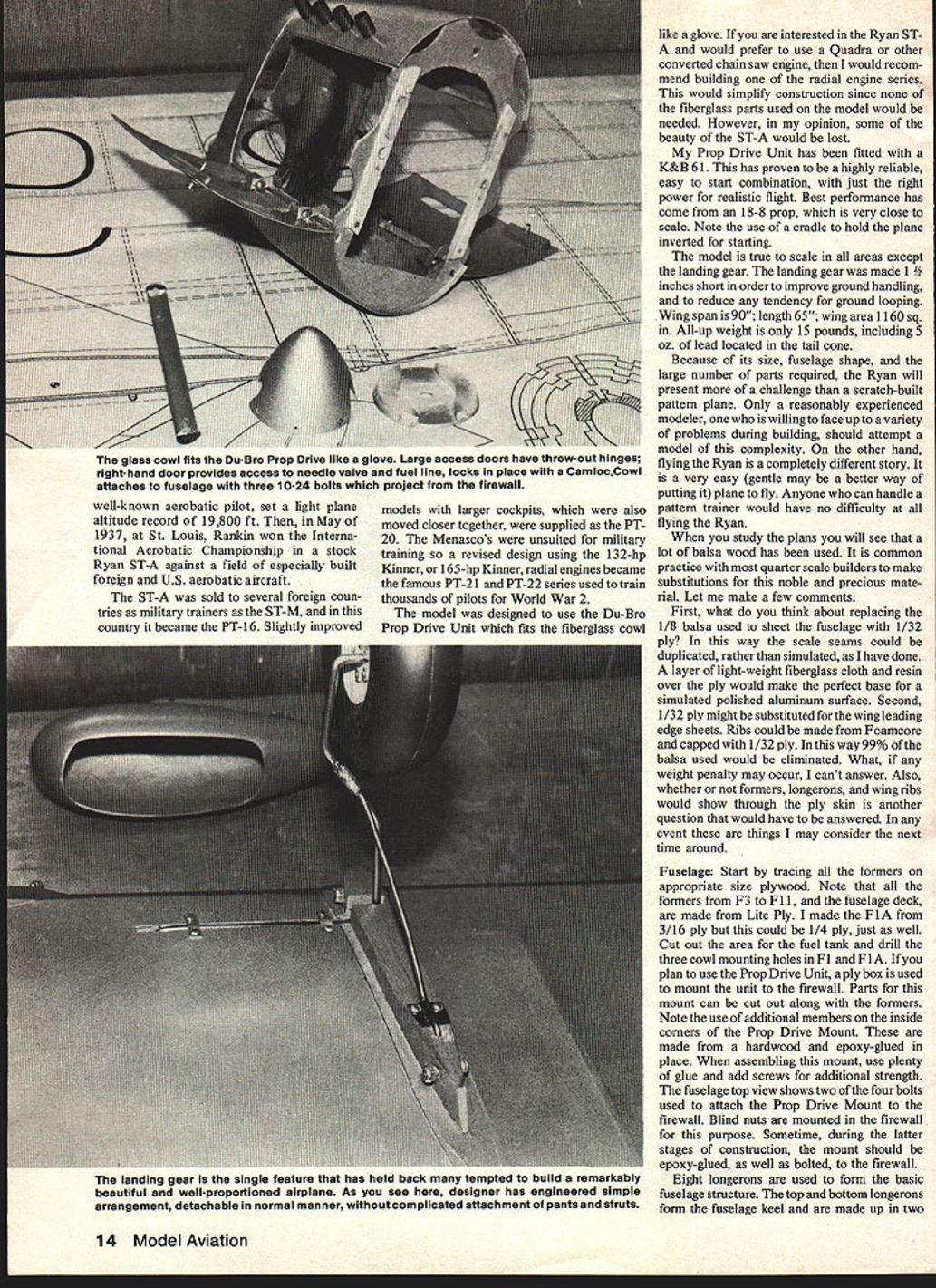
- The model is designed to use the Du-Bro Prop Drive Unit — it fits the fiberglass cowl closely.
- The Du-Bro Prop Drive Unit has been fitted with the K&B .61 and is reliable and easy to start. Best performance has come with an 18 x 8 prop (close to scale).
- Note: use a cradle to hold the model inverted when starting the engine.
- The model is true to scale in most areas except the landing gear, which was made 1" shorter to improve ground handling and reduce ground-loop tendency.
Specifications:
- Wingspan: 90 in (7 ft 6 in)
- Length: 65 in
- Wing area: 1,160 sq in
- All-up weight: 15 lb (including 5 oz lead in the tail cone)
Because of its size, fuselage shape and the number of parts required, the Ryan model is a real challenge for the scratch-built pattern-plane builder. Only a reasonably experienced modeler willing to face a variety of problems during construction should attempt it. Flying the Ryan, however, is easy and gentle — anyone who can fly a pattern trainer should have no difficulty.
Materials and Construction Notes
- Quarter-scale builders commonly substitute materials to reduce use of precious balsa. Two suggested substitutions:
- Replace 1/8" balsa sheet fuselage planking with 1/32" ply and apply a layer of lightweight fiberglass cloth and resin over the ply to provide a good base for a simulated polished-aluminum finish. Scale seams can be duplicated rather than simulated.
- Substitute 1/32" ply for wing leading-edge sheets. Consider foam-core ribs capped with 1/32" ply to eliminate most balsa. Weight penalty and visible rib/former outlines under the ply are unknowns to be evaluated by the builder.
Fuselage
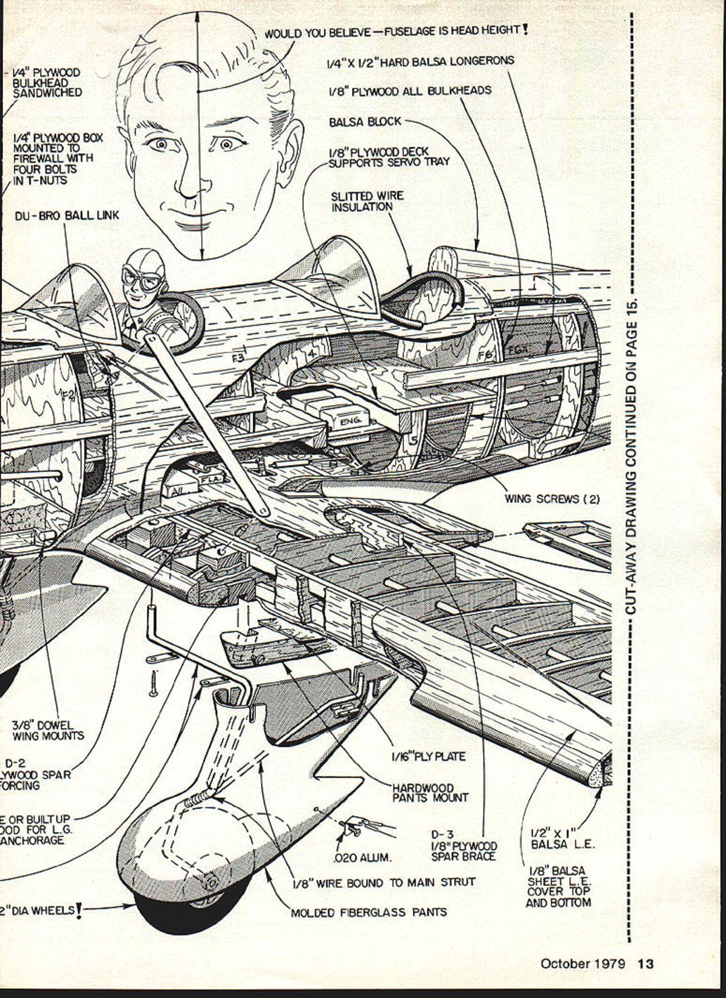
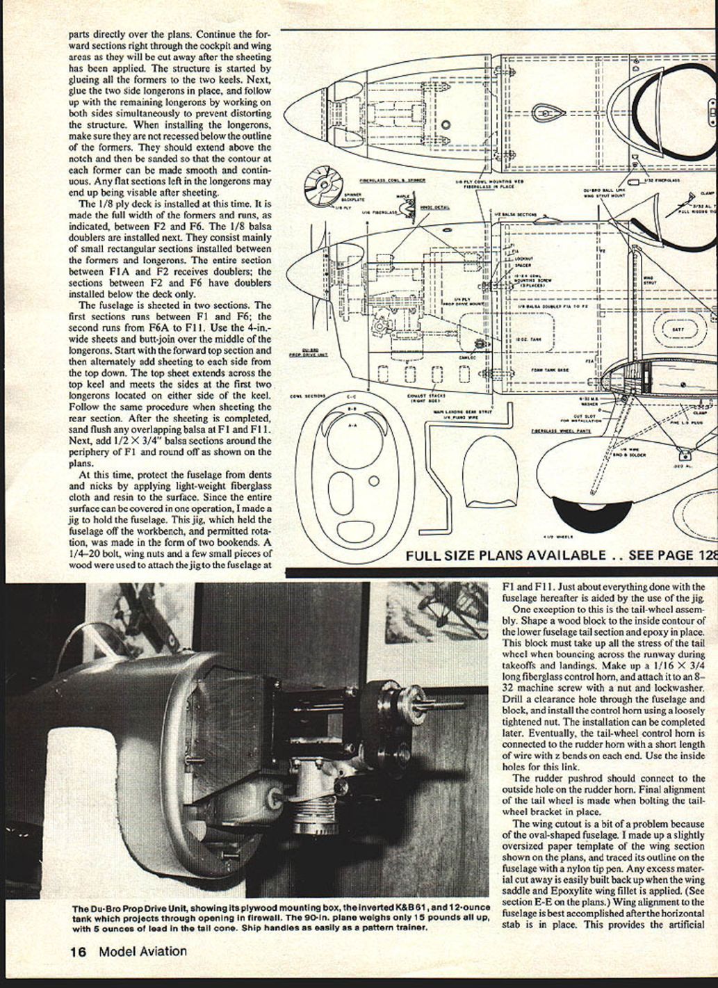
- Start by tracing formers on appropriate plywood. Note formers F3, F1; the fuselage deck is made from Lite Ply.
- F1 is 3/16" ply (1/4" may be used). Cut out the fuel-tank area and drill three cowl-mounting holes.
- F1 and F1A on the plan are used for the Prop Drive Unit ply box and mounting to the firewall. Parts for this mount can be cut out with the formers.
- Use hardwood corner members in the Prop Drive Mount; epoxy-glue and reinforce with screws for strength. Blind nuts are mounted in the firewall; epoxy-glue and bolt the mount to the firewall during later assembly.
- Eight longerons form the basic fuselage structure. The top and bottom longerons form the keel and are made in two lengths.
- Glue all formers to the two keels, then glue the two side longerons, followed by remaining longerons working symmetrically to avoid distortion. Longerons should extend above former notches and then be sanded to smooth contours.
- Install the 1/8" ply deck full-width between F2 and F6. Install 1/8" balsa doublers (small rectangular sections between formers and longerons) — the whole section between F1A and F2 receives doublers; between F2 and F6 they are below the deck only.
- Sheet the fuselage in two sections: F1–F6 and F6A–F11. Use 4" wide sheets and butt-join over the middle of the longerons. Start with the forward top and alternately sheet each side from top down. After sheeting, sand overlapping balsa flush at F1 and F11 and add 1/2" x 3/4" balsa sections around the periphery of F1, rounding as shown.
- Protect the fuselage surface by applying lightweight fiberglass cloth and resin. A jig that holds and rotates the fuselage makes this task much easier — mount at F1 and F11 with 1/4-20 bolts and wing nuts.
- Tail-wheel assembly: shape a wood block to the inner contour of the lower tail section and epoxy in place to absorb tail-wheel stresses. Make a 1/16" x 3/4" long fiberglass control horn and attach to an 8-32 machine screw with nut and lockwasher. Drill clearance holes and loosely install the control horn; final installation is completed later. Tail-wheel control via wire link with two bends on each end; use inside holes for this link. Rudder pushrod connects to the outside hole on the rudder horn. Final alignment is made when bolting the tail-wheel bracket.
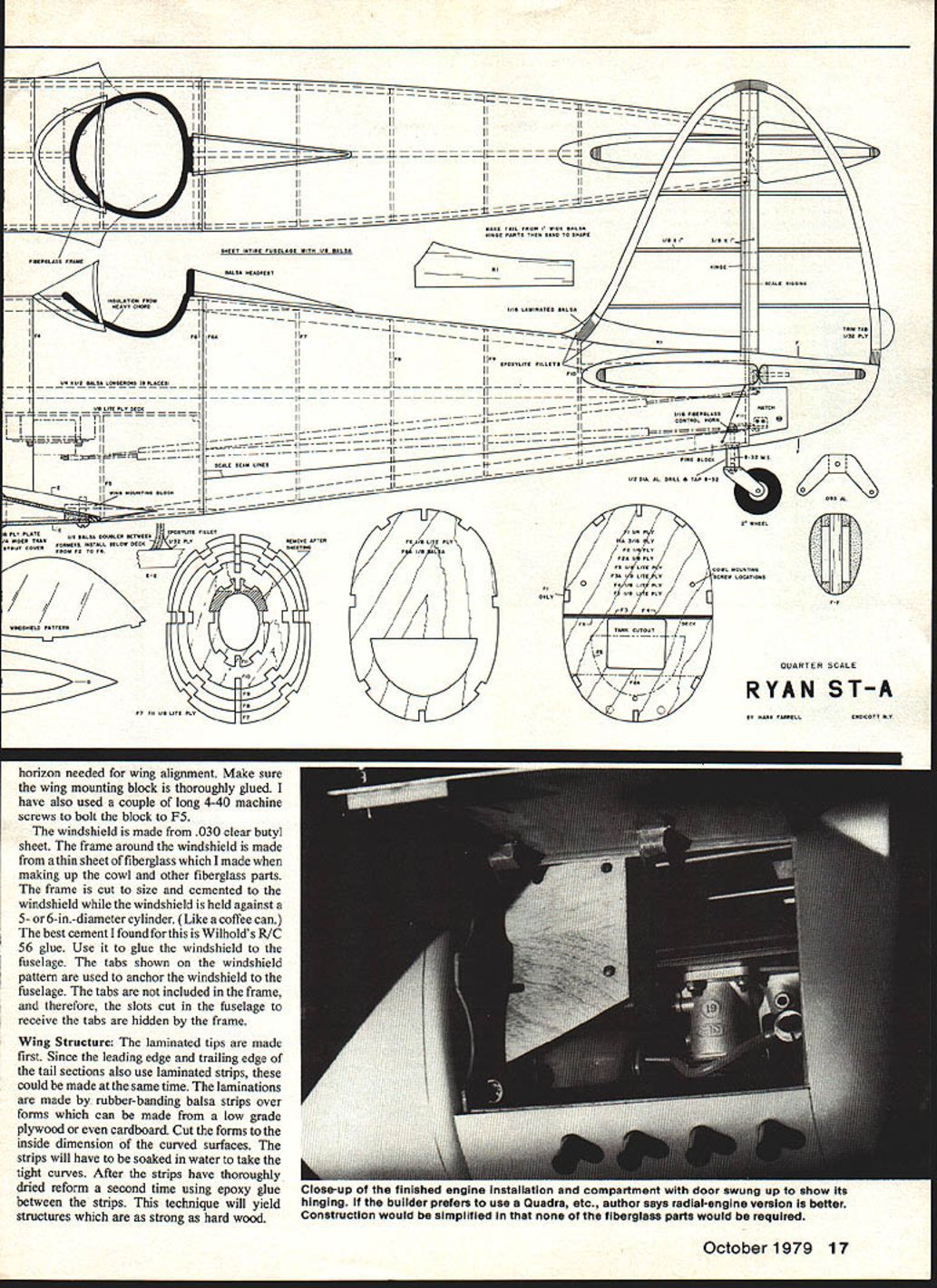
Wing cutout and alignment:
- Make a slightly oversized paper template of the wing section, trace onto the fuselage, and cut. Excess material can be rebuilt when fitting the wing saddle and Epoxylite wing fillet (see section E-E on the plans).
- Align the wing after the horizontal stab is installed to provide an artificial horizon. Make sure the wing mounting block is thoroughly glued; consider using long 4-40 machine screws to bolt the block to F5.
Windshield:
- Made from .030" clear butyl sheet. The frame is a thin fiberglass sheet made when molding the cowl. Cement the frame to the windshield while forming over a 5–6" diameter cylinder (a coffee can works). Best cement found: Wilhold's R/C 56 glue. Tabs on the windshield pattern anchor it to the fuselage; frame hides the slots made for the tabs.
Parts and material callouts (selected):
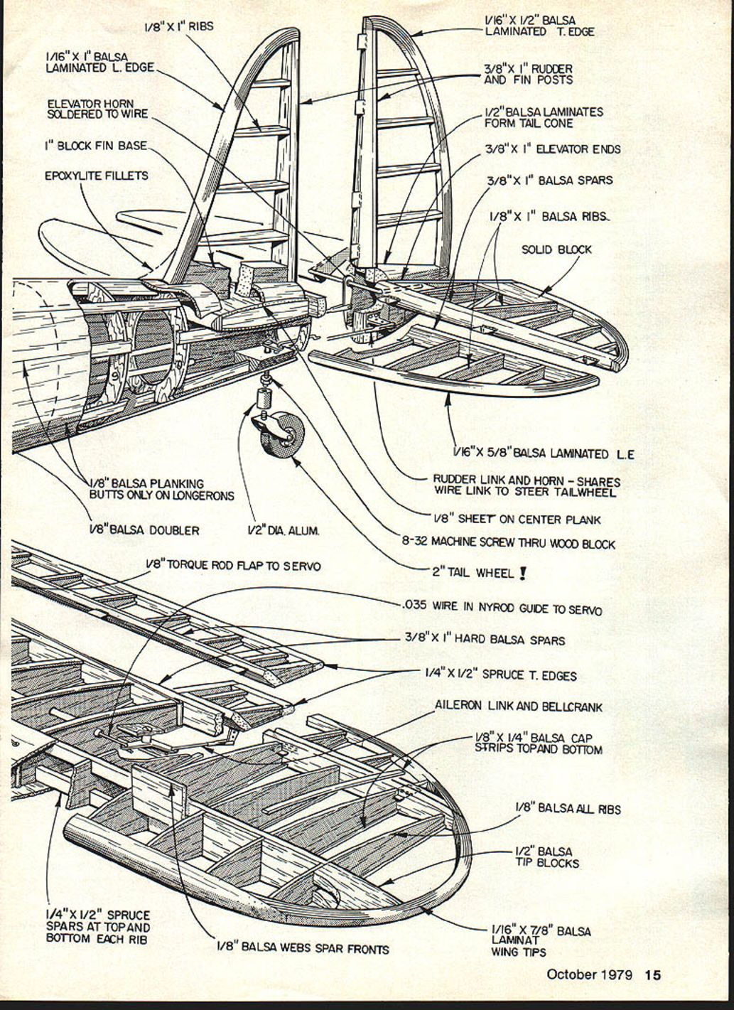
- 1/8" x 1" balsa ribs
- 1/16" x 1" balsa laminated leading edge
- Elevator horn soldered to wire
- 1" block fin base
- Epoxylite fillets
- 1/16" x 1/2" balsa laminated trailing edge
- 3/8" x 1" rudder and fin posts
- 1/2" balsa laminates form tail cone
- 3/8" x 1" elevator ends
- 3/8" x 1" balsa spars
- Solid blocks as required
- 1/16" x 5/8" balsa laminated wing tips
- Rudder link and horn shares wire link to steer tailwheel
- 1/8" sheet on center plank
- 8-32 machine screw thru wood block
- 2" tail wheel (1/2" dia. aluminum)
- 1/8" balsa doublers
- 1/8" balsa planking butts only on longerons
- 1/8" torque rod flap to servo
- .035" wire in Nyrod guide to servo
- 3/8" x 1" hard balsa spars
- 1/4" x 1/2" spruce top edges
- Aileron link and bellcrank
- 1/8" x 1/4" balsa cap strips top and bottom
- 1/8" balsa all ribs
- 1/2" balsa tip blocks
- 1/16" x 7/8" balsa laminate wing tips
- 1/8" balsa web spar fronts
- 1/4" x 1/2" spruce spars at top and bottom each rib
(Parts are typically cut directly over the plans and forward sections continued through cockpit and wing areas to be cut away after sheeting.)
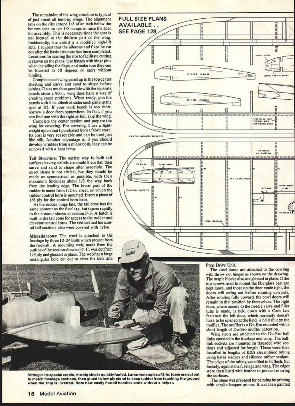
Wing Structure
- Make laminated tips first. Use rubber bands to laminate balsa strips over forms cut from low-grade plywood or cardboard. Soak strips in water to take tight curves, dry, then re-form with epoxy between strips for strength.
- Alignment tabs on ribs extend 1/8" below the bottom spar; use 1/8" scrap to raise spar for assembly because the spar is not at the wing's thickest part.
- Airfoil: modified high-lift Ritz. Cut ailerons and flaps after basic structure is completed. Plans show rib scoring locations for ease of cutting. Use hinges with hinge pins for flaps; ensure flaps can lower to 50° or more without binding.
- Complete each wing panel up to top center sheeting; carve and sand to shape before joining. Join panels with 3" dihedral under each panel at the spar at R3.
- If bench space is short, work on panels separately and assemble where space allows. Complete the center section and prepare the wing for covering.
- Covering: lightweight nylon from a fabric store works like silk, is inexpensive, and minor wrinkles can be removed with a heat lamp.
Tail Structure
- Build tail surfaces flat, then carve and sand airfoil shapes after assembly. Aim for symmetry; maximum thickness about 1/3 chord from the leading edge.
- Lower part of the rudder is made from 1/2" sheet and includes a 1/8" ply insert for the control-horn base.
- At the rudder hinge line, the tail cone follows the fuselage contour, tapering rapidly to the contour shown at section F-F. Build a hatch in the tail cone for access to rudder and elevator control horns.
- Cover vertical and horizontal tail sections with nylon like the wing.
Prop Drive Unit
- The cowl doors are attached to the cowling with throw-out hinges. Maple blocks are glassed in place to support the doors.
- Mounting technique: keep top screws on the fiberglass part loose and screws on the door tight so doors swing out before rotating upward; they then remain open. The right door provides access to the needle valve and filler tube and is held with a Cam-Loc fastener; the left door is normally held shut by the muffler.
- The muffler is Du-Bro-mounted with a short Du-Bro muffler extension.
- Wing struts attach to Du-Bro ball links epoxied in fuselage and wing. Ball link sockets are mounted on threaded wire and installed in K&S streamlined tubing, cushioned with balsa wedges and silicone sealant. File tube edges to fit flush and line with leather to avoid marring.
- The Prop Drive Unit fits the fiberglass cowl well and, paired with a K&B .61 and an 18x8 prop, produces realistic flight power and reliable starting.
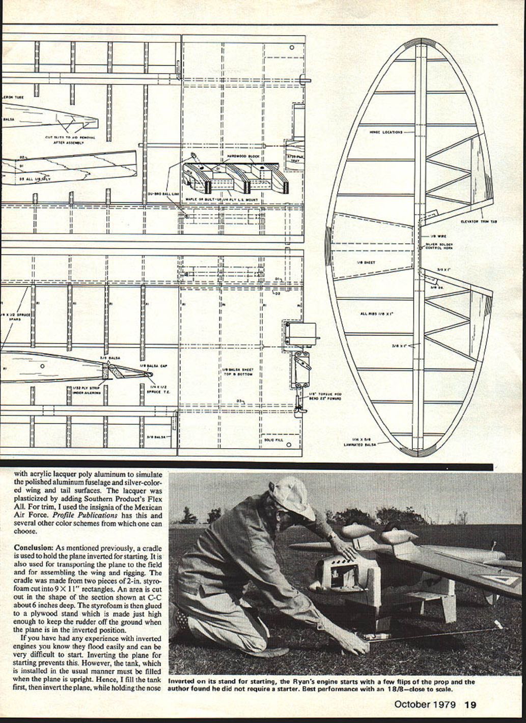
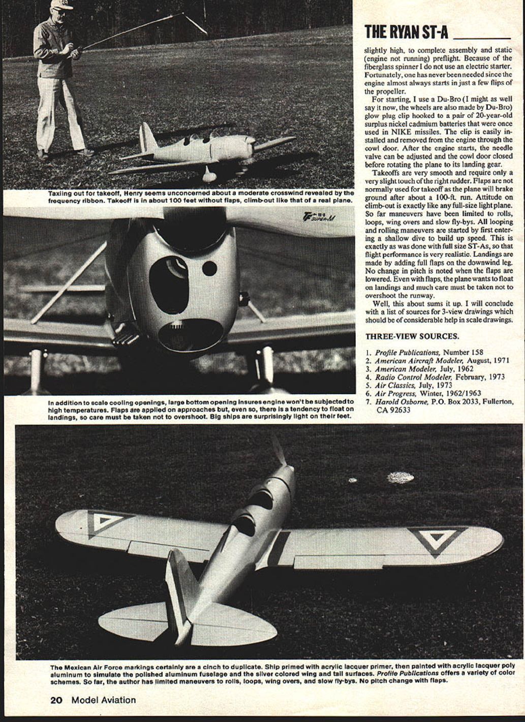
Finishing and Painting
- Prepare for painting by priming with acrylic lacquer primer. Paint with acrylic lacquer poly-aluminum to simulate polished fuselage and silver-colored wing and tail surfaces. Plasticize lacquer by adding a flexibleizer (e.g., Southern Products' Flex-All).
- Trim and insignia: one author used Mexican Air Force insignia. Profile Publications and other sources offer color schemes.
Flying and Handling
- Use a cradle to hold the plane inverted for starting; the same cradle is useful for transport and wing assembly/rigging.
- The cradle described: two 2" styrofoam pieces cut to 9 x 11", with a 6" deep cutout shaped for section C-C, glued to a plywood stand just high enough to keep the rudder off the ground when inverted.
- Fill the fuel tank while the plane is upright, then invert the plane for starting while holding the nose wheel off the ground. Inverted engines can flood and be difficult to start; inverting the model prevents this.
- The author avoids electric starters because of the fiberglass spinner; engines usually start in a few flips of the prop.
- For starting, the author used a Du-Bro glow plug clip connected to a pair of surplus nickel-cadmium batteries once used in NIKE missiles. The clip is accessible through the cowl door.
- After start, adjust the needle valve and close the cowl door before rotating the plane down to its landing gear.
- Takeoffs: smooth, requiring only slight right rudder. Flaps are not normally used for takeoff; the plane will lift after about a 100-ft roll. Climb attitude is like a full-size light plane.
- Maneuvers flown: rolls, loops, wingovers and slow fly-bys. Rolls and loops are typically begun from a shallow dive to build speed, as with full-size ST-As, yielding realistic performance.
- Landings: add full flaps on the downwind leg. The plane tends to float even with flaps; do not overshoot the runway.
Conclusion
- The Ryan ST-A model is a rewarding but demanding build. It requires experience and patience to scratch-build the many parts and complex fuselage shape, but it results in an attractive, docile flyer with realistic handling.
- Use the cradle for starting, transport and rigging. Fill the tank upright, invert for starting, and expect reliable engine starts with the proper setup.
Three-View Sources
- Profile Publications, Number 158
- American Aircraft Modeler, August 1971
- American Modeler, July 1962
- Radio Control Modeler, February 1973
- Air Classics, July 1973
- Air Progress, Winter 1962/1963
- Harold Osborne, P.O. Box 2033, Fullerton, CA 92633
Transcribed from original scans by AI. Minor OCR errors may remain.

