

S2 B2 (Solid State Battery Backer)
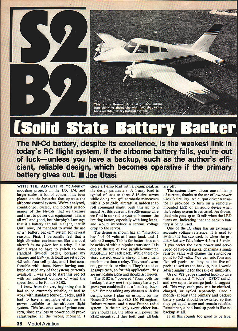
The Ni-Cd battery, despite its excellence, is the weakest link in today's RC flight system. If the airborne battery fails, you're out of luck—unless you have a backup. The S2B2 is an efficient, reliable solid-state backup that becomes operative if the primary battery gives out. — Joe Utasi
Design Goals
- Extremely reliable in a high-vibration environment.
- Works with standard four-cell (4.8 V nominal) Ni-Cd packs.
- Negligible effect on the power available to the airborne flight system.
- Designed to handle a continuous 1 A load with a 2 A peak.
A 1 A load is typical of two or three S-16-size servos during busy aerobatics on a 15–20 lb aircraft; a sudden snap-roll command might push this to 2 A. At these currents, wiring (especially #26 gauge with long leads) becomes a limiting factor—voltage drop to the servos must be minimized.
The S2B2 design achieves an insertion loss of about 0.05 V at a 1 A load and about 0.1 V at 2 A. This low loss is accomplished by using two parallel MOSFETs per pack as the series pass elements. MOSFETs are preferred over relays (no wear, no sticking from vibration) and over bipolar transistors (lower loss and easier drive).
Overall Concept
- The S2B2 is powered by both the primary and the backup battery packs. Either battery can supply power to the S2B2 circuitry in the unlikely event the other fails.
- The system draws about 1 mA in standby, thanks to low-power CMOS circuitry.
- An output driver transistor turns on a remotely mounted LED or audio device when the backup system is active; this indicator can draw up to about 10 mA.
- A voltage reference in the control IC switches to the backup pack when the primary falls below about 4.2–4.3 V. Changing one resistor value will shift the switchover point (for example, to ~5.5 V for five-cell packs).
Electrical Design and Operation
Gate Drive
- To properly turn on MOSFETs in a series-pass configuration, the gate voltage must be 4–6 V higher than the source. With a nominal 5 V pack, a gate drive of roughly 9–11 V is required.
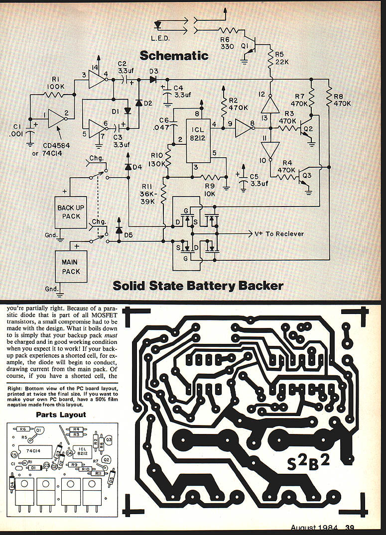
- The S2B2 uses a cascaded voltage tripler driven by a 74C14 (hex Schmitt-trigger inverter) oscillator to produce about 14 V gate drive. R1 and C1 with one inverter form a ~10 kHz oscillator; the next two gates form a 180° push-pull drive for the diode-capacitor ladder (D1–D3, C2–C4) that steps the voltage up ~3× (minus diode drops).
- Converter efficiency is around 75%, but total current drain is very small (~100 µA for the converter itself).
Logic and Switching
- One IC contains an accurate voltage reference that senses the main pack voltage and commands the switch to the backup when the threshold (~4.2–4.3 V) is crossed.
- C6 forms a power-on reset ensuring the main battery is preferred at power-up. Once the circuit latches to the backup, it will remain there until the power switch is reset or the main pack rises above the reset threshold (about 5.4 V). This makes behavior similar to a latching relay: momentary glitches won't re-engage the main pack until landing and reset.
- Q1 drives the remote indicator when the backup is in use. Q2 and Q3 level-shift the 14 V gate drive on and off to the MOSFET gates.
MOSFET Orientation and Parasitic Diode
- Most power MOSFETs contain a parasitic body diode that could conduct between packs if the devices were connected in the expected source/drain orientation. The S2B2 takes advantage of reasonably symmetrical MOSFET characteristics and swaps source/drain connections to minimize undesirable conduction between packs.
- This approach mitigates the parasitic diode issue in all realistic operating conditions, provided the backup pack is healthy.
Components and Substitutions
MOSFETs
- Aim for Rds(on) ≤ 0.1 ohm per device. Two MOSFETs are paralleled for each pack, giving an effective in-line resistance of ≤ 0.05 ohm.
- Suggested MOSFETs:
- Supertex VN2306NS
- Siemens BUZ-10 or BUZ-71
- International Rectifier IRF540
- RCA RFP25N06
- Motorola MTP25N05
- Do not substitute standard bipolar transistors (require more drive, higher loss, incompatible with board layout).
Diodes and Capacitors
- Use 1N5817 Schottky rectifiers for the voltage tripler and isolation diodes because of their low forward drop (~0.1 V) and low reverse leakage. Do not use silicon or germanium diodes.
- C2–C4 should be dipped tantalum capacitors (3.3 µF, 15 V or higher). Do not substitute electrolytics (too leaky for the up-converter).
- If 3.3 µF tantalums are unavailable, values up to 10 µF are acceptable (≥15 V rating).
- C5 stabilizes the diode-isolated pack voltages against switching transients.
- C6 is a small capacitor mounted on the bottom of the PC board between pins 2 and 8 of the ICL8212 and provides power-on reset behavior.
- C1 and C5–C6 are non-polar monolithic capacitors as listed.
ICs and Transistors
- IC1: CD4584 or 74C14 (hex Schmitt trigger / inverters)
- IC2: ICL8212CPA (voltage reference/compare)
- Q1, Q2, Q3: 2N3904 small-signal transistors
Construction and Assembly
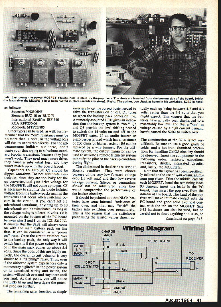
- Use #22-gauge stranded hookup wire for pack connections and a standard DPDT (Noble) switch plus two separate charge jacks so each pack can be checked, charged, and cycled separately.
- Recommended assembly order: resistors, capacitors, transistors, diodes, integrated circuits, and lastly the MOSFETs.
- Use a good grade of solder and a hot iron. Observe standard CMOS handling precautions (ESD).
- The PCB layout is tailored for 1/2-in. diameter aluminum pop rivets to make good thermal and electrical contact with the MOSFET tabs:
- Trim the middle lead off each MOSFET, bend remaining leads 90°, insert leads into the PCB, and insert the pop rivet from the bottom. The rivet head will contact the MOSFET tab and PCB.
- 6-32 hardware can be used if careful to avoid shorts.
Parts Layout / Build Sequence (summary)
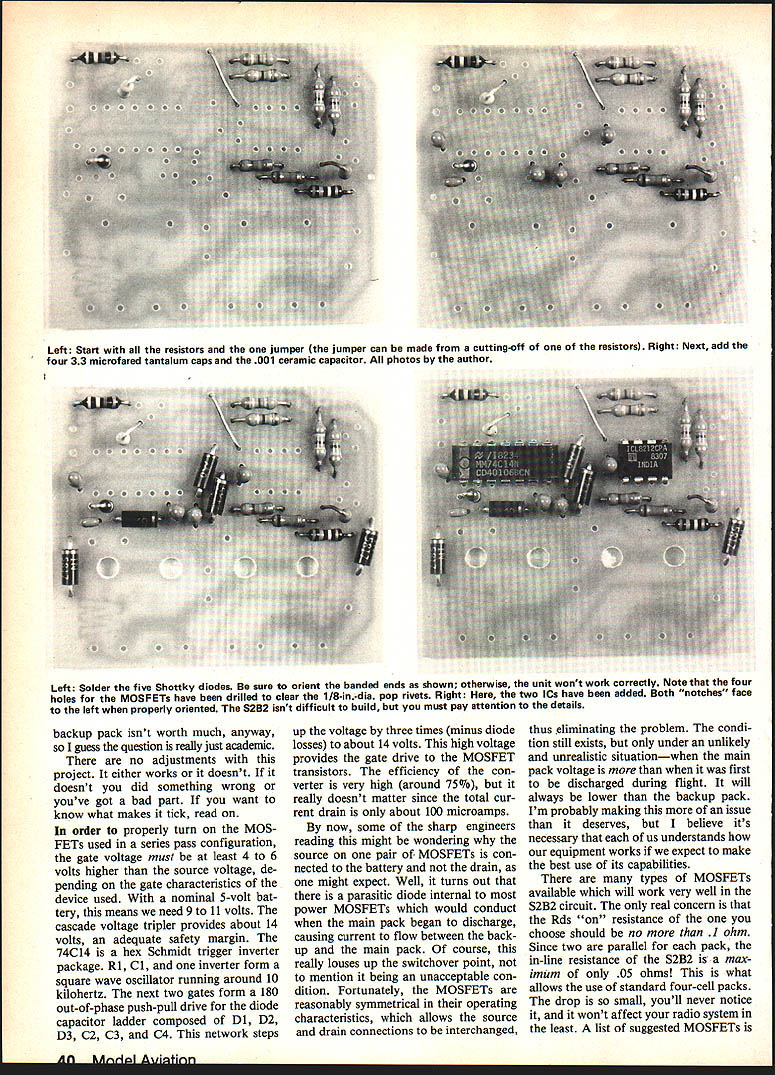
- Install resistors first (cut resistor leads to form jumpers where needed).
- Add the 3.3 µF tantalum capacitors and the small ceramic (C1).
- Solder the Schottky diodes with correct polarity (banded ends as indicated).
- Drill MOSFET holes clear for pop rivets if necessary.
- Install the ICs (notches oriented correctly).
- Install MOSFETs and secure tabs with rivets or hardware.
Usage and Maintenance
- Monthly (at least) swap primary and backup packs so both receive equal usage and remain reliable. A bad backup pack is effectively no backup at all.
- Use standard four-cell packs unless you intentionally change the switchover resistor to support five-cell packs. Mixing four- and five-cell packs is possible only if the five-cell pack is the backup, but simplicity recommends using matching pack types.
- The backup pack must be charged and in good condition. If a backup pack contains a shorted cell, the parasitic diode path can draw current from the main pack, causing undesired behavior.
Warnings and Notes
- Ni-Cd internal resistance can cause transient voltage dips under high current draw; the chosen switchover point (4.2–4.3 V) accounts for this so the backer does not switch on brief drops.
- There are no user adjustments. If the unit does not work, verify assembly and check parts.
- The system will latch to the backup on a power glitch and remain on until reset or until the main pack is restored above the threshold.
Availability
- PC board only: $7.50 (Jomar Products, 2028 Knightsbridge Dr., Cincinnati, OH 45244).
- Assembled unit (less switch and wiring): $44.00 (order from Jomar Products).
- Fully assembled units, complete with wiring, switch, and connectors to match your radio system, are available from EMS, 6175 Palo Alto Dr., Anaheim, CA 92807—write for pricing.
Parts List
- R1 — 100K
- R2, R3, R4, R7, R8 — 470K
- R5 — 22K
- R6 — 330 ohm
- R9 — 10K
- R10 — 130K
- R11 — 36K–39K (use 47K for five-cell pack switchover)
- D1 through D5 — 1N5817 Schottky diodes
- Q1, Q2, Q3 — 2N3904
- IC1 — CD4584 or 74C14
- IC2 — ICL8212CPA
- C1 — 0.001 µF monolithic (1 nF)
- C2, C3, C4 — 3.3 µF dipped tantalum, 15 V or higher
- C5, C6 — 0.047 µF monolithic (47 nF)
Miscellaneous:
- PC board, solder, wire (#22 gauge recommended), DPDT switch, 1/2-in. aluminum pop rivets (or size 6-32 hardware), connectors to suit your radio system, LED for indicator.
Transcribed from original scans by AI. Minor OCR errors may remain.

