
S2F Tracker
Updated as a firebomber, this Control Line Scale twin-.049 model of a lesser-known Grumman design is guaranteed to turn heads at the flying field. ■ Allen Wulf
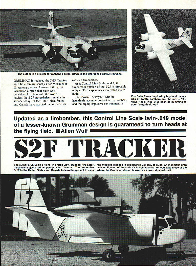
Grumman introduced the S-2F Tracker with little fanfare shortly after World War II. Among the least known of the great Grumman aircraft that have seen considerable action with the world's navies, the S-2F nevertheless remains in service today. In fact, the United States and Canada have adapted the airplane for use as a firebomber.
As a Control Line Scale model, this firebomber version of the S-2F is probably unique. Two experiences motivated me to build it. The first — seeing vintage firebombers and other large aircraft in action — took me back to the summer I was 10. On many a hot afternoon I'd watch excitedly as B-17s, B-26s, and PBY-4Ys were fueled up, filled with thick red borate, and taxied to the end of the runway. Seeing, hearing, and feeling those big machines as they rumbled and staggered into the air was a real thrill.
The second was an article in Air & Space magazine about contemporary use of the Grumman S-2F as a firebomber. I suppose the diminishing supply of WW II bombers made this inevitable, yet I had never thought of the S-2F as a potential attack plane. To me it was strictly a submarine hunter, equipped with a supply of sonar buoys but little else; I hadn't imagined it carrying torpedoes as well.
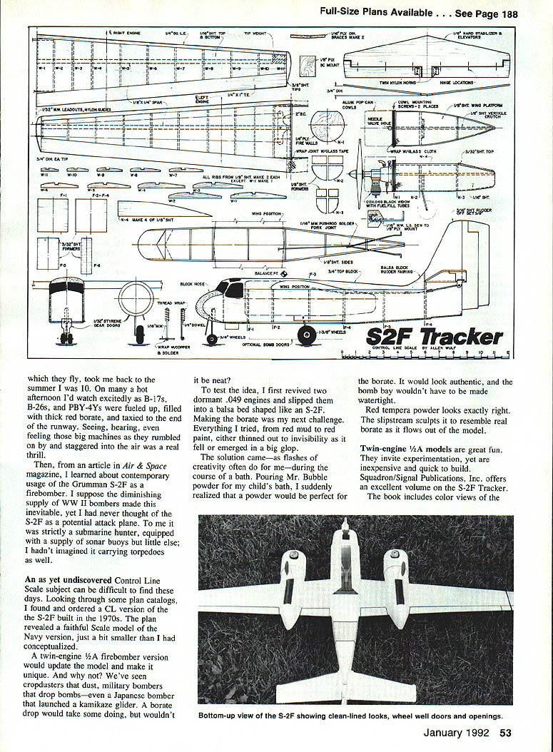
As yet-undiscovered Control Line Scale subjects can be difficult to find these days. Looking through some plan catalogs, I found and ordered a CL version of the S-2F that had been built in the 1970s. The plan revealed a faithful scale model of the Navy version, just a bit smaller than I had conceptualized.
A twin-engine 1/2A firebomber version would update the model and make it unique. And why not? We've seen cropdusters that dust, military bombers that drop torpedoes—even a Japanese bomber that launched a kamikaze glider. A borate drop would take some doing, but wouldn't it be neat?
To test the idea, I first revived two dormant .049 engines and slipped them into a balsa bed shaped like an S-2F. Making the borate was my next challenge. Everything I tried, from red mud to red paint, either thinned out to invisibility as it fell or emerged in a big glop.
The solution came — as flashes of creativity often do for me — during the course of a bath. Pouring Mr. Bubble powder for my child's bath, I suddenly realized that a powder would be perfect for the borate. It would look authentic, and the bomb bay wouldn't have to be made watertight.
Red tempera powder looks exactly right. The slipstream sculpts it to resemble real borate as it flows out of the model.
Twin-engine 1/2A models are great fun. They invite experimentation, yet are inexpensive and quick to build. Squadron/Signal Publications, Inc. offers an excellent volume on the S-2F Tracker. The book includes color views of the S-2F and offers a bit of information about the Turbo-Tracker now being built in Canada. The United States could miniaturize the Turbo-Tracker to a different look entirely, too. If the borate bomber doesn't catch your fancy, you could go torpedo or sonar-buoy drop—or forget about the drop and simply make a fun flier.
Construction
Select test engines before building. Success in a twin-engine model begins with engines that are reliable and matched. You must be able to start the engines quickly and easily, and their power output should be approximately equal. With Control Line models, however, skewing the power output slightly in favor of the inboard engine is an advantage. If the outboard engine quits, a slightly more powerful inboard one will help keep the lines taut.
My borate drop mechanism is too complicated for ready illustration, so I omitted it from the plan. Basically the mechanism involves a set of doors spring-loaded to close with rubber bands. A pair of spring-loaded cams rams the doors open when the cams are tripped by pulling a third lead-out. The system took a lot of monkeying, but it works.
You may well come up with a simpler setup. If so, make a working model of your drop mechanism before building the fuselage. You'll need to adjust the fuselage construction to accommodate your particular system.
Wing
Begin by making the inboard (left) panel. Trim a sheet of 1/16 x 4-in. balsa to fit between the leading and trailing edges (LE and TE). Pin the balsa sheet, LE, and TE over the plan. Glue all ribs except W-1 in place.
Install the bellcrank and its mount. String the lead-outs through the inboard wing. Make the basic pushrod from 1/16 music wire. The pushrod should extend a good eight inches beyond the trailing edge at this point; it will be joined to the rear twin pushrods after the wing has been installed.
When the glue has set, remove the inboard wing from the building board and position it over the plan. Build the right panel directly atop the left.
Pin down the leading and trailing edges, taking care not to glue them to the mating leading and trailing edges of the opposite wing. Glue in ribs W-2 through W-11 and set the wing weight. Cut out the two plywood dihedral joiners, and fit them to the center section; make small balsa wedges to achieve an accurate fit.
Carefully cut the two wing panels apart. Sand in the bevel for the dihedral angle. Pin one panel to the building board, and block up the other 1-1/2 in. Epoxy the panels together. Install the dihedral joiners and W-1.
Add the top wing spar. Lift the wing off the board when the dihedral joint has set, and plank the top surface with 1/16 sheet. Add the wingtip blocks. Drill the lead-out holes and install the bushings in the left tip.
Carve the leading edges and wing tips to shape. Sand the entire wing thoroughly. Coat the center section with epoxy, and reinforce the center joint with lightweight fiberglass cloth.
Tail surfaces and control runs
The high-placed stabilizer with dihedral presents a couple of challenges, so assembling the tail is done a little differently than usual.
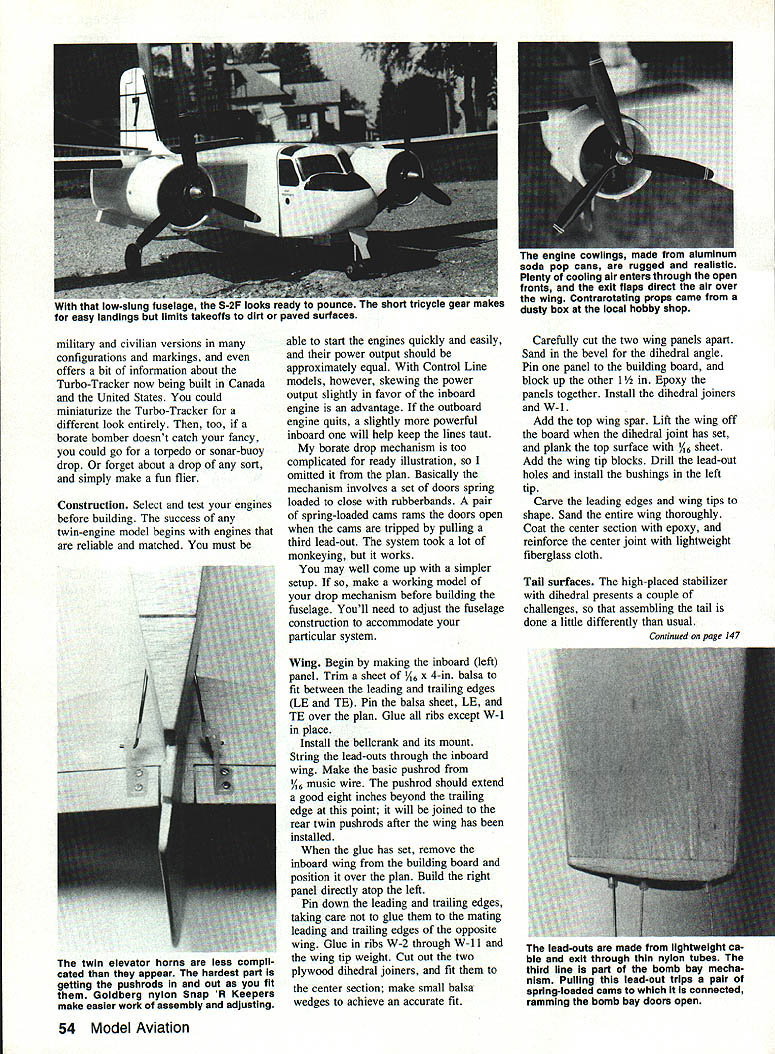
The lead-outs are made from lightweight cable and exit through thin nylon tubes. The thin line is part of the bomb-bay mechanism. Pulling this lead-out trips a pair of spring-loaded cams to which it is connected, ramming the bomb-bay doors open.
Cut out the stabilizer and elevators from stiff 1/8-in. balsa sheet. Trim a gap between these parts to provide 1/16-in. clearance after hinging. Sand all exposed edges and the hinge lines to a round profile. Cut the hinge slots and install the hinges. Use slotted nylon hinges.
Cut the stabilizer along the centerline and bevel the halves to set the dihedral. As you did with the wing, pin one stabilizer half to the board and block up the other half 1/2 in. Epoxy the halves together. Add the fiberglass reinforcement when the glue joint has set.
Cut out the rudder from 3/32-in. soft balsa sheet. Sand a generous airfoil nose on the rudder and round all edges. Fit the rudder into the fuselage and install the hinge line.
Install the control horns on the control surfaces and run the control cables through the nylon tubes. Attach the cables to the spring-loaded cams in the bomb-bay mechanism; pulling the lead-out trips the cams and rams the bomb-bay doors open.
The full-scale S-2F has two hinge lines and a long trim hinge on the rudder. I cut the rudder on the second, or stepped, hinge line, and glued in 3/8 in. of rudder offset. This amount of offset encourages the model to turn right against its flying circle, providing the necessary line tension for the windy conditions in which I fly. It's especially helpful when only one of the engines is running.
Fit the fuselage sheeting and nose blocks. Hollow out the engine nacelles to accept the .049 test engines. Mount the engines on hardwood bearers and align them carefully. Install the landing-gear blocks and make the bottom of the fuselage removable for access to the bomb bay and radio. Make the wing fillets from 1/8-in. balsa and glue them in place.
Balance the model at the point shown on the plans and add ballast as required to achieve the correct center of gravity. Sand the entire airframe smooth and cover with your choice of film or dope and silkspan. Paint the model in the color scheme shown or to represent a firebomber (red and white with appropriate markings).
Install the lead-out guides in the left wingtip and fit the lead-outs. Check the twin engines on a test stand and then run them on the model to make final adjustments. Trim the model for straight-and-level flight and adjust the control throws for the intended flying style.
Flight-test carefully in calm conditions. The borate-drop mechanism uses a simple ejector that releases red tempera powder; do not seal the bomb bay. The slipstream sculpts the powder into a realistic borate flow when released.
Engine pods
The twin pods are identical except for the landing-gear struts and mounts. Beginning with the center crutch, cut out all the parts in pairs. The center crutch should basically match the side view of the nacelle minus the thicknesses of the firewall and sheeting.
Cut out the N-4 pieces, and glue them to both sides of the crutch. Glue in the firewall, N-2, and N-3 on each side. Add the wing platform. Install the landing gear and its plywood anchors, bracing the gear well.
Plank the nacelles. Select pieces of 1/16 A-grain balsa one inch wide by eight inches long, making sure the wood grain runs lengthwise. Soak the pieces in hot water for an hour or two to make them pliable. Wipe off excess water, and fit them roughly over the nacelles. Bind the assembly with an Ace bandage or strips of cloth.
When the pieces are dry, bend and trim them for an accurate fit over the nacelles. Glue the planking in place.
Cap the nacelles with 3/32 sheet when joining them to the wing.
Test fit the nacelles to the wing. This is somewhat complicated by the dihedral angle; bend the landing gear strut to give the nacelles the desired appearance.
Fuselage
Cut out the sides from medium 1/8-in. balsa sheet. Shape the nose block on a bandsaw or jigsaw. Cut out the formers and mark their locations on both sides. Glue the nose block to the sides.
Working from front to rear, add the formers to F-4. Position the assembly over the plan top view. Pull the tail together, making sure the sides meet on the centerline. Attach the tail post with quick-setting glue, and add the remaining formers.
Sheet the fuselage bottom with 3/32 balsa, making certain the wood grain runs crosswise. Drill the hole for the nose gear dowel.
Make the nose gear from 7/16 music wire. Bind and solder the axle securely to the strut. Bend over the top of the strut, bind it to a hardwood dowel as shown, and install it in the hole in the nose block. Check that the axle is straight; otherwise the model will try to taxi into the center of the circle.
Pin the wing assembly in place on top of the fuselage. Trim the openings in the fuselage formers to clear the pushrod from the wing. Mount the two nylon horns to the elevator bellcrank and install the pushrod. Pin the stabilizer in place on the rear of the fuselage. Sight the elevator assembly from the front and rear, trimming as necessary for accurate alignment of wing, stabilizer, and fuselage.
Bend up and install the twin elevator pushrods. Cut exit slots for the pushrods in both sides of the fuselage, and bend the rods a bit to assure that they move freely and link up with the main pushrod. Adjust the slots and wires to achieve a good 1/4 in. up and down elevator travel. When you're satisfied, bind the three pushrods with copper wire and solder them securely. Glue the wing and stabilizer to the fuselage with CyA (cyanoacrylate) glue. When the glue has set, fillet the joints with epoxy.
The top block gives the S-2F its distinctive look. Use lightweight 3/16-in. balsa sheet, if available, or laminate a block from thinner sheets. Rough cut the block to shape, and fit it to the wing.
To help achieve an accurate fit, cut a template from rib W-2 but include an allowance for the leading and trailing edges and the top sheeting. At the rudder/stabilizer juncture, carve the top block to fair into the rudder and the stabilizer shelf. It's worth the effort to achieve the correct appearance.
Carve the top block to final shape. Remove and hollow the block, and glue it back on.
Mount the nacelles to the wings. Accurately measure the distance from the fuselage side to the centerline of each nacelle. Pin the nacelles in place, and check the alignment. Glue on the nacelles with a good-quality slow-drying epoxy.
Mix up some epoxy filler using microballoons or your favorite commercial brand. Both as reinforcement and for appearance's sake, make a small epoxy fillet at all major component joints. When the fillets have set, sand the entire model well. Fill in any dents and pinholes, and sand the structure a final time.
The engine cowlings determined the model's size. The cowlings shown on the plan are about the size of an aluminum soda pop can. Use cans with rounded bottoms; those with an angled base look wrong. You might have to wander into the sparkling water section of the grocer to find the right type.
Before cutting the cans apart, sand them well with 600-grit paper to remove the original paint and roughen the surface so that new paint will adhere. Cut out the can bottom, and punch it with a hole large enough to allow you to finish the job with tin snips. Be careful—the cans are made of very thin metal and have extremely sharp edges.
Cut the cowls to length. Snip short cuts into the rear cowl edge to make the cooling air exit flaps.
Finishing and final assembly
Finishing is a personal matter. Since we are replicating an all-metal aircraft, however, the finish must be smooth and clean.
I used seven coats of clear dope to seal all the wood pores and achieve a good gloss. This was followed by several light coats of gloss white automotive acrylic enamel applied with a spray gun. I allowed three days for the paint to cure, then added the trim colors.
Neon colors are widely available, so a day-glo orange paint appropriate to a firebomber was easy to find. I painted on the glare panels and windows in flat black and fashioned the panel lines and control outlines from trim tape.
Add the wheels and landing gear doors. I used 1/32 styrene from the local railroad model shop for the doors; the gloss white plastic requires no paint. In cutting the doors to shape, include tabs that can be pressed into the balsa sheeting and anchored with glue.
Mount the engines. I oriented the twin .049s with the cylinders facing downward and the needle valves facing upward. Add the fuel tube extensions for easier fueling. File a slot for a screwdriver in the top of the needle valve; the screwdriver can be inserted through the hole in the cowl when it's time to adjust the valve. Fasten both cowls to the firewall with short wood screws. Mount the propellers.
Balance the model at the center-of-gravity shown on the plan. The prototype needed no ballast. If your airplane is tail-heavy, add lead to the nose gear strut.
If it's nose-heavy, try to live with it: a nose-heavy craft will be more stable in flight.
Flying
Test run the engines, and set the needle valves. Purchase a set of steel 1/4 in. control lines and a control handle of substantial construction. Light-duty nylon lines and plastic control handles are neither strong enough nor safe enough for twin-engine models.
Head to the flying field with a friend, and get set to have fun. There's no mistaking the sound of two engines in sync.
Keep 'em flying!
Transcribed from original scans by AI. Minor OCR errors may remain.

