
Schweizer 1-26
Steve Moskal
Introduction
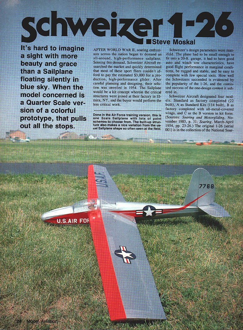
It's hard to imagine a sight with more beauty and grace than a sailplane floating silently in blue sky. When the model concerned is a quarter-scale version of a colorful prototype, that pulls out all the stops.
After World War II, soaring enthusiasts across the nation began to demand an all-around, high-performance sailplane. Sensing this demand, Schweizer Aircraft researched the market and quickly determined that most sport fliers couldn't afford the estimated $3,000 for a production, high-performance glider. After careful planning and designing, their solution was unveiled in 1954. The sailplane would be a kit concept wherein the critical structures were joined at the factory in Elmira, NY, and the buyer would perform the less-critical work.
Schweizer's design parameters were manifold. The plane had to be small enough to fit into a 20-ft. garage, it had to have good auto and winch tow characteristics, good flight performance in marginal conditions, be rugged and stable, and be easy to complete with few special tools. How well the Schweizers succeeded is evidenced by the popularity of the 1-26 and the continued success of the one-design contest it ushered in.
Schweizer Aircraft designated four models:
- Standard: factory completed (22 built)
- A: Standard kits (114 built)
- B: factory completed with all-metal-covered wings
- C: B version in kit form
(Sources: Soaring and Motorgliding, November 1983, p. 31; Soaring, March–April 1954, pp. 23–26.) The original 1-26 (serial 001) is in the collection of the National Soaring Museum.
Why I Selected the 1-26
Just as the full-sized subject has much to offer, the 1/4-scale model follows the aforementioned Schweizer principles—compactness, ruggedness, and simplicity. You can easily modify the model into any of the three types simply by adding sheeting where necessary. If you prefer the look of a stick model over one of the fiberglass "screamin' sausages," then this airplane is for you.
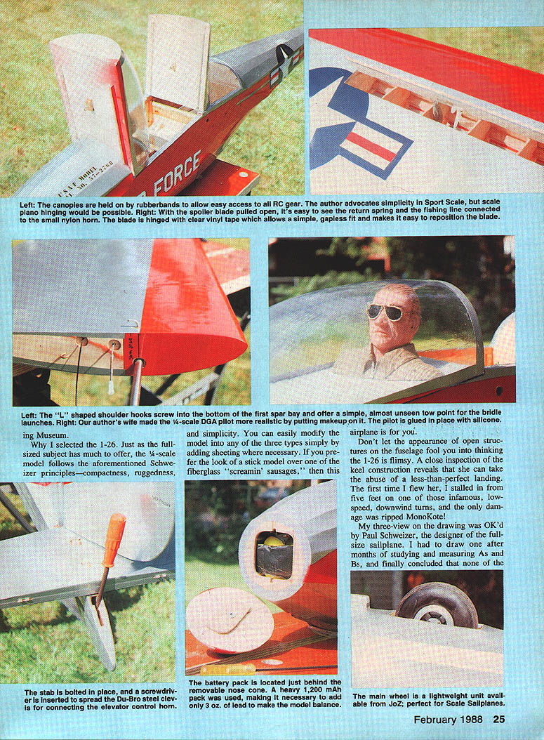
Don't let the appearance of open structures on the fuselage fool you into thinking the 1-26 is flimsy. A close inspection of the keel construction reveals that she can take the abuse of a less-than-perfect landing. The first time I flew her, I stalled in from five feet on one of those infamous low-speed, downwind turns, and the only damage was ripped MonoKote!
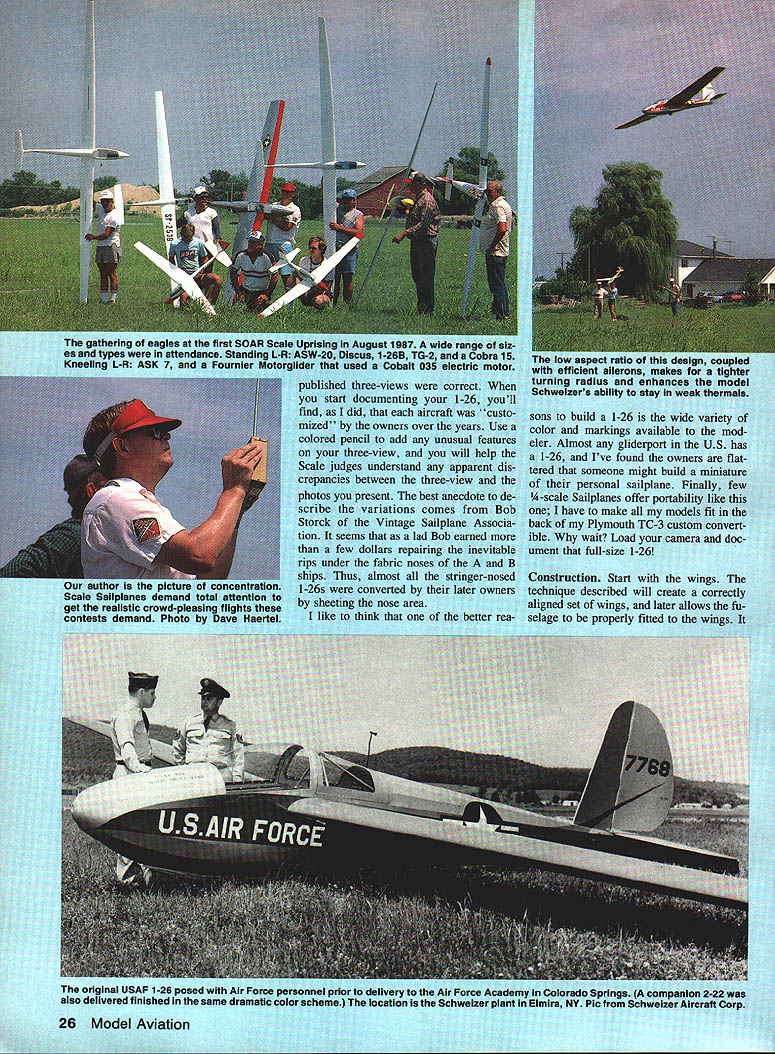
My three-view on the drawing was OK'd by Paul Schweizer, the designer of the full-size sailplane. I had to draw one after months of studying and measuring As and Bs, and finally concluded that none of the published three-views were correct. When you start documenting your 1-26, you'll find, as I did, that each aircraft was "customized" by the owners over the years. Use a colored pencil to add any unusual features on your three-view, and you will help the scale judges understand any apparent discrepancies between the three-view and the photos you present.
An anecdote from Bob Storck of the Vintage Sailplane Association: as a lad Bob earned money repairing the inevitable rips under the fabric noses of the A and B ships. Thus, almost all the stringer-nosed 1-26s were converted by later owners by sheeting the nose area.
One of the better reasons to build a 1-26 is the wide variety of color and markings available to the modeler. Almost any gliderport in the U.S. has a 1-26, and I've found owners are flattered that someone might build a miniature of their personal sailplane. Finally, few 1/4-scale sailplanes offer portability like this one; I have to make all my models fit in the back of my Plymouth TC-3 custom convertible. Why wait? Load your camera and document that full-size 1-26!
Construction
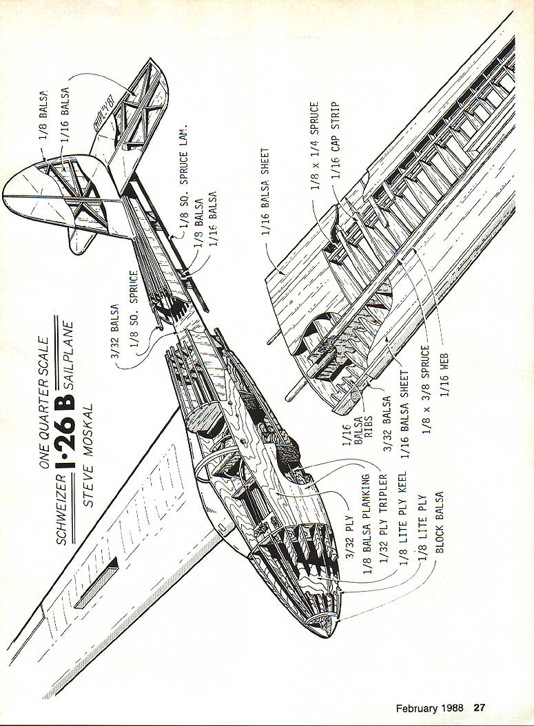
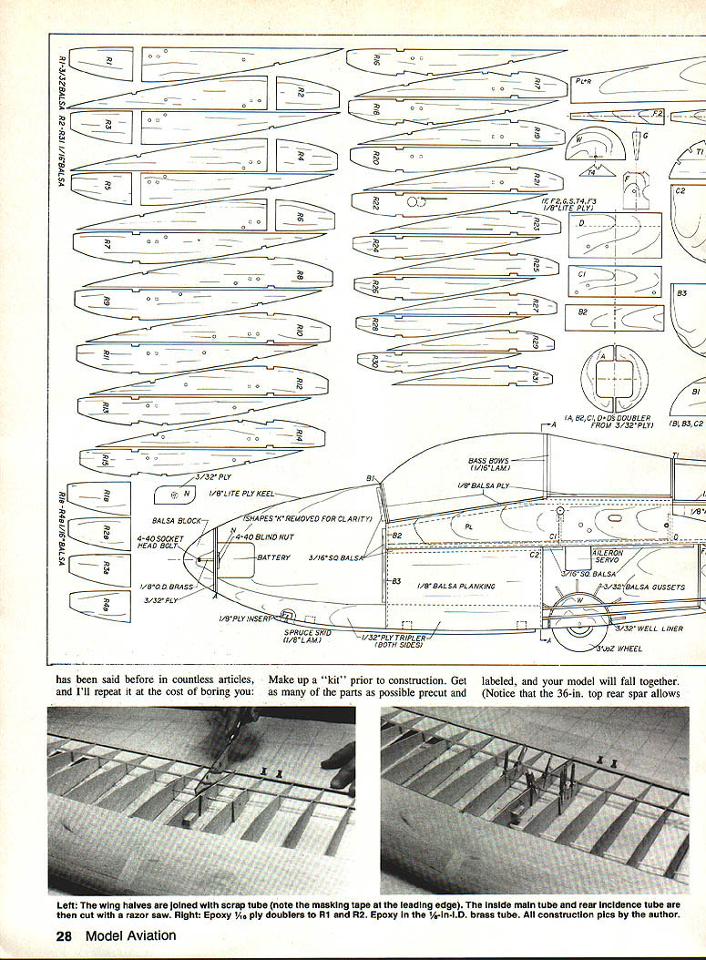
Start with the wings. The technique described will create correctly aligned wings and later allows the fuselage to be properly fitted to the wings. Make up a "kit" prior to construction: get as many parts as possible precut and labeled, and your model will fall together. Notice that the 36-in. top rear spar allows you to sheet to 75% of chord as in the A model. Finally, select medium balsa for the ribs and the best contest-grade balsa you can find for the sheeting and all other parts. I can't stress enough the need to build light—it's the secret to success with this low wing-loading sailplane.
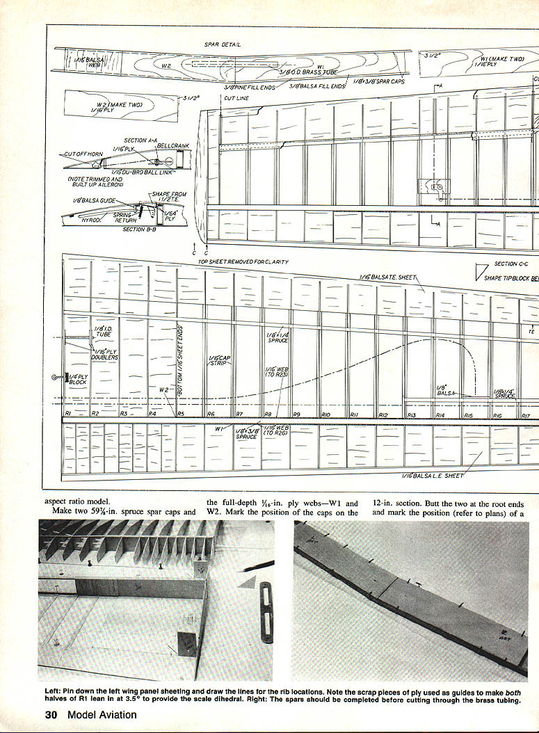
Wing structure and spars
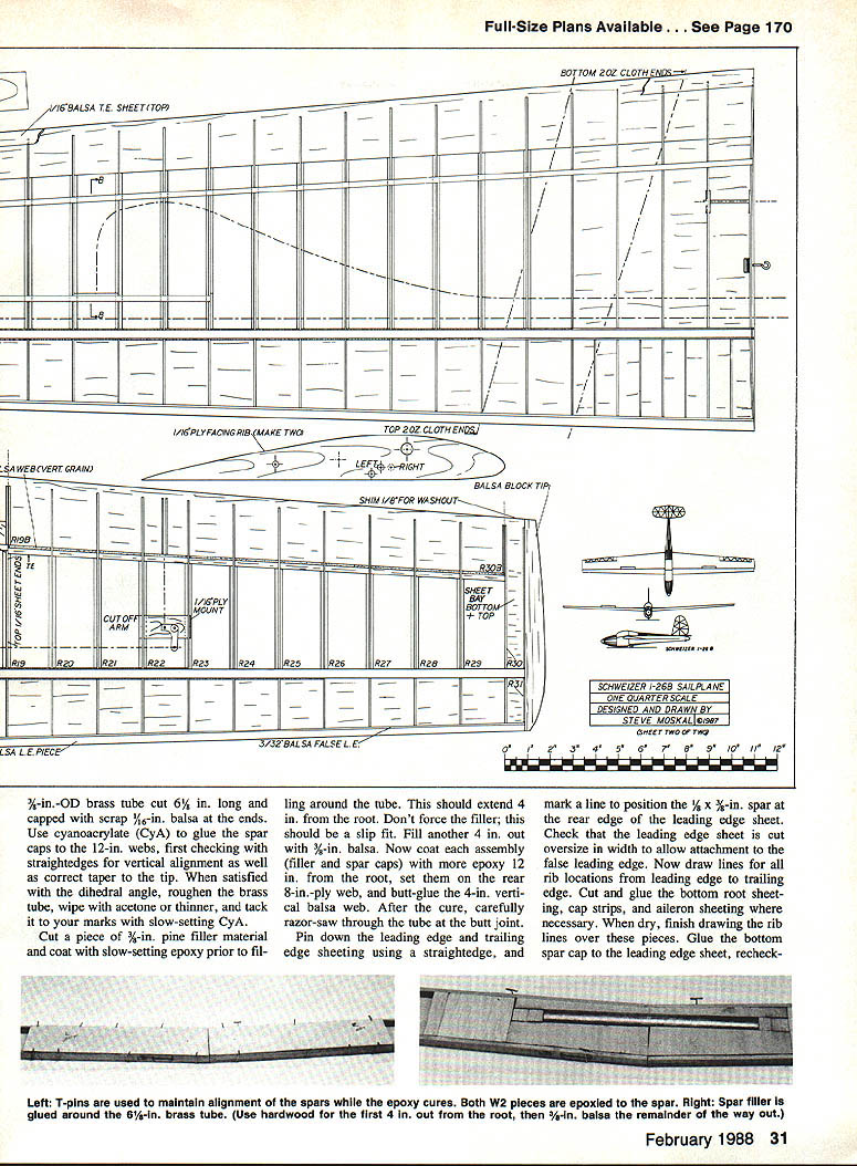
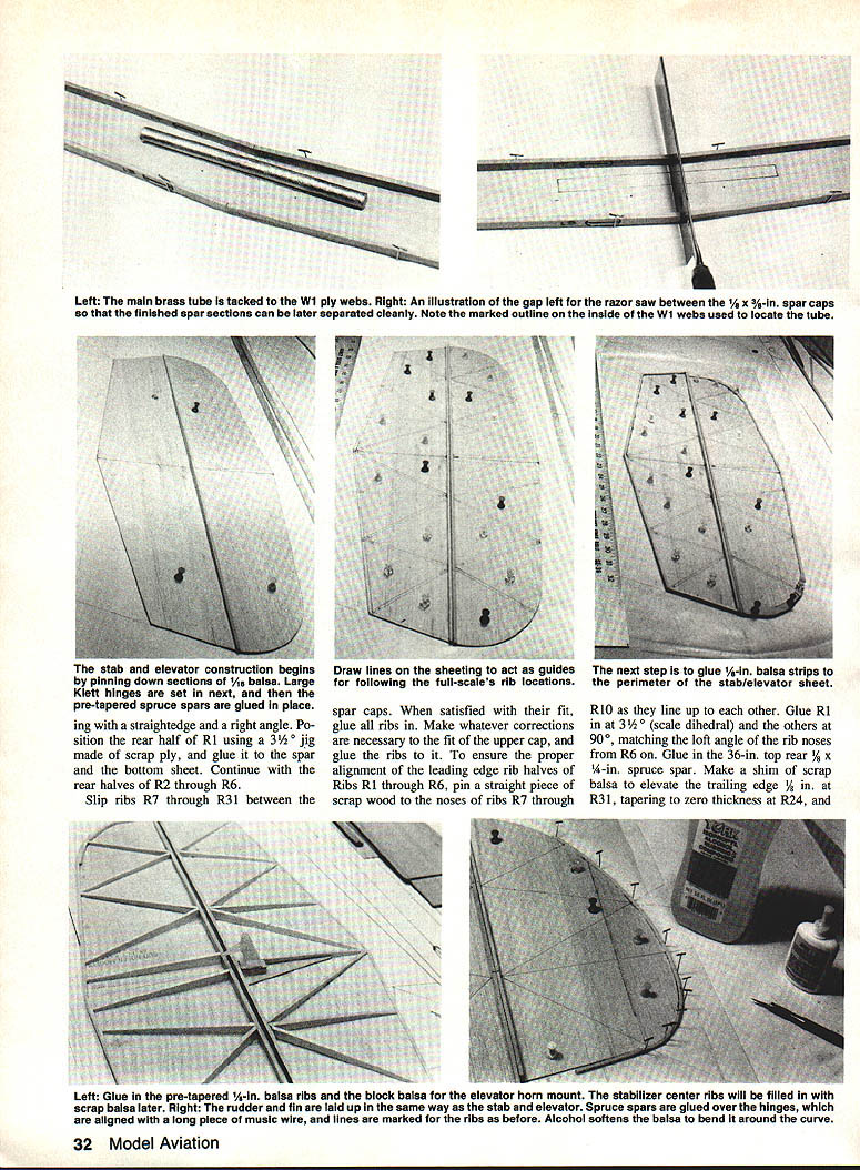
This is a high-aspect-ratio model. Make two 5/8-in. spruce spar caps and the full-depth 1/16-in. ply webs—W1 and W2. Mark the position of the caps on the 12-in. section. Butt the two at the root ends and mark the position (refer to plans) of a 3/8-in.-OD brass tube cut 6-1/2 in. long and capped with scrap 3/8-in. balsa at the ends.
Use cyanoacrylate (CyA) to glue the spar caps to the 12-in. webs, first checking with straightedges for vertical alignment as well as correct taper to the tip. When satisfied with the dihedral angle, roughen the brass tube, wipe with acetone or thinner, and tack it to your marks with slow-setting CyA.
Cut a piece of 3/8-in. pine filler material and coat with slow-setting epoxy prior to filling around the tube. This should extend 4 in. from the root. Don't force the filler; this should be a slip fit. Fill another 4 in. out with 3/8-in. balsa. Now coat each assembly (filler and spar caps) with more epoxy. Set them on the rear 8-in. ply web, and butt-glue the 4-in. vertical balsa web. After the cure, carefully razor-saw through the tube at the butt joint.
Pin down the leading edge and trailing edge sheeting using a straightedge, and mark a line to position the 1/8 x 3/8-in. spar at the rear edge of the leading-edge sheet. Check that the leading-edge sheet is cut oversize in width to allow attachment to the false leading edge. Now draw lines for all rib locations from leading edge to trailing edge. Cut and glue the bottom root sheeting, cap strips, and aileron sheeting where necessary. When dry, finish drawing the rib lines over these pieces. Glue the bottom spar cap to the leading-edge sheet and recheck alignment.
Position the rear half of R1 using a 3/32-in. jig made of scrap ply and glue it to the spar and the bottom sheeting. Continue with the rear halves of R2 through R6. Slip ribs R7 through R31 between the spar caps. When satisfied with their fit, glue all ribs in. Make whatever corrections are necessary to the fit of the upper cap, and glue the ribs to it.
To ensure the proper alignment of the leading-edge rib halves of R1 through R6, pin a straight piece of scrap wood to the noses of ribs R7 through R31 between the spar caps.
Glue 1/4-in. balsa strips to the perimeter of the stab/elevator sheet. Glue R10 as they line up to each other. Glue R1 at the scale dihedral (3/32 in.) and the others at 90°, matching the loft angle of the rib noses from R6 on. Glue in the 36-in. top rear 1/8 x 1/4-in. spruce spar. Make a shim of scrap balsa to elevate the trailing edge 1/8 in. at R31, tapering to zero thickness at R24, and slip this underneath.
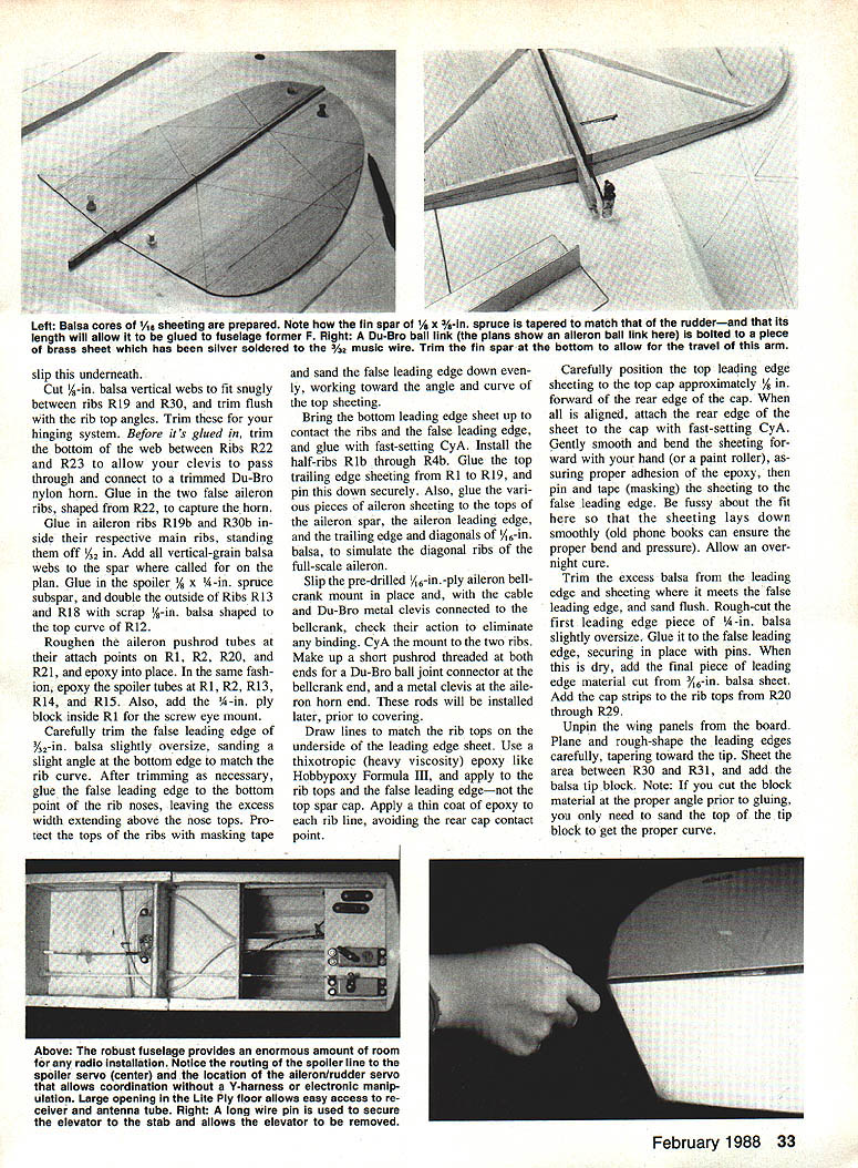
Cut 1/16-in. balsa webs to fit snugly between ribs R19 and R30, and trim flush with the rib top angles. Trim these for your hinging system. Before it's glued, fit in the bottom of the web between ribs R22 and R23 to allow your clevis to pass through and connect to a trimmed Du-Bro nylon horn. Glue in the two false aileron ribs, shaped from R22, to capture the horn.
Glue in aileron ribs R19b and R30b inside their respective main ribs, standing them off 5/32 in. Add all vertical-grain balsa webs to the spar where called for on the plan. Glue in the spoiler sub-spar, and double the outside of ribs R13 and R18 with scrap 1/8-in. balsa shaped to the top curve of R12.
Roughen the aileron pushrod tubes at their attach points on R1, R2, R20, and R21, and epoxy into place. In the same fashion, epoxy the spoiler tubes at R1, R2, R13, R14, and R15. Also, add the 1/4-in. ply block inside R1 for the screw-eye mount.
Carefully trim the false leading edge of 3/32-in. balsa slightly oversize, sanding a slight angle at the bottom edge to match the rib curve. After trimming as necessary, glue the false leading edge to the bottom point of the rib noses, leaving the excess width extending above the nose tops. Protect the tops of the ribs with masking tape and sand the false leading edge down evenly, working toward the angle and curve of the top sheeting.
Bring the bottom leading-edge sheet up to contact the ribs and the false leading edge, and glue with fast-setting CyA. Install the half-flos rib through R40. Glue the top trailing-edge sheeting from R1 to R19, and pin this down securely. Also glue the various pieces of aileron sheeting to the tops of the aileron spar caps, the aileron leading edge, and the trailing edge and diagonals of 1/16-in. balsa to simulate the diagonal ribs of the full-scale aileron.
Slip the pre-drilled 1/16-in.-ply aileron bellcrank mount in place and, with the cable and Du-Bro metal clevis connected to the bellcrank, check their action to eliminate any binding. CyA the mount to the two ribs. Make up a short pushrod threaded at both ends for a Du-Bro ball-joint connector at the bellcrank end and a metal clevis at the aileron horn end. These rods will be installed later, prior to covering.
Draw lines to match the rib tops on the underside of the leading-edge sheet. Use a thixotropic (heavy-viscosity) epoxy like Hobbypoxy Formula III, and apply to the rib tops and the false leading edge — not the top spar cap. Apply a thin coat of epoxy to each rib line, avoiding the rear cap contact point.
Carefully position the top leading-edge sheeting to the top cap approximately 1/16 in. forward of the rear edge of the cap. When all is aligned, attach the rear edge of the sheet to the cap with fast-setting CyA. Gently smooth and bend the sheeting forward with your hand (or a hot roller), assuring proper adhesion of the epoxy, then pin and tape (masking) the sheeting to the false leading edge. Be fussy about the sheeting so that it lays down smoothly (old phone books can ensure the proper bend and pressure). Allow an overnight cure.
Trim the excess balsa from the leading edge and sheeting where it meets the false leading edge, and sand flush. Rough-cut the first leading-edge piece of 1/8-in. balsa slightly oversize. Glue it to the false leading edge and secure with pins. When dry, sand the piece to the proper leading-edge profile and add the cap strips to the rib tops from R20 through R29.
Unpin the wing panels from the board. Plane and rough-shape the leading edges carefully, tapering toward the tip. Sheet the area between R30 and R31, and add a balsa tip block. Note: If you cut the block material at the proper angle prior to gluing, you only need to sand the top of the tip block to get the proper curve.
Remove the aileron cables and join the panels with a small piece of 1/32-OD brass tube so that the root ribs are flush to each other. Lay one section down flat and block up the other section about mid-panel. Roughen a 5/16-in.-ID brass tube cut 4-1/4 in. long, seal the ends with scrap balsa, and clean with a solvent. Separate the panels, and slip the tube through the ribs and six of the pre-drilled 1/16-in. ply doublers. When the root ribs are aligned to each other, pin each one so that the leading and trailing edges match. Take your time and correct the holes in the ribs and doublers where necessary to get an unforced fit. Coat the doublers with a thin layer of slow-cure epoxy and clamp to the ribs, building a small fillet of epoxy at the inside joints. After these cure, cut through the tube carefully with your razor saw as before. Reposition the wings with washout shims in place, pin securely, and complete the top sheeting and cap strips.
Spoilers and ailerons
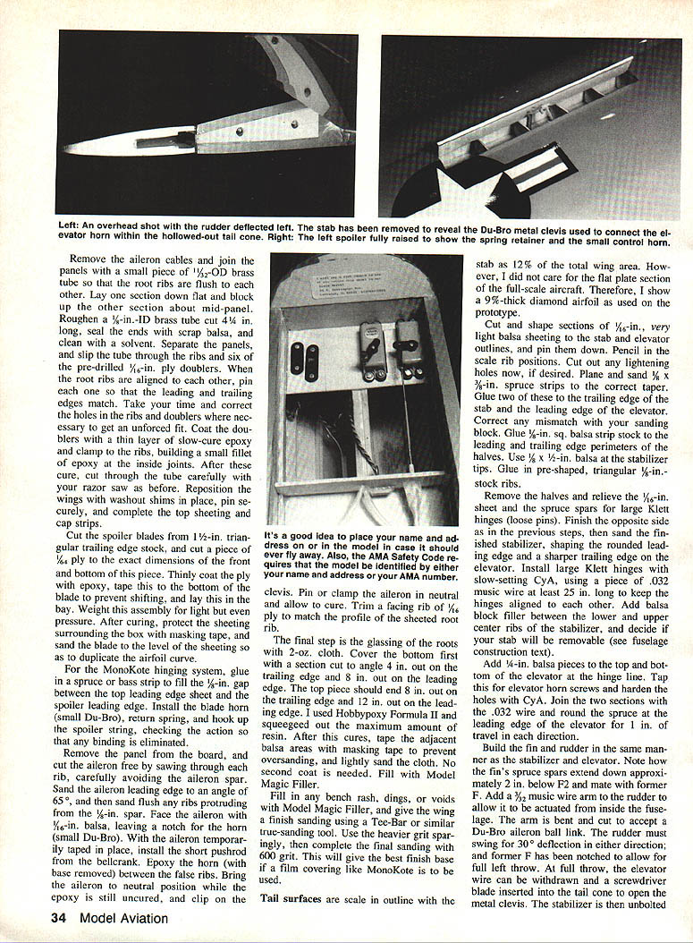
Cut the spoiler blades from 1-1/2-in. triangular trailing-edge stock, and cut a piece of 1/4-in. ply to the exact dimensions of the front and bottom of this piece. Thinly coat the ply with epoxy, tape this to the bottom of the blade to prevent shifting, and lay this in the bay. Weight this assembly for light but even pressure. After curing, protect the sheeting surrounding the box with masking tape, and sand the blade to the level of the sheeting so as to duplicate the airfoil curve.
For the MonoKote hinging system, glue in a spruce or bass strip to fill the 1/8-in. gap between the top leading-edge sheet and the spoiler leading edge. Install the blade horn (small Du-Bro), return spring, and hook up the spoiler string, checking the action so that any binding is eliminated.
Remove the panel from the board, and cut the aileron free by sawing through each rib, carefully avoiding the aileron spar. Sand the aileron leading edge to an angle of 65°, and then sand flush any ribs protruding from the 1/8-in. spar. Face the aileron with 1/16-in. balsa, leaving a notch for the horn (small Du-Bro). With the aileron temporarily taped in place, install the short pushrod from the bellcrank. Epoxy the horn (with base removed) between the false ribs. Bring the aileron to neutral position while the epoxy is still uncured, and clip on the clevis. Pin or clamp the aileron in neutral and allow to cure. Trim a facing rib of 1/16 ply to match the profile of the sheeted root rib.
Root glassing and finishing
The final step is the glassing of the roots with 2-oz. cloth. Cover the bottom first with a section cut to angle 4 in. out on the trailing edge and 8 in. out on the leading edge. The top piece should end 8 in. out on the trailing edge and 12 in. out on the leading edge. I used Hobbypoxy Formula II and squeegeed out the maximum amount of resin. After this cures, tape the adjacent balsa areas with masking tape to prevent oversanding, and lightly sand the cloth. No second coat is needed. Fill with Model Magic Filler.
Fill in any bench rash, dings, or voids with Model Magic Filler, and give the wings a final sanding using a Tee-Bar or similar flat sanding block. Use the heavier grit sparingly, then complete the final sanding with 400 grit. This will give the best finish base if a film covering like MonoKote is to be used.
It's a good idea to place your name and address on or in the model in case it should ever fly away. Also, the AMA Safety Code requires that the model be identified by either your name and address or your AMA number.
Tail Surfaces
The tail surfaces are scale in outline with the stabilizer as 12% of the total wing area. However, I did not care for the flat-plate section of the full-scale aircraft. Therefore, I show a 9%-thick diamond airfoil as used on the prototype.
Cut and shape sections of 1/8-in. very light balsa sheeting to the stabilizer and elevator outlines, and pin them down. Pencil in the scale rib positions. Cut out any lightening holes now, if desired. Plane and sand 1/32-in. spruce strips to the correct taper. Glue two of these to the trailing edge of the stabilizer and the leading edge of the elevator. Correct any mismatch with your sanding block. Glue 1/8-in. sq. balsa strip stock to the leading and trailing edge perimeters of the halves. Use 1/8 x 1/2-in. balsa at the stabilizer tips. Glue in pre-shaped triangular 1/8-in. stock ribs.
Remove the halves and relieve the 1/8-in. sheet and the spruce spars for large Kley (loose pin) hinges. Finish the opposite side in the previous steps, then sand the finished stabilizer, shaping the rounded leading edge and a sharper trailing edge on the elevator. Install large Kley hinges with a light slow-setting CyA, using a piece of .032 music wire as a guide to keep the hinges aligned to each other. Add balsa block filler between the lower and upper center ribs of the stabilizer, and decide if your stab will be removable (see fuselage construction).
Add 1/4-in. balsa pieces to the top and bottom of the elevator at the hinge line. Tap in the elevator horn screws and harden the holes with CyA. Fit a 3/32-in. music wire arm to the rudder to allow it to be actuated from inside the fuselage. The arm is bent and cut to accept a Du-Bro aileron ball link. The rudder must swing for 30° deflection in either direction; former F-3 has been notched to allow full left throw. At full throw, the elevator is limited to allow a screwdriver blade to be inserted into the tail cone to open the metal clevis. When this is done, unbolt the clevis.
Fuselage
Begin the box sides by trimming and joining 1/16-in. balsa sheet and 1/16-in. ply over the outline on the wax-paper-covered plan. Use ply from B2 to D, then proceed aft with 1/16-in. balsa (of the lightest weight), making sure that the grain runs vertically. Glue 1/8 x 1/4-in. spruce strips to the perimeter of this section. Remove from the wax paper and complete a right side.
Fill in the space between the spruce longerons from B2 to D with 1/8-in. Lite Ply (shape F2). Using Formula II, epoxy the 3/32-in. ply pieces PL and PR to the spruce strips where the parts touch the Lite Ply and the spruce, except for the lower longeron area aft of former D. When cured, carefully align and tape the two sections together, then drill a 3/32-in. hole for the main tube and 1/16-in. holes for the rear incidence and spoiler tubes.
Separate the two sections, and drill the respective 7/64-in. aileron cable holes. Route out openings for the servo cables. Drill through C1 and D for the elevator cable tube, then separate and drill the rudder cable tube hole in D and the spoiler tube holes in C1.
Mark the inside surface of the two fuselage box sides for 1/8 x 1/4-in. spruce doublers, leaving gaps for B2 and C1 and stopping at D. Cut the strips and glue to the inside, noting that the bottom strips are raised 3/32 in. to allow the later addition of the box floor.
Glue in B2, C1, and D, using right triangles to check the squareness of formers to the side and of the sides to the building board. When satisfied, clamp the sides together.
Epoxy a doubler and a tripler cut from 1/8 x 3/32-in. spruce flush to the top of C1, and glue 1/8 x 1/4-in. spruce to the joints aft of B2, on either side of C1 and forward of D. The tripling of the area on top of C1 will allow more surface on which to secure the 3/32-in. brass tube.
Do not epoxy the brass tubes until you are satisfied with the wing alignment. Wings should easily slip on both the main rod (1/8-in. drill rod, tempered Rockwell C-Scale 42–45) and the incidence-setting rod. If not, use only the incidence tube hole as necessary. Brush on Formula II, then add medium-weight glass cloth over both tubes, contacting their respective formers and box sides.
Cut a rectangle of 3/32-in. ply for a servo tray aft of B2, with cutouts for your servos and switch harness. The rest of the box floor will be formed from 3/32-in. balsa, with the grain running side to side. I used a small piece of 3/32-in. ply cut out for my aileron servo aft of C1, then continued with 3/32-in. balsa to E. Flip the box over and mark a centerline on the bottom from B2 to D. Glue on square strips of 3/16-in. balsa on either side of the line and corresponding to the 1/16-in. thickness of the keel. Trial-fit the Lite Ply keel with servos in place, and with an eye toward routing wires for your airborne system. Make any cutouts for them now. I left a 3/16-in. gap in the floor aft of my ply tray with no apparent loss in strength.
The battery goes behind former A (1.2 Ah pack recommended). Trim the keel for your pack, leaving some space for foam also.
After B1 is cut, trace a duplicate in balsa ply for use on the forward canopy tray. Also trace a one-piece copy of former A in 3/32-in. aircraft ply. Make up the 1/8-in. balsa ply pieces epoxied together at right-angle edges. The secret is in the gentle heating of the epoxy with a heat gun so that it flows and will spread thinly over the sheet.
Cut out turtledeck formers T1 through T3 from 1/8-in. balsa. T4 is cut from Lite Ply. Notching should be done after they're glued in place. Decide at this point if your subject is to be stringered or sheeted in that area, and whether the turtledeck is to be sheeted. Trim the formers in those areas to allow for your sheet and planking material.
Steady the box on your bench and slip the wings on the rods, checking for fit to PL and PR. Use straightedges to keep the sides square, and use pins in the board to keep PL against the fuselage. Glue in T4 and F4, aligning the center of F to points equidistant on the wing trailing edges. Mount the fin platform F2, and true the fin with a right triangle. Set the fin aside, and epoxy F2 to T4 and F.
Fit the stab mount S and epoxy it in now. Line the stab up on the fuselage centerline, and tack glue to S. Drill the two holes for your 1/4-in. mounting bolts through the stab block in the stab and S. Countersink them into the balsa to allow the bolt heads to sit flush with the top of the stab. Lubricating the bolts with Vaseline, put them through the stab and snug up the nuts. When satisfied with the stab's alignment, run a bead of slow-cure CyA around the nut rims where they touch the underside of the mount.
Glue in scrap, standing the tail ends of PL and PR away from the gentle bend of the fuselage sides and flush to the root ribs. Glue a 1/4-in. spruce dowel from PL and PR to approximately 1/2 in. aft of F.
Install the tubes for your elevator and aileron servo cables, securing them at the formers with epoxy and a small patch of medium-weight glass cloth. This is critical in keeping the tubes from bending and popping away from the formers under flight loads. What we can get away with in small gliders is woefully inadequate in quarter-scale models. Notch the turtledeck formers to receive 1/8 x 1/4-in. spruce longerons. Round the top edges of the longerons prior to gluing.
Make up the keel and epoxy in 1/8-in. ply inserts to receive the brass wood screws used for mounting the skid. Glue in the keel, and key this piece with 3/16-in. balsa strips where it touches B1, B2, and B3. Glue in former halves of A, B3, and C2. Laminate the keel with 1/8-in. ply on either side of the skid mounting area.
To save weight, I used a 3-in. ultralight wheel from JoZ Products. The well liner is 3/32-in. balsa wetted slightly to allow the bend. Glue it in, then glue 3/32-in. triangular balsa gussets to brace it to the keel. After rounding the outer edges, glue the first two horizontal ply nose formers that will simulate the tubing from B2 to A. You should be able to use two pieces of 1/16-in. balsa sheet per side to plank between B3 and C2. Glue in doubler strips of balsa to the keel flush to the bottom of B3 and C2 as planking support. Do the same where the planking will touch PL and PR. After planking, add the rest of the Lite Ply shapes from B3 to A. Glue in B1, and finish the formers from B1 to A.
Nose and canopy
Cut the canopy trays carefully from 1/16-in. balsa ply, and begin work on the front canopy by fitting up the balsa ply former you prepared to match B1. Shape the rear bow of this tray by laminating two pieces of 1/16-in. balsa, about 3/32-in. thick, over a former. Trial-fit the bow to the tray after notching the two rear corners, and glue it in when satisfied. The rear tray is the reverse of this, with the aft shape matching T1 and the forward shape of laminated balsa matching the front bow. Finish the trays with two coats of Formula II epoxy, and paint with a flat gray epoxy enamel. This provides the best surface for gluing on the canopy with Wilhold's RC-56.
Plan your instrument panel (if any) and pilot—a DGA quarter-scale bust is what I chose because of its light weight. The 1-26 had a steel-tube rollover structure under the rear canopy. I used Sullivan's outer sleeves to simulate this—drinking straws would work just as well. Cover the glue joints where the canopy trays touch the trays and bows with strips of painted plastic to simulate the aluminum framework. The rear canopy is a clear acetate sheet, while the forward canopy is molded from a piece of plastic clamped in a frame, heated in an oven, and drawn over a wooden plug. This method has been described many times in other articles—one of the best being by Steve Gray in the March 1987 issue of Model Builder. For those who would rather not make the canopy, they are available ready-made from Shabo Scale, 2416 North 66th, Wauwatosa, WI 53213. Plan your canopy hold-downs—rubber bands and miniature hooks are the simplest and lightest.
Route a pair of inner Nyrods from PL and PR to the spoiler servo, and glue them in. Install all the airborne gear and check all actions, correcting for binding and rubbing if any. Complete the turtledeck structure, and add a cross-grain floor of 1/16-in. balsa from E to G.
Glue in both halves of F3 and the 1/8-in. balsa lower main stringer standoffs. Laminate the lower main stringer from two pieces of 1/8-in. sq. spruce. Glue the standoffs to the 1/16-in. floor of the fuselage, then glue the stringer to these, running from the keel to G. Glue in 1/8-in. balsa gussets to brace the standoffs to the floor. Add a piece of 3/32-in. spruce, doubling the top longeron from T1 and tapering aft of F. Complete the two lower stringers running from C2 to F3, and aft of F3 to the keel.
Form the skid from two pieces of 1/8 x 1/2-in. spruce, laminating them with a form made from common nails in a board. Drill the skid for the screw attach points, then remove it, cover with glass cloth, and paint to match your scheme. Some 1-26 aircraft had a fabric fairing to cover the gap between the skid and the fuselage, but quite often no fairing was used.
The tail and nose cone are built up from balsa. Shape the tail cone from a 1/4-in. core of Lite Ply to hold the shape. This ply core is doubled with 1/16-in. balsa, which is carved to the correct taper. Tack-glue this to the fuselage, and check for maximum travel on the elevator horn. It will later be glued on after painting or covering.
I carefully drilled the center of the nose cone (after shaping it from soft balsa on the 3/32-in. ply disc which matches former A) for a 4-40 hex head bolt. I eased in a piece of 1/16-in. brass tube to be used as a bushing. I then created an "N" shape from 3/32-in. ply that would slip in behind A, and drilled it for a 4-40 blind mounting nut. This holds the nose cone in place when the bolt is tightened. The access hole to the 4-40 bolt serves as the scale air vent common to all 1-26 nose cones. (My battery pack, by the way, also has the advantage of being accessible and acts as a balancing weight.)
The nose cone assembly was glassed with 2-oz. cloth, covered with one coat of Formula II epoxy, and filled with Model Magic Filler.
Preparations for covering and final details
Now is the time to plan any unique details particular to your subject prior to covering. If you've ever covered a rubber-powered model with silkspan-and-dope, the approach to this fuselage is the same, except you'll no doubt want to use a heat-shrink covering as I did. The easiest way to cover the stringered nose is to cut each triangular section oversize and, starting from the top of the keel, work downwards section by section—one large piece won't work here. The rest of the fuselage can be done in three segments: stringered turtledeck first, then left and right sides down to the centerline.
Before covering, glue an inspection fairing of balsa at the rudder horn to provide access to the linkage if needed. The scale inspection cover is a balsa circle covered with MonoKote and tack-glued to the fairing after final covering. Mount all the gear, including the main and tail wheel (Perfect 1/2-in.), and balance the model at the indicated safe point. Install the radio and the flying surfaces, then check the action of all controls. Your rudder should have a maximum of 30° deflection either way. The elevator should need only 1/2-in. maximum throw up or down, and the ailerons should have a minimum differential of 3:1—that is, three up to one down. The spoilers need a maximum throw of 45° and are extremely effective when fully open. Epoxy the fin to F and F2 after the fuselage is covered, and connect the linkage; then glue on the inspection hatch.
Balancing
The mean aerodynamic chord (MAC) calculation (see Brad Powers' article in Model Aviation, May 1980) has always resulted in the proper balance of my sailplanes. I've calculated all this for you on the 1-26: the MAC is 12 15/16 in. This translates to 30% of the MAC measured on the root rib. This is the safe balance point for the model.
My experience with a previous mid-wing glider is that the bridle launch is very safe (even if one of the rings falls off in mid-launch), and allows maximum rotation on launch. Balance the plane prior to covering, adding weight as far forward as possible to minimize all-up weight. Careful selection of materials and glue should result in an uncovered airframe balancing at 30% of the mean aerodynamic chord, as was the case in my prototype.
Covering and Marking
I used Super MonoKote because of my desire to keep things light, and MonoKote trim sheets for the large letters. Duplicating the national insignia was made easy by using Sig's sticker-on decals—luckily the smaller size on the sheet was perfect scale. The smaller military nomenclature letters ("NO PUSH," "LIFT HERE," etc.) were vinyl rub-ons. After some experimentation, I found these work best rubbed onto a small section of MonoKote which is then placed in position, covered with wax paper, and sealed with the iron at a low temperature slightly below the EconoKote range.
You'll notice the red "flash" running from nose to tail. This was stock red K&B Superpoxy paint sprayed on the MonoKote after wiping it clean with acetone and masking the pattern.
Install a steel shoulder hook from the hardware store in each root about 1/2 in. to the rear of the fuselage sides. Remove the hooks and harden the tapped hole with CyA so that the hooks will be removable for display or judging. Install the main wheel by cutting a small hole in the MonoKote on one side opposite the axle hole. Slip in the brass tube axle, securing it with a dab of epoxy. Now patch the MonoKote.
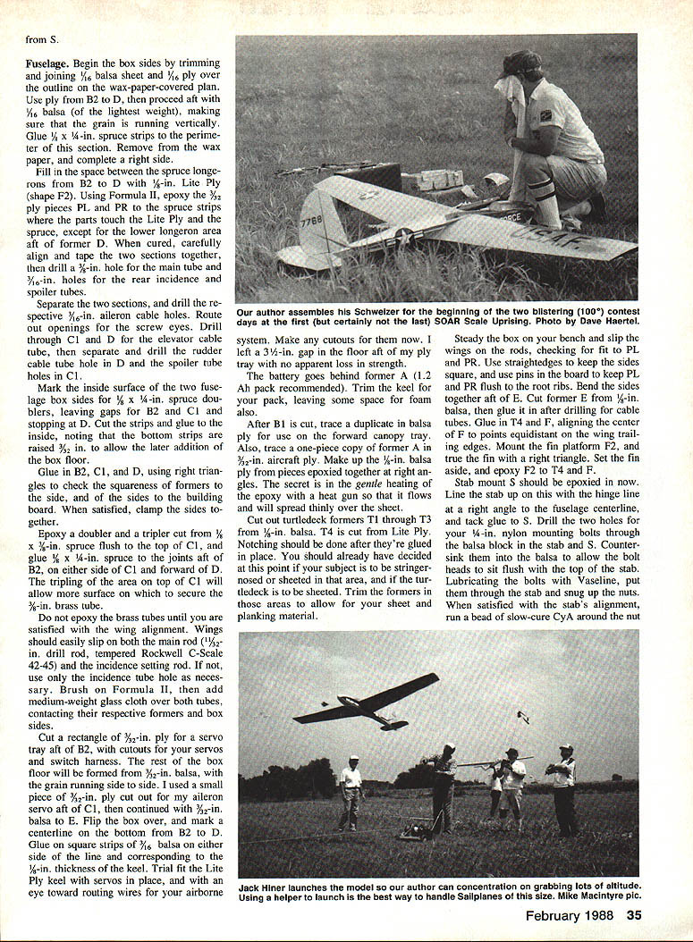
Make up a bridle of at least 100-lb.-test braided nylon, and choose a partner with experience launching large sailplanes. Have him or her hold the model with the left hand cupped in front of the left leading edge and the right hand at about T3 on the fuselage. On first flights, launch straight forward and, after gaining flying speed, rotate gently up.
Transcribed from original scans by AI. Minor OCR errors may remain.

