
SARPI*
John W. Powell
Simple Auditory Receiver Performance Indicator
Since the days of crystal sets, it has been known that the best way to tell if a radio receiver works properly is to listen to it. This idea came to me after several years of frustrating attempts to tune and range-check RC receivers using the recommended methods.
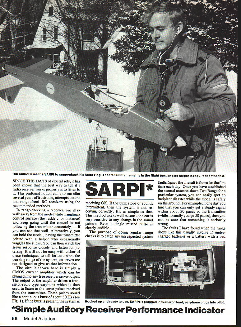
In range-checking a receiver, one common method is to walk away from the model while waggling a control surface (the rudder, for instance), and keep going until the control no longer follows the transmitter accurately—if you can see that well. Alternatively, you can hold the model while the transmitter is left with a helper who occasionally waggles the sticks. You can then watch the servo response closely and listen for jittering. It will not be easy with either of these techniques to tell for sure what the working range of the system is, because servos are not designed to give us that information.
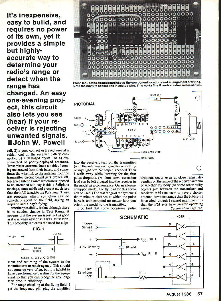
The circuit shown here is simply a CMOS current amplifier which can be plugged into any free receiver servo output. The output of the amplifier drives a transistor-radio-type earphone which is then used to listen to the servo pulses received from the transmitter. These pulses sound like a continuous buzz of about 50 Hz (see Fig. 1). If the buzz is present, the system is receiving OK. If the buzz stops or sounds intermittent, then the system is not receiving correctly. It's as simple as that. This method works well because the ear is very sensitive to any change in the sound pattern. Even a single missed pulse is clearly audible.
The purpose of doing regular range checks is to catch any unsuspected system faults before the aircraft is flown for the first time each day. Once you have established the normal antenna-down Test Range for a particular system, you can easily spot an incipient problem while the model is safely on the ground. For example, if one day you find that you can only get a steady signal within about 30 paces of the transmitter (while normally you go 50 paces), then you can be sure that something is seriously wrong.
The faults I have found when the range drops like this usually involve:
- undercharged batteries or a battery with a bad cell
- poor contact, frayed wire, or a bad solder joint or receiver battery connector
- damaged crystal
- disconnected or poorly deployed antennas
Transmitter antennas have a habit of coming unscrewed from their bases; sometimes a wire-link antenna or the transmitter circuit board gets broken off. Receiver antenna wires, expected to be stretched out (for example inside a sailplane fuselage), can come adrift or be much shorter than intended. RF signal problems often can be subtle; regular checks can save expensive airplane damage. Another possibility is that a system that was fine when new last season may now indicate a need for alignment even if no sudden change in Test Range appears.
It's inexpensive, easy to build, and requires no power of its own, yet SARPI provides a simple but highly accurate way to determine your radio's range or detect when the range has changed. An easy one-evening project, this circuit also lets you hear if your receiver is rejecting unwanted signals.
FIG. 1 — Signal at a servo output
- Typical levels: 4.8 V (high) and 0 V (low)
- Typical pulse width: 1–2 ms
- Typical repetition: 20 ms (about 50 Hz)
Schematic (overview)
- Servo signal in → CMOS buffer (4049 or 4050) → earphone jack
- Powered from the receiver's battery (no separate power required)
- 10 µF capacitor for decoupling
- Small series resistor (e.g., 100 Ω) may be used to limit current to the earphone
The earphone method can also serve as a quick reference check of system operation after a "hard-landing incident" (crash). This does not check the servos themselves, but servos are quickly tested by normal stick-waggling and inspection.
When sharing a flying site with other fliers using adjacent RC channels, it is helpful to have a non-destructive means of checking your system's sensitivity to interference. Using servos as the output indicator can be risky when interference pulses are received, since spurious commands can spin the servos and wrap pushrods and linkages into spaghetti. A safer technique is to disconnect all servos and use the SARPI instead. You can then experiment freely, listening at different distances from other fliers—and with your transmitter on or off, antenna down or up—without risking damage to your equipment.
Interference will change the steady buzz into a syncopated beat, and even some "static" noise may be heard.
Construction
The circuit requires a minimum of components, and they can all be found at Radio Shack stores, except for the servo lead which must be obtained from an RC dealer. Since most of us are not equipped to make PC boards, the circuit is shown wired on a small IC matrix board. For ease of assembly, as many links as possible are made with bare solid wire. Note that the wires must be positioned as shown in the pictorial to avoid shorts. I obtained small-gauge bare wire by stripping some heavy stranded hookup wire and using the individual strands.
Layout is not critical—except for avoiding shorts and solder bridges. All components are mounted on the silk-screened side of the board, not on the copper. Use an IC socket and observe the polarity of the 10 µF capacitor. Insert the IC in its socket with the correct orientation. When wiring the socket, put a dab of paint or a marker adjacent to Pin 1 on both sides of the board for later reference.
Care must be taken to establish the identity of the servo leads for your receiver. Although probably the worst that will happen with reversed connector wiring is loss of the 4049 (4050) IC, the circuit certainly won't work. On most sets, the servo leads are color-coded: red (+V), black (—V), and a third color for the signal lead. If the battery connector lead is similar to the servo leads, check the battery wiring with a voltmeter to find which pin is (+) and which is (—). World Engines and Airtronics leads are shown in Fig. 2 (not included here).
Construction sequence:
- Epoxy the 1/8-in. earphone socket to the top surface of the board in the position shown. You may also solder a retaining wire over the jack.
- Solder in the IC socket. Mark Pin 1 on both surfaces.
- Install the resistor and tantalum capacitor. The capacitor (+) lead must be oriented correctly.
- Install bare wire links, and dress them neatly.
- Make the remaining connections with insulated wire.
- Attach the servo lead to the appropriate pads. Put the IC in its socket.
Carefully check your wiring against the pictorial and the schematic before plugging the circuit into a receiver. When all is well, plug in the earphone and plug the SARPI into any servo socket of a receiver. Switch on the system. With the transmitter on, a steady loud buzz should be heard. With the transmitter off, there should be no sound. Note: with some FM receivers, it is normal to hear occasional single clicks with the transmitter off as the receiver picks up random noise.
The earphone method can also serve as a quick reference check of system operation after a "hard-landing incident" (crash).
Parts list (Radio Shack catalog numbers)
- Multipurpose bus board 276-150 — $0.79 ea.
- Type 4049 (or 4050) CMOS hex buffer IC 276-2449 — $1.19 ea.
- 16-pin DIP socket 276-1998 — $0.89/2
- Enclosed 1/8-in. jack socket 274-297 — $1.19/2
- 10 µF tantalum capacitor 272-1436 — $0.69 ea.
- Mono earphone with 1/8-in. plug 33-175 — $1.49 ea.
- Servo lead to suit RC system
- Hookup wire: small-gauge solid (e.g., 26 to 30), bare and insulated
SARPI is inexpensive, easy to build, requires no separate power source, and provides a quick, accurate way to monitor receiver performance and to detect changes in range or interference.
Transcribed from original scans by AI. Minor OCR errors may remain.

