
The Schuemann Wing
One of the latest advances to come from Germany is the Schuemann wing planform, used with impressive results on both full-size and model sailplanes. It significantly reduces drag and, because of its simple shape, can easily be duplicated on almost any wing.
There are pilots like Brian Agnew and Tom Brightbill who can max out with just the picture of a model sailplane. Meanwhile, the rest of us are still looking for that one special design that will magically turn us into top fliers. Traditionally this search has led to borrowing design features from Free Flight, from full-size aircraft, and from that nucleus of frustration and delight—F3B soaring. Today, the separate arenas of full-size sailplanes and F3B have come together to give us a clear design trend. Both the Discus Standard Class sailplane and the Epsilon model of F3B fame use the Schuemann wing planform. There are good reasons to investigate this configuration for yourself.
Adoption beyond sailplanes
Usage of the Schuemann wing hasn't been confined to sailplanes. Burt Rutan has designed two powered aircraft using this planform. One is a six-passenger plane called the Catbird, which features a winglet just behind the engine cowl, a Schuemann wing, and a T-tail. The other plane is an Unlimited Class racer that vaguely resembles the P-38 Lightning; it has two large engine pods connected by the wing and horizontal stab with a cockpit pod in the middle. The virtues of this wing shape are apparent in fast, clean, powered planes as well as on the Discus.
Where wing drag comes from
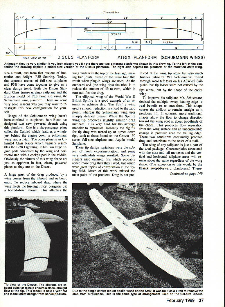
A large part of the drag produced by a wing comes from the inboard and outboard ends. To reduce inboard drag where the wing meets the fuselage, most designers use a bolted-down mount that attaches the wing flush with the top of the fuselage, making two joints instead of the usual four that result from plug-in wings. At the outboard end (the wingtips), the trick is to reduce the amount of lift to zero, which in turn nullifies the drag.
The elliptical wing of the World War II British Spitfire is a classic attempt to achieve ideal lift distribution: it used a smooth reduction in chord to the zero point. The Spitfire wing tip produces slightly lower drag, but it is very hard for the average modeler to reproduce. A recent practical fix for tip drag was turned-up or turned-down tips, such as those found on the Cessna 150 series and the Aquila model sailplane.
Many tip-design variations were experimented with; some designers used outsized fins that probably added more drag than they saved. Much of this work missed the main point: drag is not produced at the wing tip alone but also much further inboard. Wil Schuemann found, through wool-tuft tests on his ASW-12 sailplane, that tip losses were not caused by the tips alone but by the shape of the entire wing.
The multiple-sweep leading edge
To improve his sailplane, Schuemann devised the multiple-sweep leading edge. This shape causes the airflow to remain more aligned with the chord as it produces lift. In contrast, traditional shapes often allow the flow to change direction toward the wing root at about two-thirds of the chord. That change produces flow separation from the wing surface and an uncontrollable change in pressure near the trailing edge—conditions that continually produce drag and contribute to the onset of a stall.
The wing of any sailplane is only part of the total package. Characteristics associated with nose and tail moments and the vertical and horizontal tailplane areas remain about the same regardless of wing shape (the exception being Blanik swept-forward planforms). Therefore, reducing the wing's drag is essentially the only way to reduce overall drag. This is best accomplished using a fully sheeted wing.
Design, construction, and airfoils
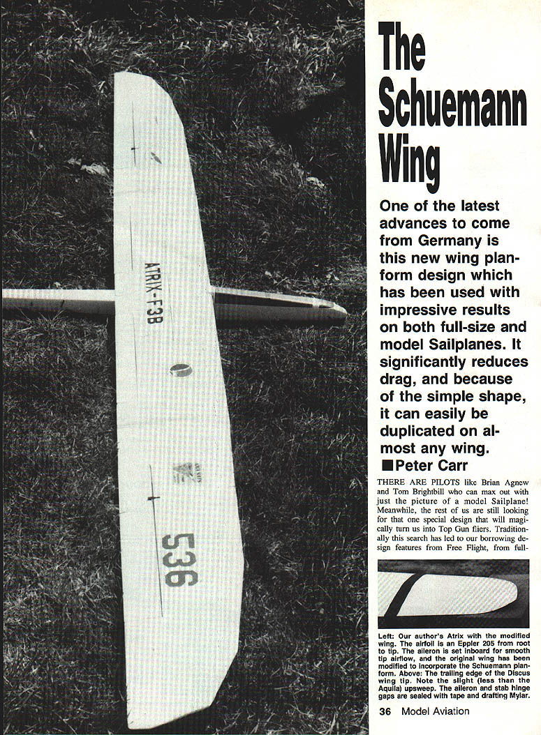
The modified Atrix model shown in the original photos is a rib-and-spar built-up structure; the wing could also be made from sheeted foam. No matter the internal material, the goal is a glass-smooth surface strong enough to withstand hard launches. Choose an airfoil that yields a good compromise between thermal performance and speed; several Eppler and Selig airfoils are top choices. Regardless of airfoil selection, the drag reduction inherent in the Schuemann planform will raise the wing's performance.
Nearly all high-speed powered aircraft use wings tapered from root to tip. Sailplanes generally use a constant chord partway to the tip to increase strength. The Schuemann wing, as used on the Discus and the modified Atrix, is constant chord to about half-span. Outboard from there, the leading edge is swept back in discrete steps—roughly 40%, then 20%, then 10%.
The modified Atrix wing diagram in the original article indicates the exact proportions used. At the tip, the latest Discus design employs a mild upturn of the trailing edge similar to the old Aquila model sailplane. The tip chord is small, however, and the upsweep probably has little effect. The center of pressure of the airfoil becomes "blurred" as it moves aft progressively toward the tip, which mitigates the noticeable aft-shift "step" some airfoils (like the Eppler 205) exhibit.
The result is a more forgiving airplane that is less touchy on elevator than the same 205 airfoil in a double-tapered wing. This is beneficial in windy weather or in light lift when you may be flying at the edge of the envelope. As with any swept-wing aircraft, the center-of-gravity (CG) needs to be further aft than on a straight wing. The modified Atrix is nearly unflappable with a CG at 25% of root chord, but becomes very civilized with the CG back at 33% to 35%.
Ballast and operational advantages
Using this planform also offers another advantage. For a sailplane with a straight wing, ballasting becomes necessary in windy conditions to improve penetration. As Herk Stokely wrote in his Soaring column, "you really need to increase your airspeed by about half the wind speed to get decent penetration." The problem with ballast is that it remains with the airplane during the entire flight.
A model with the clean, low-drag Schuemann wing will have a higher average unballasted speed while still working light lift and landing slowly. With this planform, you can fly unballasted when others are loading up, or add weight and search farther downwind in strong winds and still make it back to the landing circle.
As with the full-size Discus, you will have no trouble picking out your sailplane in a gaggle. It will likely be the highest one—flying faster than the others and working lift that no one else can reach.
References
- Spackman and Elliot, "The Schuemann Wing Planform," R/C Soaring Digest, July 1988.
- Herk Stokely, Flying Models magazine, September 1988.
- ATRIX plans, Model Aviation magazine, December 1986 issue.
Transcribed from original scans by AI. Minor OCR errors may remain.

