
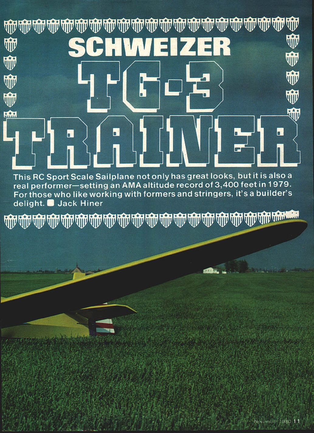
Schweizer TG-3 Trainer
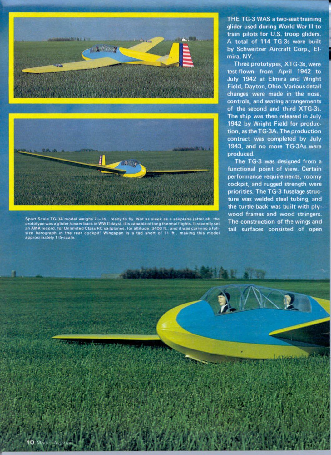
The TG-3 was a two-seat training glider used during World War II to train pilots for U.S. troop gliders. A total of 114 TG-3As were built by Schweizer Aircraft Corporation, Elmira, NY.
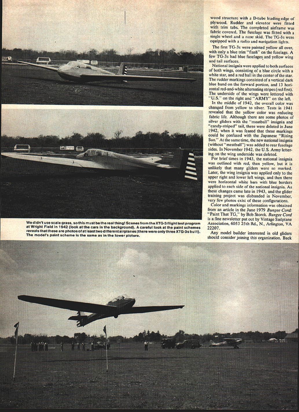
Three prototypes, XTG-3s, were test-flown from April 1942 to July 1942 at Elmira and Wright Field, Dayton, Ohio. Various detail changes were made to the nose, controls, and seating arrangements of the second and third XTG-3s. The design was released in July 1942 by Wright Field for production as the TG-3A. The production contract was completed by July 1943; no more TG-3As were produced.
Design and construction (full-size)
The TG-3 was designed with functionality and rugged strength as priorities, along with roomy cockpit accommodations. Key features:
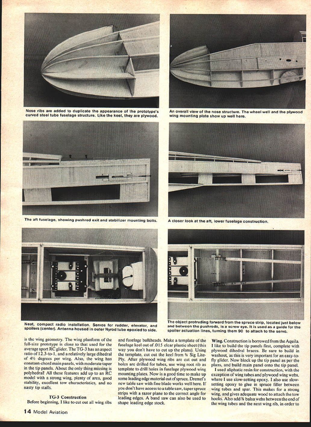
- Fuselage: welded steel tubing structure with a plywood-framed, wood-stringered turtledeck.
- Wings and tail: open wood structure with a D-tube plywood leading edge; rudder and elevator fitted with trim tabs.
- Covering: fabric-covered airframe.
- Undercarriage: single wheel and nose skid.
- Equipment: many TG-3s were fitted with radio and navigation lights.
The aircraft had a slab-sided, stringered fuselage and a squared-off empennage with no wing fillets or struts. The canopy was formed from flat sections.
Color and markings
Paint and markings evolved during 1942–1943:
- Early scheme: overall yellow with a blue trim "flash" on the fuselage; a few had blue fuselages with yellow wing and tail surfaces.
- Wing insignia: national insignia applied to both surfaces of both wings — blue circle with white star and red ball ("meatball") in the center. Rudder had a vertical dark blue band on the forward portion and 13 horizontal red-and-white alternating stripes (red first). Early in 1942 the wing undersides were lettered "U.S." on the right and "ARMY" on the left.
- Mid-1942 change: overall color changed from yellow to silver after tests showed yellow reduced fabric life. The candy-striped tail was deleted in June 1942 to avoid confusion with the Japanese Rising Sun; the new national insignia without the central red ball was applied to rear fuselage sides. In November 1942 the "U.S. / ARMY" wing-underside lettering was deleted.
- 1943 variations: for brief periods some insignia were outlined in red or yellow; later, insignia placement changed to upper right and lower left wings with horizontal white bars and blue borders applied beside the national insignia. These late changes are uncommon in surviving photos because glider training was disbanded in November 1943.
Color and markings information was obtained from the June 1979 Bungee Cord article "Paint That TG" by Bob Storck (Vintage Sailplane Association).
Postwar and preservation
At the end of the war, surviving TG-3s were sold as surplus. Postwar, a TG-3 held a U.S. duration record for an extended period. A number of TG-3s were still flying as of the 1970s; restoration efforts and information gathering (for example by the Air Force Museum and members of the Vintage Sailplane Association) aimed to preserve at least one TG-3 for display.
RC Sport Scale — advantages and notes
The TG-3 scales well as a Stand-Off (Sport) Scale RC sailplane. Advantages for modeling:
- Slab-sided, stringered fuselage and squared-off tail are straightforward to duplicate.
- No wing fillets or external struts to model.
- Canopy can be approximated with flat sheets.
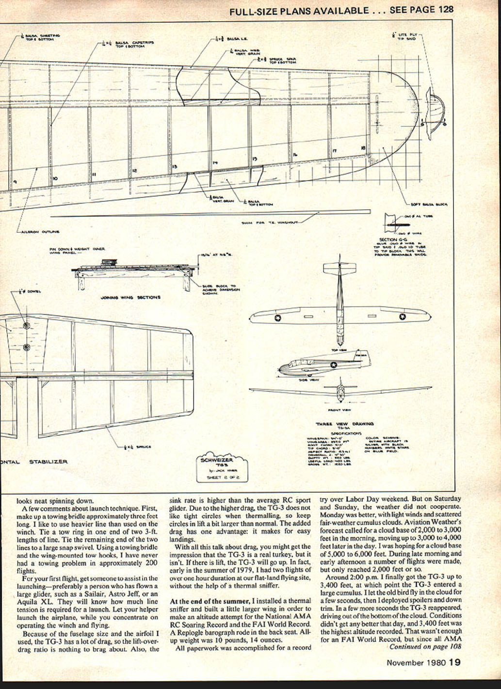
- Wing geometry is favorable: aspect ratio about 12.3:1, relatively large dihedral (~4–4½° per wing), constant-chord main panels with moderate taper in the tip panels — resulting in a strong wing, good stability, excellent tow characteristics, and benign tip-stall behavior.
- Polyhedral is missing on the full-sized wing; adding slight polyhedral to the model can improve turning without ailerons.
Modeling and flight practice remarks (Jack Hiner):
- A small amount of poly-dihedral at the taper break helps the model turn properly; it can be omitted if functioning ailerons are fitted.
- Coupling rudder and ailerons works well: suggest about 30° of rudder throw with small aileron deflection. Another option is coupled spoilers and rudder for coordinated turns.
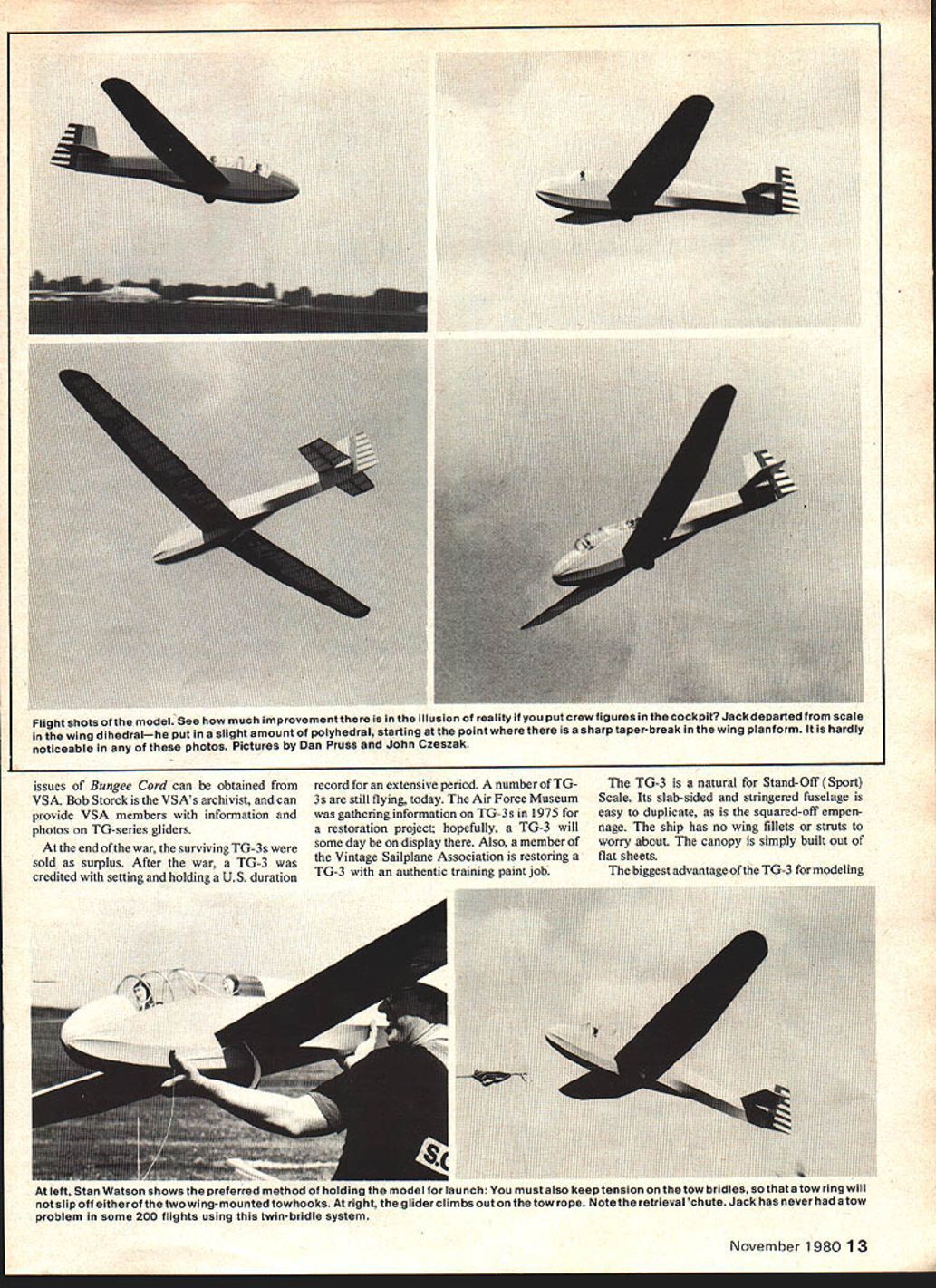
- Place small crew figures in the cockpit to enhance the illusion of scale in photos.
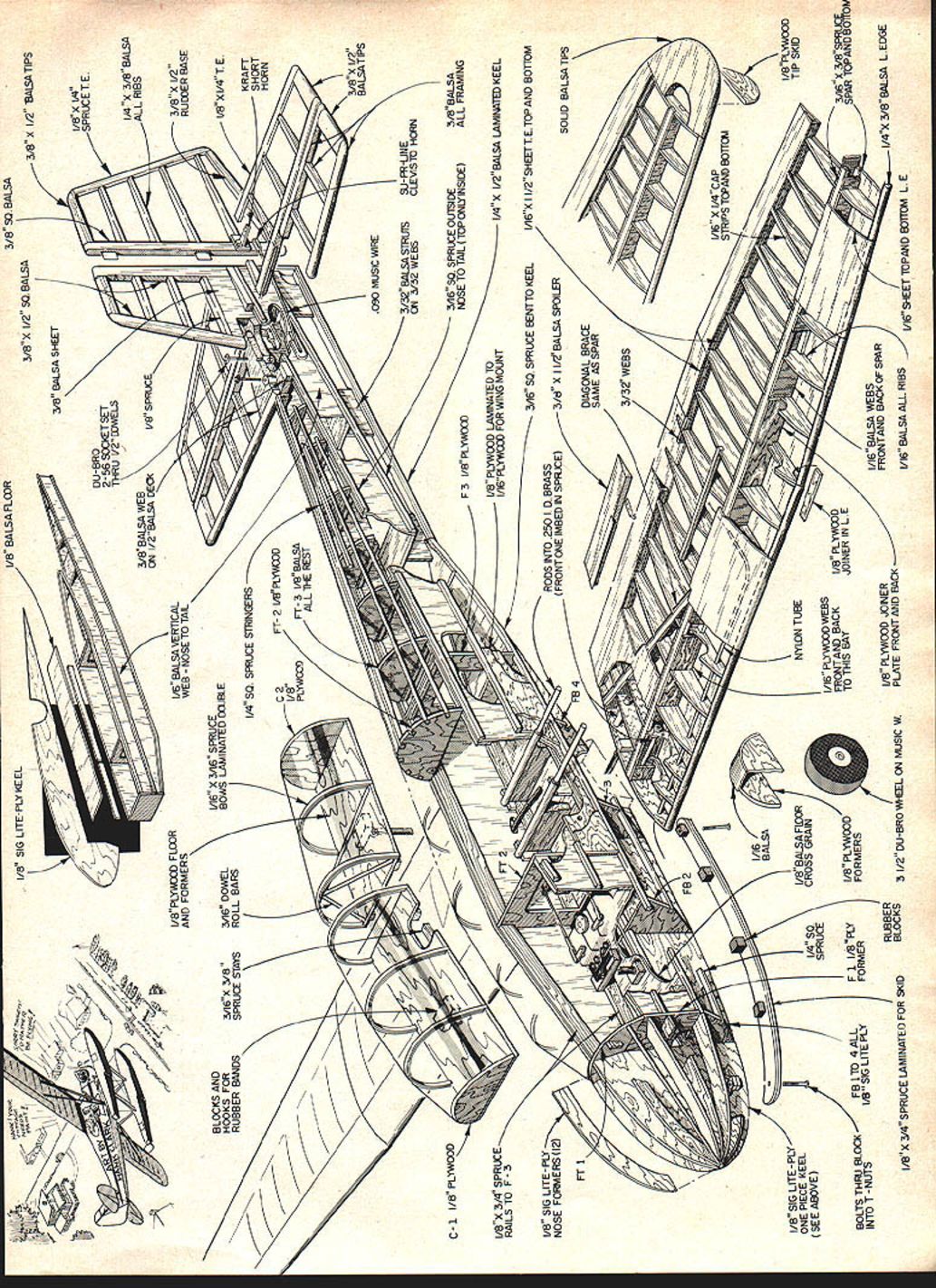
TG-3 Construction (model) — overview
Before beginning, cut all wing ribs and fuselage bulkheads. Make a keel template from 0.015" clear plastic and use it to cut the keel from 3/32" Sig Lite-Ply. Drill holes in plywood wing ribs for tubes, and use the wing root rib as a template to drill holes in fuselage plywood wing mounting plates.
Leading-edge stock: make from spruce. A fine-blade table saw is useful; if unavailable, taper spruce strips with a razor plane or use a band saw.
Adhesives: aliphatic resin (wood glue) is used for general construction; use slow-setting epoxy for wing tubes, plywood wing webs, and spruce filler between wing tubes and spar to create a strong bond and good attachment area for tow hooks.
Wing build sequence:
- Build tip panels first, including plywood dihedral braces; build in washout — critical for easy flying.
- Block up tip panels per plans; build main panels onto tips.
- Add 1/8" balsa webs between ends of wing tubes and the next rib to provide a glue surface and prevent tube rolling.
- Glue in spruce filler between wing tubes and spars with slow-setting epoxy.
- Use the wing plan technique (rub baby oil on the plan so paper becomes transparent) and build symmetrical halves.
Tail surfaces
Tail construction is straightforward. Make the horizontal stabilizer removable from the fuselage for transport. Cut taper in rudder and elevator ribs slightly oversize with a razor saw and dress with a sanding block. Use sheet metal screws to attach control horns to plywood mounts.
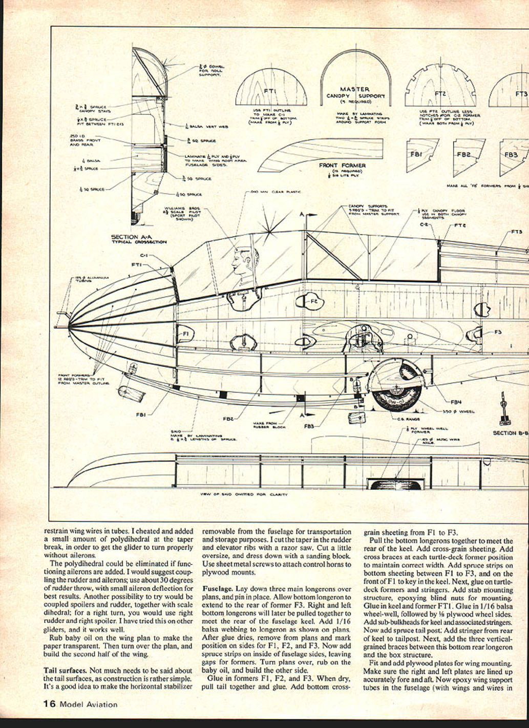
Fuselage (model) — step sequence
- Lay down three main longerons over plans and pin in place; allow bottom longeron to extend to the rear of former F3.
- Add 1/16" balsa webbing to longerons as shown on the plans. After glue dries, remove from plans and mark positions for formers F1, F2, F3.
- Add spruce strips inside fuselage sides, leaving gaps for formers; turn over plans (rubbed with baby oil) and build the opposite side.
- Glue in formers F1, F2, F3. When dry, pull tail together and glue.
- Add bottom cross-grain sheeting from F1 to F3 and across the keel area. Pull bottom longerons together to meet the rear of the keel and add cross braces at each turtle-deck former position to maintain width.
- Add spruce strips on bottom sheeting between F1 and F3 and on the front of F1 to key in the keel.
- Glue on turtle-deck formers and stringers. Add stab mounting structure and epoxy blind nuts for mounting.
- Glue in keel and former FT1. Glue in 1/16" balsa wheel-well followed by 3/16" plywood wheel sides. Add sub-bulkheads for the keel and associated stringers.
- Add the spruce tail post and stringer from the rear of the keel to the tailpost. Add three vertical grain braces between the bottom rear longeron and the box structure.
- Fit and add plywood plates for wing mounting; ensure right and left plates are accurately aligned fore and aft. Epoxy wing support tubes in the fuselage with wings and rigging in position.
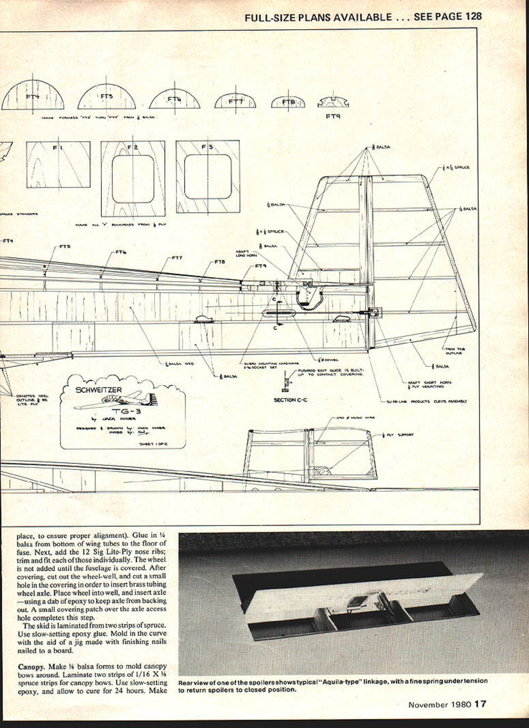
- Glue in 1/4" balsa from the bottom of wing tubes to the floor of the fuse. Add the 12 Sig Lite-Ply nose ribs; trim and fit individually.
Wheel installation: do not add the wheel until after covering. After covering, cut out the wheel-well and a small hole in the covering to insert a brass tubing wheel axle. Place wheel into well and insert axle, using a dab of epoxy to keep the axle from backing out. Patch the access hole with covering.
Skid: laminate the skid from two strips of spruce with slow-setting epoxy, molding the curve on a jig (finishing nails on a board help form the curve).
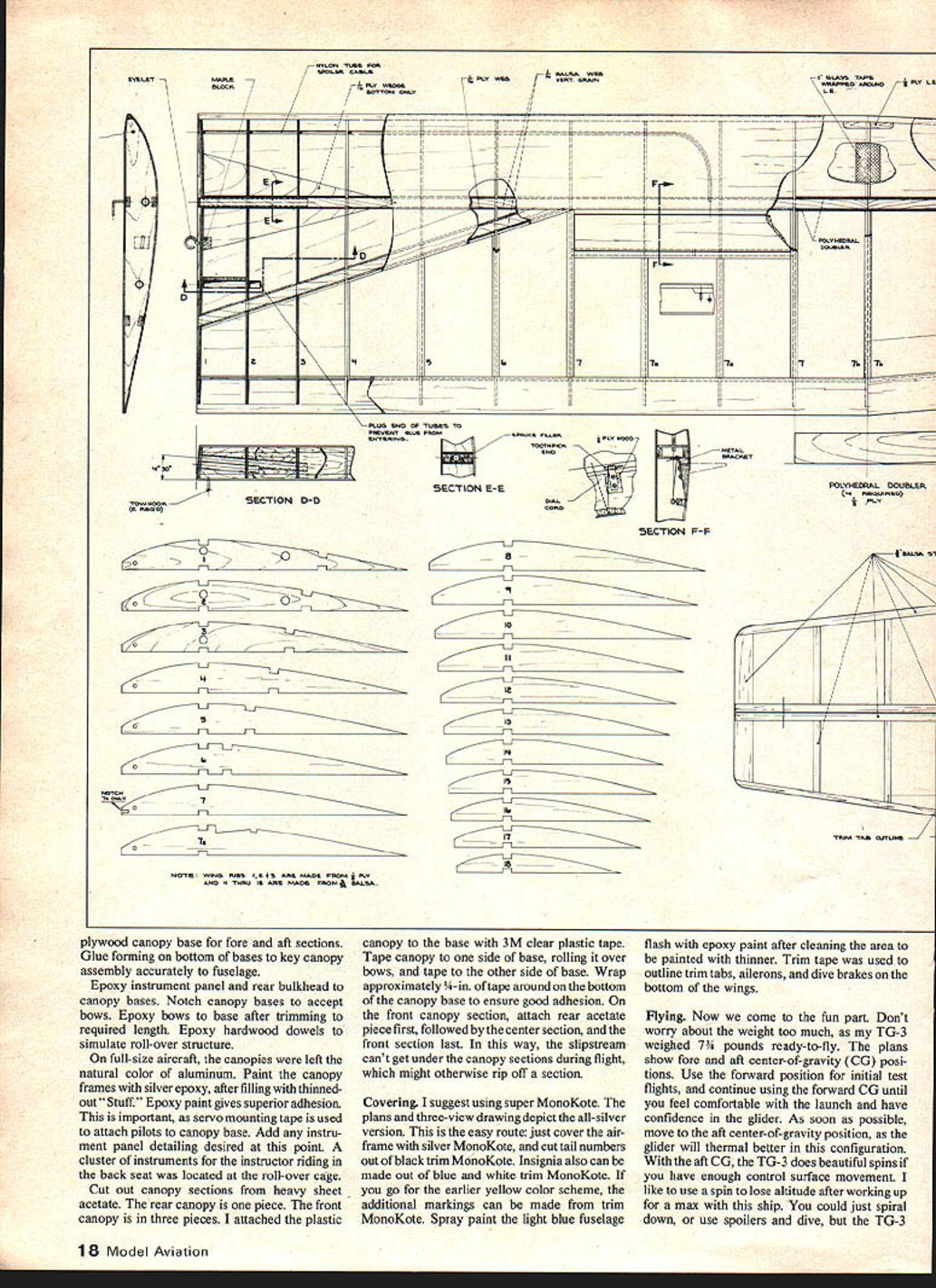
Canopy
- Make 1/8" balsa forms to mold canopy bows around. Laminate two strips of 1/16" x 3/8" spruce for canopy bows using slow-setting epoxy and cure for 24 hours.
- Make plywood canopy bases for fore and aft sections. Glue forming on the bottom of bases to key the canopy assembly to the fuselage.
- Epoxy instrument panel and rear bulkhead to canopy bases. Notch bases to accept bows; epoxy bows to bases after trimming to length. Epoxy hardwood dowels to simulate rollover structure.
- On the full-size aircraft canopies were natural aluminum; paint canopy frames with silver epoxy after filling with thinned "Stuff." Epoxy paint gives superior adhesion.
- Cut canopy sections from heavy sheet acetate: rear canopy is one piece, front canopy in three pieces. Attach plastic canopy to the base with 3M clear plastic tape: tape one side of the base, roll over the bows and tape the other side, wrapping approximately 1/4" of tape around the bottom to ensure adhesion. Attach the near acetate piece first, then the center, then the front to reduce risk of wind lifting sections in flight.
Covering
Super MonoKote is recommended. The plans and three-view depict the all-silver version, which is the simplest finish: cover the airframe with silver MonoKote, cut tail numbers from black trim MonoKote, and make insignia from blue and white trim MonoKote. For the earlier yellow scheme, use appropriate trim MonoKote markings. Spray the light-blue fuselage flash with epoxy paint after cleaning with thinner. Trim tape can be used to outline trim tabs, ailerons, and dive brakes on the bottom of the wings.
Flying and handling (model)
- Weight: the author's TG-3 model weighed 7-1/4 lb ready-to-fly; a later altitude-attempt configuration weighed 10 lb 14 oz with barograph equipment.
- Center of gravity: plans show forward and aft CG positions. Use the forward CG for initial test flights. Move to the aft CG after you are comfortable — the glider thermals better aft but can spin readily with sufficient control throw.
- Trim: a slight nose-up trim can be used after winding up for a max; spoilers or a spiral-down are alternatives.
- Thermalling: the TG-3 has higher drag and a higher sink rate than the average sport RC glider; avoid tight circles and use slightly larger turns in lift. In strong lift the TG-3 will bank a few degrees and can be made to hook cleanly with opposite-rudder input.
- Tow handling: excellent when properly rigged. Use twin bridles to wing-mounted tow hooks rather than a single nose hook to prevent the tow ring from slipping off. A retrieval chute can be fitted in the tail.
Towing bridle recommendation (author's practice):
- Make a towing bridle approximately 3 ft long using heavier line than used on the winch.
- Tie a tow ring in one end of two 3-ft lengths of line. Tie the remaining ends of the two lines to a large snap swivel.
- Use the wing-mounted tow hooks with this twin-bridle system. The author reported about 200 flights without a towing problem using this rig.
Launch technique: have an experienced helper to assist in launching and to manage tension; let the helper launch while you concentrate on the winch and flying.
Altitude attempt and record (model)
- In 1979 the author's RC TG-3 set an AMA altitude record of 3,400 ft. A Replogle barograph was carried in the back seat for documentation.
- Flights were made over a Labor Day weekend; on the successful day light winds and scattered cumulus allowed a climb to 3,400 ft. The TG-3 entered a cumulus briefly, then descended under spoilers and reappeared from the cloud core.
- The recorded altitude was sufficient for an AMA National Soaring Record because national records were at zero at that time, though it was short of an FAI world record.
Practical tips and modifications
- If using no ailerons, a small amount of poly-dihedral at the taper break improves turning. Adding functioning ailerons eliminates the need for poly-dihedral.
- Try coupling rudder and ailerons (about 30° rudder throw with small aileron deflection) or try coupled spoilers and rudder for scale dihedral turns (right rudder + right spoiler for a right turn).
- For transport and storage, make the horizontal stabilizer removable.
- Place a retrieval chute in the tail if desired.
References
- Ernest Schweizer, "The TG-3A," Soaring, May–June 1944.
- AIR TRAILS, Spring 1979, "Glider Factory," Technical Order No. 09-30AB-2, Erection and Maintenance Instructions, TG-3A Glider.
- Schweizer Aircraft Corporation drawings.
- National Archives photos (documentary photography, 1361 ST Photo Sqdn., 1221 South Fern St., Arlington, VA 22202). Official USAF photos for sale; write for price list and ordering instructions.
- 21298AC — Front View XTG-3.
- 21294AC — Tow Plane, XTG-3 in Background.
- 21257AC — Side View XTG-3.
- 21296AC — XTG-3 at Takeoff.
- Bungee Cord, June 1979, "Paint That TG," by Bob Storck (Vintage Sailplane Association, 6053 25th Rd. N., Arlington, VA 22207).
Color codes (reference)
- Color (Aircraft)
- Yellow — FS 15123 — Dupont 224
- Blue — FS 15123 — Dupont 98013
- Color (Insignia)
- White — FS 17875 — Dupont: not critical
- Red — FS 11316 — Dupont 1865 (48)
- Blue — FS 15044 — Dupont 2063
- Black — FS 17038 — Dupont: not critical
Contact / closing
The TG-3 is an easy-to-build and enjoyable Stand-Off (Sport) Scale sailplane. If you are interested in old gliders or model-building resources, consider joining the Vintage Sailplane Association; their archivist Bob Storck can provide information and photos. For construction help, the author (Jack Hiner) offered assistance at 2213 Prentice Creek, Apt. 104, Downers Grove, IL 60515.
Transcribed from original scans by AI. Minor OCR errors may remain.

