
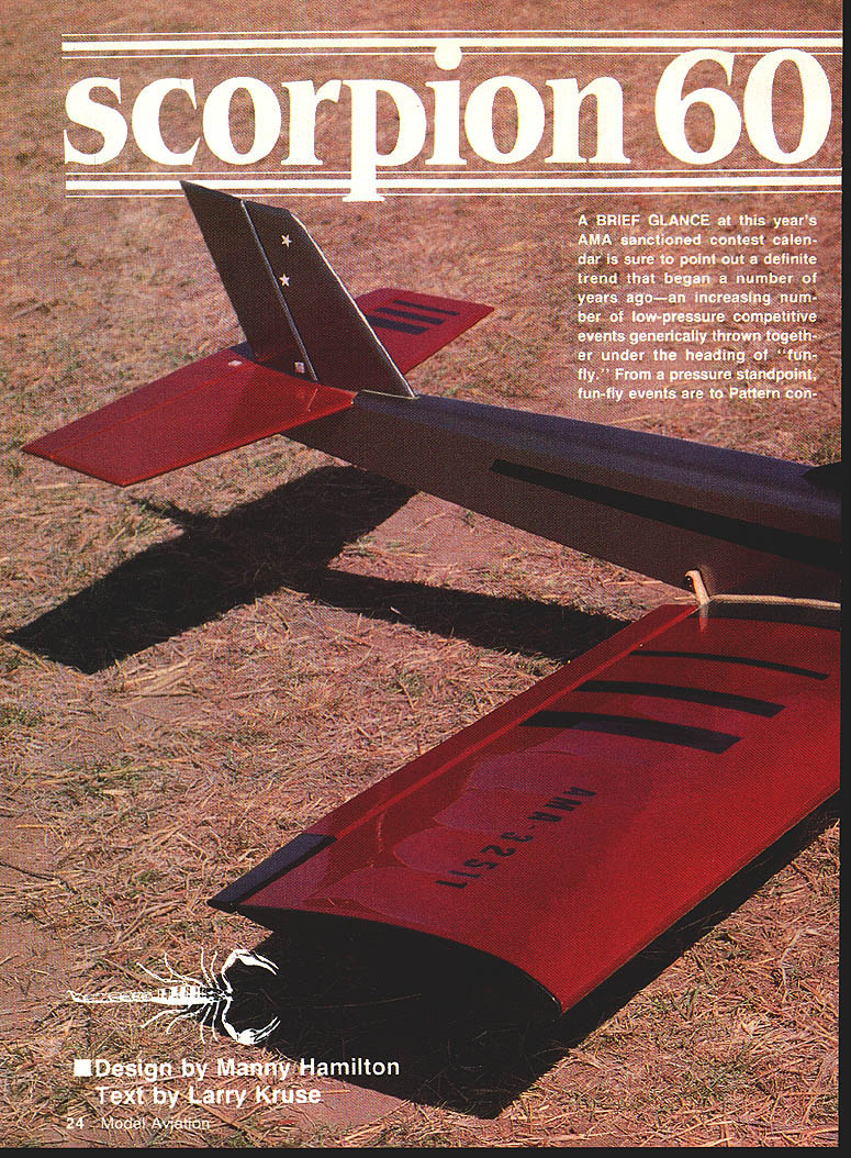
Scorpion 60
Design by Manny Hamilton Text by Larry Kruse
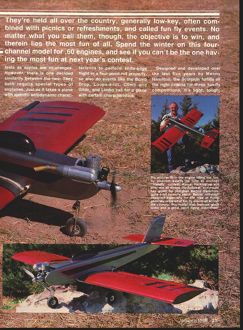
A brief glance at this year's AMA-sanctioned contest calendar shows a clear trend that began several years ago: an increasing number of low-pressure competitive events grouped under the heading "fun-fly." These events are generally low-key, often combined with picnics or refreshments, and called fun-fly contests. From a pressure standpoint, fun-fly events are to Pattern contests as apples are to oranges, but both require specialized airplanes. Events like Bomb Drop, Loops-a-lot, Climb and Glide, and Limbo call for aircraft with certain characteristics.
Designed and developed over five years by Manny Hamilton, the Scorpion meets the criteria for fun-fly competitions. It's light, tough, fully aerobatic, and—thanks to its semi-symmetrical airfoil and generous dihedral—stable enough for novice fliers. The Scorpion is ideal for a four-channel model powered by a .60 engine and has enjoyed regional popularity across Kansas, Colorado, Oklahoma, Texas, and New Mexico.
Construction
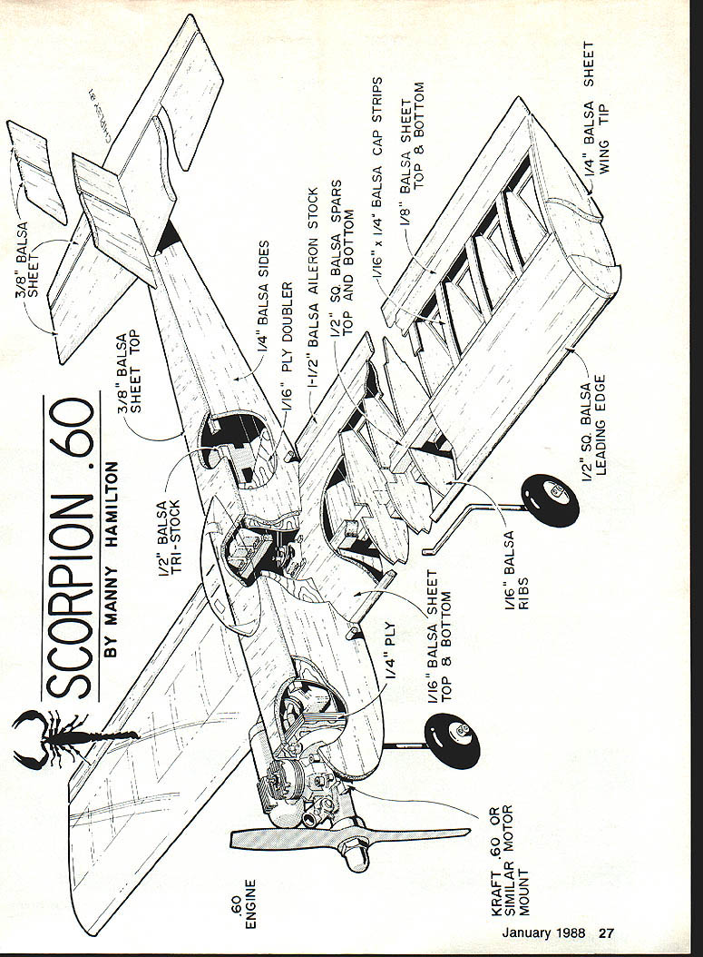
Two surprising features of the Scorpion are the absence of internal fuselage formers and the extensive use of full-depth plywood doublers. Other than the plywood firewall, there are no interior fuselage members. This formerless approach makes installing radio gear and hooking up control rods easy, and—contrary to what you might assume—produces a very strong, damage-resistant fuselage. Strength comes from full-depth ply doublers from the wing area forward and from the fuselage-length triangular stock that provides increased gluing surface between pieces.
Wing
Because the wing is used to help align the stabilizer and rudder during fuselage construction, build it first. Pre-kit the wing components to save time.
- Stack-saw the ribs and cut out the pine landing-gear block. The slot for the landing-gear wire can be dadoed on a table saw or carefully carved by hand with an X-Acto narrow concave blade.
- Prepare the necessary spar and leading-edge stock (1/2 in. square spars are used in the plans) and 1/16-in. balsa sheeting and cap strips for the trailing edge.
- Form the right wing panel first: glue a 1/2-in.-sq. piece of spar stock to the right front side of the pine landing-gear block. Mark the exact center of the landing-gear block, place the slotted side down, and pin the spar alongside with the assembly flat on the building board.
- Pin down the bottom trailing-edge piece, shim up the spar/landing-gear block along its length, and fit and glue the tip rib and center rib over the spar and trailing edge. Install the remaining ribs in sequence.
- Add the top spar and top trailing-edge piece, then glue the 1/2-in.-sq. leading edge. Both leading-edge pieces (and spars) require a slight bevel at the ends to butt against each other at the center section.
- Remove the right panel from the building board and construct the left panel in the same fashion. Block up the right panel while assembling the left.
- Strive for good, close-fit butt joints where the wing halves join; use epoxy for these joints.
- Plank the entire leading edge with 1/16-in. sheeting. Wet the top sheeting so it conforms to the rib curvature. Install landing-gear support blocks, plank the center section, and cut the aileron servo hole.
- Complete the wing with 3/16-in. rib cap strips and 1/8-in. sheet tip plates. Sand to shape and round the leading edge per the plans.
- Drill 5/32-in. (or as required) holes in the gear support blocks and in the slotted side of the landing-gear block, maintaining alignment.
- Fit the servo into the cutout and mount it on short strips of 1/16-in. plywood glued to the sheeting. Bevel the front of the aileron stock for hinge clearance, cut the ailerons to thickness, chamfer the leading edge to a "V" shape, drill for torque rods, and epoxy the rods in place.
- Final sand both wing and ailerons and prepare for covering before installing hinges.
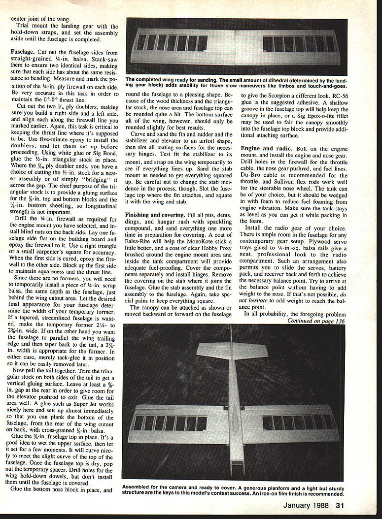
Optional: if you are uneasy about the center-section strength, wrap a 2-in.-wide strip of fiberglass cloth around the center section and the bottom of the fuselage. This adds little weight and increases confidence for the cautious builder.
Fuselage
- Cut fuselage sides from straight-grained 1/4-in. balsa; stack-saw to ensure two identical sides with similar bending resistance.
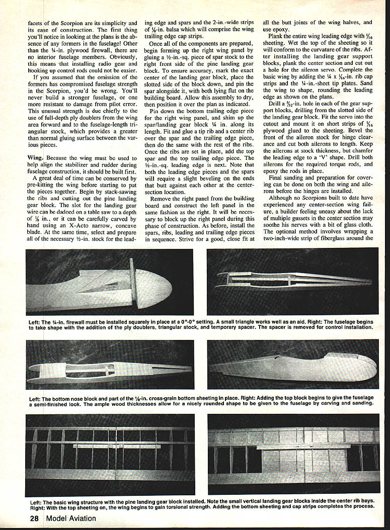
- Accurately measure and mark the firewall position on each side (plans show a 1/4-in. plywood firewall). Cut two 1/4-in. ply doublers (left and right) and align them along the firewall line. Use five-minute epoxy to install the doublers and let them set.
- Glue 1/2-in. triangular stock in place along the fuselage sides to provide increased gluing surface for the 3/8-in. top and bottom blocks and the 1/8-in. bottom sheeting. Longitudinal strength of the triangular stock is less important than its gluing area.
- Drill the firewall as required for your engine mount and install blind nuts on the back side. Epoxy the firewall to one fuselage side (use a square for accuracy), let cure, then epoxy to the other side and block up to maintain squareness and thrust line.
- Because there are no formers, temporarily install a scrap 1/4-in. balsa former behind the wing cutout to establish fuselage shape. The width of this temporary former determines the final fuselage profile:
- 2-1/2 to 2-3/4 in. wide for a tapered, streamlined fuselage.
- about 2-1/2 in. wide to parallel the wing trailing edge before tapering to the tail.
Tack-glue the temporary former so it can be easily removed later.
- Trim the triangular stock at the tail to create vertical gluing surfaces. Leave at least a 5/8-in. gap at the rear for the elevator pushrod exit. Glue the tail area thoroughly (fast-setting glues like Super Jet work well) and plank the bottom of the fuselage aft of the wing cutout with cross-grained 1/4-in. balsa.
- Glue the 3/8-in. fuselage top in place—wetting the top surface briefly helps it curve to meet the fuselage contours. Once dry, remove the temporary spacer.
- Drill holes for wing hold-down dowels but install them after covering.
- Glue the bottom nose block and shape the fuselage. Round the nose area and fuselage top as desired; keep the bottom surface aft of the wing only slightly rounded for best results.
- Carve and sand fin, rudder, stabilizer, and elevator to an airfoil shape. Slot mating surfaces for hinges and test-fit the stabilizer and fin. Temporarily strap the wing on to check alignment, and adjust stub or mount sanding as needed—avoid changing stabilizer incidence.
Notes on controls and gear:
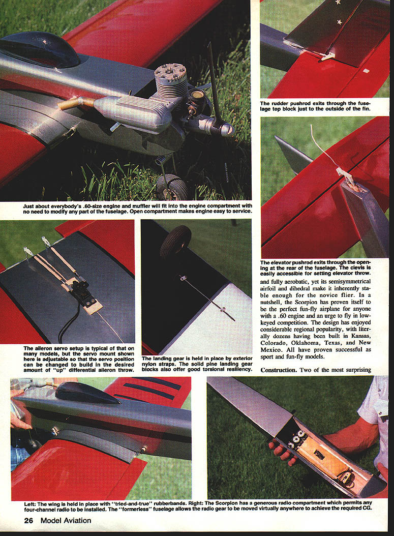
- The elevator pushrod exits through an opening in the rear fuselage with the clevis easily accessible.
- The rudder pushrod exits through the fuselage top just outside the fin.
- The landing gear is held in place with exterior nylon straps; solid pine landing-gear blocks provide good torsional resiliency. Rubber bands may be used as an alternative hold-down method.
- The formerless fuselage provides a generous radio compartment; the fuel tank and landing gear can be moved to achieve proper balance.
Finishing and covering
- Fill pits, dents, and dings with spackling compound and sand smooth.
- Apply a coat of Balsa-Rite to help MonoKote adhere.
- Brush a coat of clear Hobby Poxy around the engine mount area and inside the tank compartment for fuel-proofing.
- Cover components separately and install hinges. Remove covering on the stabilizer where it joins the fuselage before final installation.
- Glue the stab and fin assemblies to the fuselage, taking care to keep everything square.
- Attach the canopy as shown on the plans or adjust its fore/aft position for a different appearance. RC-56 is a suggested adhesive. A shallow groove in the fuselage top or a Sig Epox-o-lite filler can help fair and secure the canopy.
Engine and radio
- Bolt on the engine mount and install the engine and nose gear. Drill the firewall for throttle cable, nose-gear pushrod, and fuel-line routing.
- Recommended control hardware: Du-Bro cable for throttle, Sullivan flex rods for the steerable nose wheel.
- Use a foam wedge to restrain the fuel tank and reduce fuel foaming from engine vibration. Keep the tank as level as possible while packing foam around it.
- Install radio gear in the roomy fuselage compartment. Plywood servo trays glued to 1/4-in.-sq. balsa rails produce a neat look and allow sliding servos, battery pack, and receiver fore and aft to achieve C.G. without adding ballast—try to balance without nose weight, but add weight if necessary.
Specifications and performance
- Power: .60-size engine recommended (KRAFT .60 or similar).
- Suggested aileron range: 3/4 in. up, 1/2 in. down.
Competition record (recent fun-fly contests):
- 18 first-place awards
- 16 second-place awards
- 12 third-place awards
The Scorpion was flown exclusively by the 1985 high-point winner of the High Plains Radio Control Association (Kansas, Oklahoma, Texas, New Mexico, and Colorado), demonstrating its effectiveness in fun-fly competition.
With some practice and setup, the Scorpion is a capable choice for sport fliers and fun-fly competitors alike—light, strong, and forgiving enough for novices while fully aerobatic for experienced pilots.
Transcribed from original scans by AI. Minor OCR errors may remain.

