
Screamin' Eaglet
By John Hunton
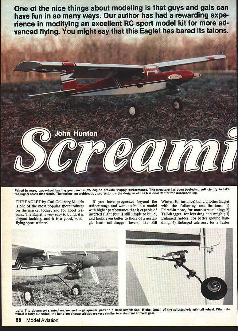
One of the nice things about modeling is that guys and gals can have fun in so many ways. I had a rewarding experience modifying an excellent RC sport model kit for more advanced flying. You might say this Eaglet has bared its talons.
THE EAGLET by Carl Goldberg Models is one of the most popular sport trainers on the market today—and for good reasons. The Eaglet is very easy to build, elegant looking, and a good, solid-flying sport trainer.
If you have progressed beyond the trainer stage and want higher performance capable of inverted flight (but still simple to build and appealing to tail-dragger fans), build another Eaglet with the following modifications:
- Faired-in nose for more streamlining
- Tail-dragger configuration for less drag and weight
- Enlarged rudder for better ground handling
- Enlarged ailerons for a faster roll rate
- Modified airfoil for improved inverted flight
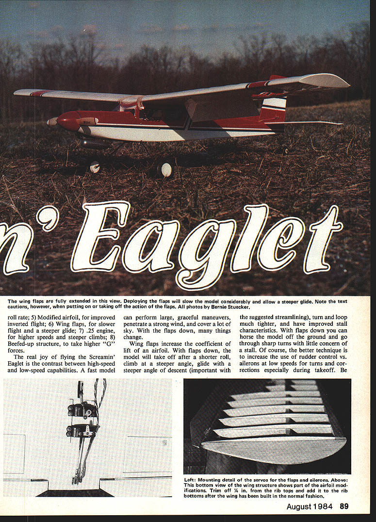
- Wing flaps for slower flight and steeper glide
- .25 engine for higher speeds and steeper climbs
- Beefed-up structure to withstand higher G forces
The result is real joy flying. The Screamin' Eaglet provides a dramatic contrast between high-speed and low-speed capabilities. At high speed it performs large, graceful maneuvers and can penetrate strong wind. With flaps down, its behavior changes: shorter takeoff roll, steeper climb, steeper glide, slower airspeed and improved low-speed handling.
Flight Characteristics
- Wing flaps increase the lift coefficient. With flaps down the model will take off after a shorter roll, climb more steeply, and glide at a steeper descent angle.
- Proper streamlining tightens loops and improves stall characteristics.
- With full flaps deployed, the effective angle of attack of the wing increases and trim is greatly affected. When you pop the flaps down, be ready to apply down-elevator when flying very slowly. Conversely, when you retract the flaps, have plenty of altitude and speed because the nose will tend to drop.
- For low-speed turns and corrections—especially during takeoff—use rudder more than ailerons. With flaps down you can hustle the model off the ground and go through sharp turns with little concern about a stall, provided you use good rudder technique.
Tail-dragger Handling
I have flown the tail-dragger version of the Eaglet; it is an ideal model for learning Carl Goldberg’s basic design. The long, slim fuselage provides plenty of yaw inertia (rudder control). Most fears of tail-draggers come from short-coupled models; this isn’t one.
- An adjustable-length tailwheel is shown on the plan. If you haven’t flown a tail-dragger, start with the tailwheel fully extended. With a long tailwheel and flaps up the model must attain an airspeed well over stall to become airborne.
- Rudder-control takeoff is similar to nose-gear models because full power provides good airflow over the rudder.
- Landings are different: with the engine idling the airflow over the rudder is poor on final approach. Use rudder to steer and aileron to cancel crosswind—you must land with the wing low. Once the model contacts the ground, maintain rudder control with the tailwheel extended. The tailwheel will contact first; pitch the model slightly down to kill lift and provide good wheel contact for steering.
- As skills increase, shorten the tailwheel for quicker takeoffs. If the model tends to porpoise on landing, lengthen the tailwheel slightly. Using flaps during landing helps by slowing the plane and improving stall characteristics.
Construction
Follow the kit instructions except for the changes below.
Wing
- Modify the top profile of all wing ribs and cut a new spar slot per the templates. Build the wing with a flat bottom except for the leading edge.
- The leading edge can be hung over the edge of the bench and pinned to the ribs. Trim off rib tops and add rib bottoms after the wing is assembled in the normal fashion.
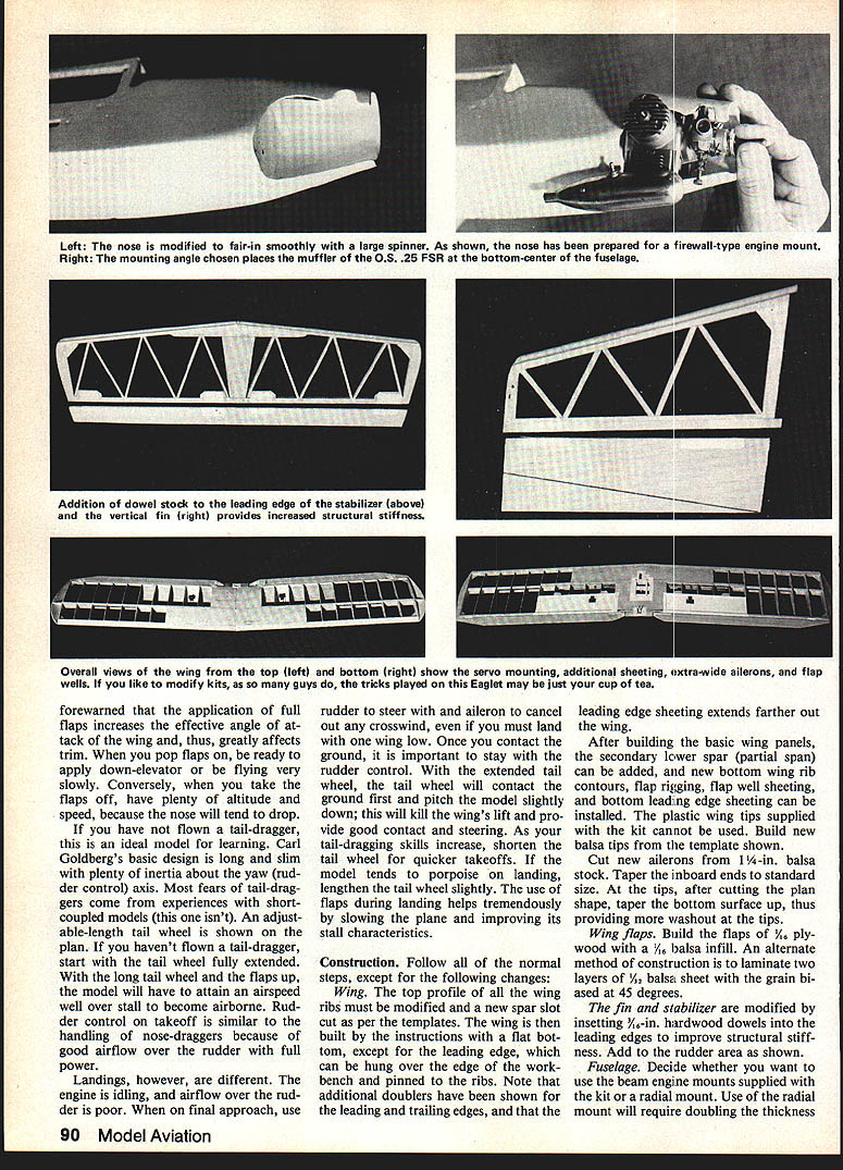
- Note the additional doublers on the leading and trailing edges; the leading edge sheeting extends farther out on the wing.
- After building the basic wing panels, add the secondary lower spar (partial span), new bottom wing rib contours, flap rigging, flap well sheeting, and bottom leading edge sheeting.
- The plastic wing tips supplied with the kit cannot be used—build new balsa tips from the template shown.
- Cut new ailerons from 1/4-in. balsa stock. Taper the inboard ends to standard size. At the tips, taper the bottom surface up to provide more washout at the tips.
- Install extra-wide ailerons and flap wells as detailed in the plans. Mount servos and install flap and aileron linkages as shown.
Wing flaps
- Build the flaps from 1/4-in. plywood with a 1/8-in. balsa infill. An alternative is laminating two layers of 1/8-in. balsa with the grain biased at 45 degrees.
- Remember: flaps increase the effective angle of attack and greatly affect trim. Pop flaps down and be ready to apply down-elevator when flying very slowly. When retracting flaps, ensure you have plenty of airspeed and altitude because the nose will tend to drop.
Fin and Stabilizer
- Modify the fin and stabilizer by inserting 1/8-in. hardwood doublers into the leading edges to improve stiffness.
- Increase rudder area as shown on the plans.
Fuselage
- Decide whether to use the beam engine mounts supplied or a radial mount. A radial mount requires doubling the firewall thickness.
- Decide whether to use right and down thrust (to improve low-speed handling, particularly during takeoff) or to set the engine straight for maximum speed.
- If you use the semi-inverted engine installation shown on the modifications plan, locate the fuel tank low in the fuselage.
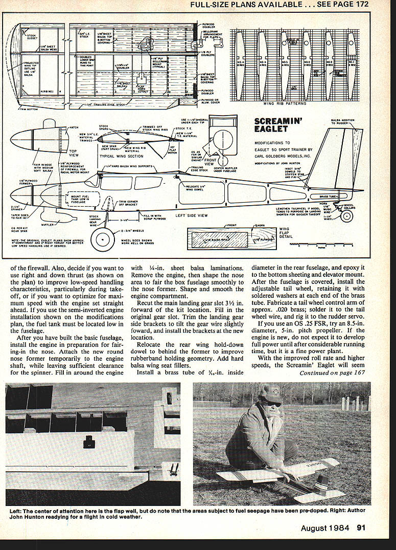
- After building the basic fuselage, install the engine in preparation for fairing-in the nose. Attach the new round nose former temporarily to the engine shaft, leaving sufficient spinner clearance. Fill around the engine with 1/4-in. sheet balsa laminations. Remove the engine, then shape the nose area to fair the box fuselage smoothly to the nose former. Shape and smooth the engine compartment.
- Recut the main landing gear slot 3-1/2 in. forward of the kit location and fill the original gear slot. Trim the landing gear side brackets to tilt the gear wire slightly forward and install the brackets at the new location.
- Relocate the rear wing hold-down dowel to behind the former to improve rubberband holding geometry. Add hard balsa wing seat fillers.
- Install a brass tube of 5/32-in. inside diameter in the rear fuselage and epoxy it to the bottom sheeting and elevator mount. After covering, install the adjustable tailwheel, retaining it with soldered washers at each end of the brass tube.
- Fabricate a tailwheel control arm of approx. .020-in. brass; solder it to the tailwheel wire and rig it to the rudder servo.
Spinner and Nose
- The nose is faired-in smoothly to provide a large spinner mounting area. The mounting angle places the muffler or OS .25 FSR toward the bottom-center of the fuselage.
Structure, Sheeting and Finishing
- Beef up structure where indicated so the model can take higher G forces. Reinforce the wing and fuselage joints and install the brass tube in the rear fuselage to retain the adjustable tailwheel.
- Epoxy bulkheads and sides where noted. Use 5-minute epoxy on ply-to-balsa joints.
- After covering, balance the model at the wing trailing edge. For rigging and final setup, refer to the trim and control movement notes in the plans.
Engine, Prop and Test Flights
- If you use an OS .25 FSR, try an 8-1/2 in. diameter, 5-in. pitch propeller. If the engine is new, do not expect full power until after considerable running time.
- The Screamin' Eaglet will feel much more sensitive and responsive compared to the stock kit Eaglet. Have an experienced pilot help check out and trim the model if possible.
Trimming and Flight Setup
- At the stabilizer trailing edge, you may need a bit more thickness for a good glide. Move the tail assembly so there's just a hint of left glide turn; then add some 1/64" sq. by 1/4"-long keys to position the stab on the platform. Make sure the keys are glued to the stab and that the stab is still free to pop up.
- Try low-power flights first. The model should climb gently to the right even at low throttle. If it won't, check for warp or rudder/engine offset and correct it. Work up slowly to more power.
- Most of my models fly best when using less than full power.
You will quickly become acclimated and appreciative of this higher-performance variation.
Transcribed from original scans by AI. Minor OCR errors may remain.

