

SE-5
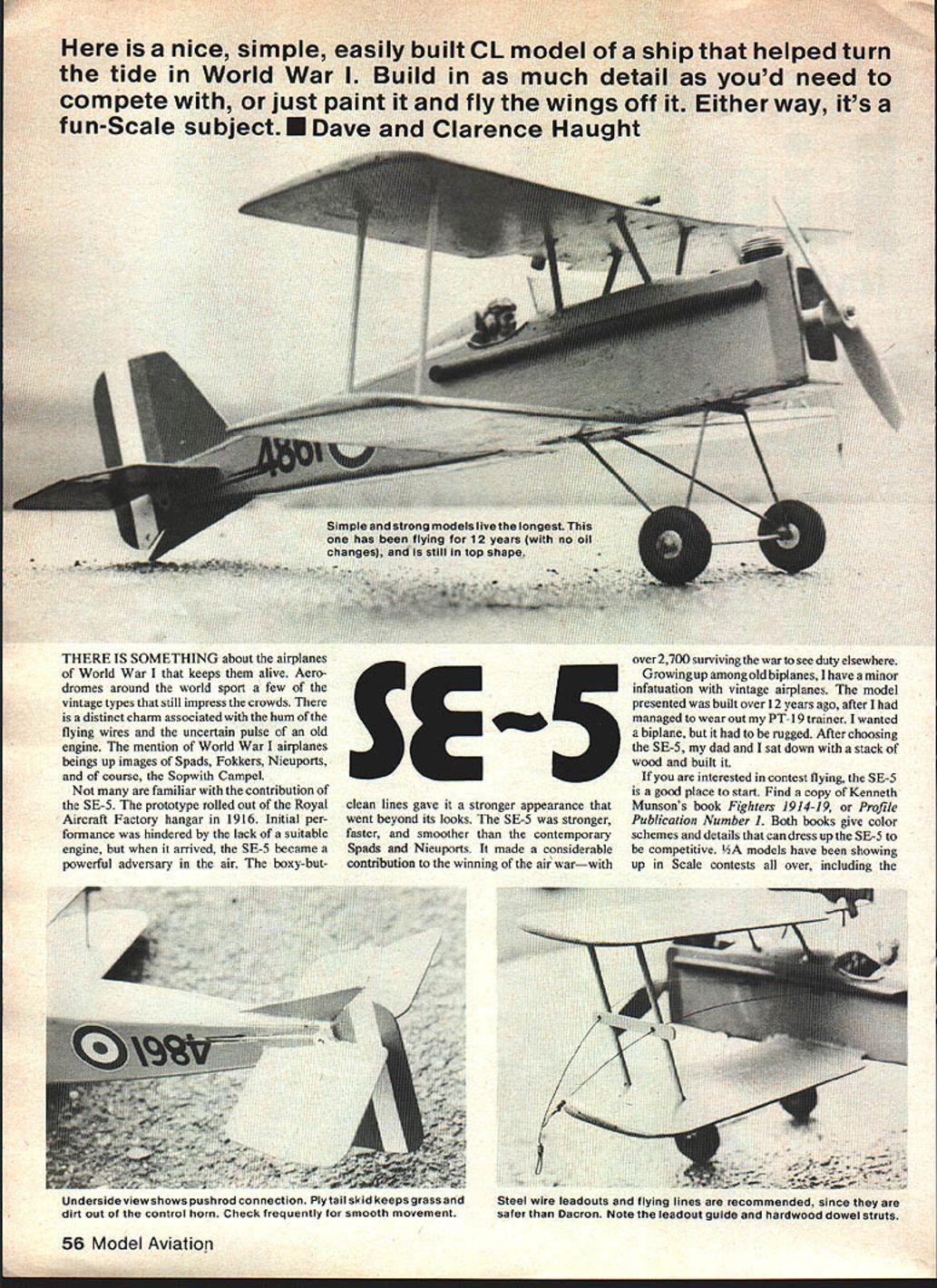
Here is a nice, simple, easily built CL (control-line) model of a ship that helped turn the tide in World War I. Build in as much detail as you'd need to compete with, or just paint it and fly the wings off it. Either way, it's a fun-scale subject. — Dave and Clarence Haught
Background
There is something about the airplanes of World War I that keeps them alive. Aerodromes around the world sport a few of the vintage types that still impress the crowds. There is a distinct charm associated with the hum of the flying wires and the uncertain pulse of an old engine. Mention of World War I airplanes brings up images of Spads, Fokkers, Nieuports, and of course, the Sopwith Camel.
Not many are familiar with the contribution of the SE-5. The prototype rolled out of the Royal Aircraft Factory hangar in 1916. Initial performance was hindered by the lack of a suitable engine, but when it arrived, the SE-5 became a powerful adversary in the air. The boxy-but-clean lines gave it a stronger appearance that went beyond its looks. The SE-5 was stronger, faster, and smoother than contemporary Spads and Nieuports. It made a considerable contribution to the winning of the air war — with over 2,700 surviving the war to see duty elsewhere.
Growing up among old biplanes, I have a minor infatuation with vintage airplanes. The model presented was built over 12 years ago, after I had managed to wear out my PT-19 trainer. I wanted a biplane, but it had to be rugged. After choosing the SE-5, my dad and I sat down with a stack of wood and built it.
If you are interested in contest flying, the SE-5 is a good place to start. Find a copy of Kenneth Munson's Fighters 1914–19, or Profile Publication Number 1. Both give color schemes and details that can dress up the SE-5 to be competitive. 1/4A models have been showing up in scale contests all over, including the Nationals. It's easy to see — an inexpensive build that takes up little space in the car. Construction was kept as simple as possible to speed up building time.
Materials and preparation
- Music wire or welding rod for landing gear.
- 1/8-in. hardwood dowel for struts; 1/8-in. soft balsa for crosspieces.
- Medium-soft sheet balsa for wing planks (Sigs 1/4-in. airfoiled planks are available).
- Fine copper wire for landing gear wrapping.
- Epoxy, slow-drying epoxy for dihedral joints, clear dope, paint.
- Steel wire leadouts (recommended), or Dacron if preferred.
- Aluminum tube and scrap balsa for machine gun; dowels for exhaust stacks.
- Clear plastic for windscreen.
- 35-ft steel flying lines (recommended for 1/2A/1/4A) and other usual modeling tools.
Fuselage construction
- Start cutting out fuselage parts.
- Drill holes for landing gear wrappings, engine mount holes, and bellcrank mounting bolts.
- Follow the assembly sketch and plan; take time to ensure formers are glued square.
- Bend up the landing gear from music wire or welding rod.
- Install bellcrank, leadouts and landing gear.
- Wrap the landing gear at the firewall with fine copper wire and epoxy well.
- The rear landing gear wire will be fitted into a notch in the bottom of the lower wing. Once fitted, plank the bottom of the fuselage.
- Note grain direction when planking — this adds strength. Fuselage planking will sag between formers; take care to maintain shape.
- Check the control system for smooth operation.
- Add top blocks, dry carve the blocks to shape, sand and cut out the cockpit opening. Carve and add the headrest.
- Drill a 5/16-in. diameter hole in the right rear corner of the engine compartment floor to serve as an oil drain hole.
Set the fuselage assembly aside while you build the tail and wings.
Stabilizer and rudder
- Cut out and sand stabilizer and rudder parts.
- Glue the offset rudder/fin shown on the plan.
- Hinge the stabilizer and elevator with cloth or plastic hinges. Make sure hinges move freely and smoothly before glue has set.
- Notch the fuselage to fit the stabilizer. Carefully align and glue the rudder and stabilizer assemblies in place.
- Add the elevator horn and hook up the pushrod wire. Free up any binds and verify smooth control movement.
Wings
- Obtain medium-soft sheet balsa or Sigs' 1/4-in. airfoiled planks and keep them flat.
- Cut out both wings.
- Carve and sand the airfoil shape. The plan sketch shows an easy method:
- Place the wing on a flat surface.
- Put a wire up against the leading and trailing edges.
- Carve the balsa away down to the wire at the angle indicated, then sand smooth.
- Drill two holes in each outboard wingtip as shown and insert lead or solder to serve as wingtip weight.
- Cut the dihedral joints and prop each wing tip up 1/4 in. Use slow-drying epoxy for a strong joint.
- Sand wings to remove rough spots caused by glue. Stack them together and drill the four holes for the outer wing struts. Then separate the wings and drill the four holes for the cabane struts in the upper wing.
Wing struts and jig
- Build wing strut jigs — one with the leadout guide and one without. Glue a plywood guide in place and drill holes for the leadouts.
- Make struts from 1/8-in. hardwood dowel and crosspieces from soft 1/8-in. balsa. The balsa crosspieces will be cut off after assembly.
- Build the strut assemblies over the plan so the wings will align accurately.
Wing-to-fuselage assembly
- Carefully fit the bottom wing to the fuselage and glue it in place; let it dry.
- Cut a groove for the rear landing gear strut into the bottom wing and glue the wire into it. Cover the wire with a small piece of cloth reinforcing.
- Fit the strut assemblies to both upper and lower wings; this will involve trimming the holes to accept the angled dowels.
- When struts fit the wings properly, glue them onto the bottom wing.
- Pin the jigs in place as shown on the plan. Add glue to the top wing holes and set the upper wing in place.
- Check alignment from the top, front, and tips to ensure the wings are parallel. Once aligned, let it sit overnight.
- Fit the cabane struts into place from above. Trim away the balsa strut jigs and give all strut joints an extra coat of glue.
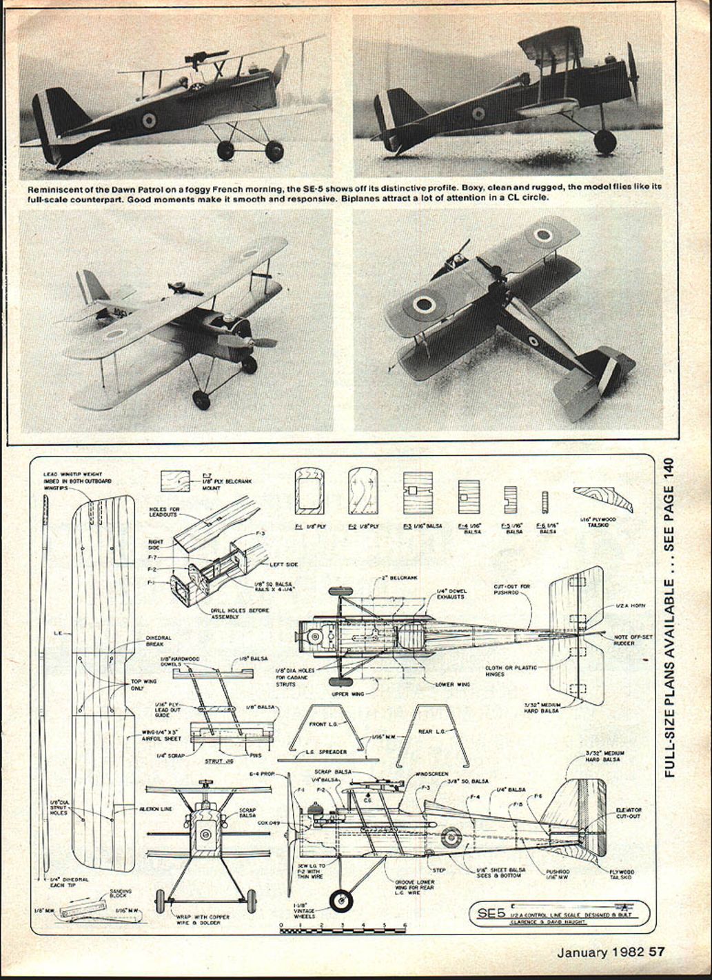
- Slip the leadouts through the guide and bend the ends to suit your method. Use steel wire leadouts for the flying lines since they are safer and more durable than Dacron. Check the leadout guide and control horn frequently for smooth movement.
Final finishing and details
- Give the model five coats of clear dope, sanding well between coats. Give the engine compartment a few extra coats to preserve it from fuel.
- Choose a color scheme. Common colors were olive drab upper surfaces and fuselage with light tan undersides.
- After paint has cured for a few days, add details:
- Make exhaust stacks from 1/4-in. dowels and manifolds from scrap balsa.
- Construct the machine gun from aluminum tube and scrap balsa; paint flat black and epoxy in place.
- Cut the windscreen from clear plastic and epoxy it in place.
- Add a pilot (carved from balsa or a plastic figure) and secure with epoxy.
- Mount wheels, engine and propeller.
- Make wheels from foam or wood, or salvage from a kit.
Balancing, trimming and flying
- After final finishing and assembly, balance the model at the center-of-gravity location shown on the plan. Add wingtip weights if necessary — embedding lead in both wingtips helps lateral balance.
- Check the model for any warps. Steam can remove slight warps from balsa sheet wings: hold the wing flat and pass it over steam, keep it flat until cool, and repeat if needed.
- With the model properly balanced and trimmed, hand-launch for glide tests. Trim stabilizer and rudder as needed.
- Adjust engine thrust line slightly if the model tends to turn under power. Start flying with gentle, low-power flights and trim for a smooth climb and level flight. Reduce downthrust for faster, flatter flights.
- The SE-5 will handle wind reasonably well; avoid flying in very gusty conditions until confident with the model. Several good flights will let you set up the model for combat or scale flying.
Tips and recommendations
- Use 35-ft steel flying lines for the SE-5; 1/2A/1/4A models fly much better on steel than on Dacron, and they last longer.
- Check all hinges, leadouts, and control horns frequently for smooth movement.
- Add out-thrust to the engine if needed to improve first-flight success.
- Be prepared to spend a lot of time flying and trimming — the original model was flown weekly for several years and eventually worn out from enjoyment.
I hope you enjoy building and flying the SE-5 as much as I have.
Transcribed from original scans by AI. Minor OCR errors may remain.

