
Sea Loon
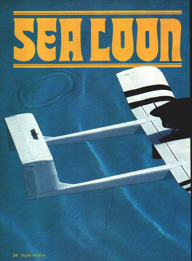
If that lake or large pond nearby has been enticing you for years to use it as the runway for your models, this small flying boat (for a .15-size engine and five-channel radio) may just be the impetus to get you float flying.
A. J. Lennon
Background and configuration
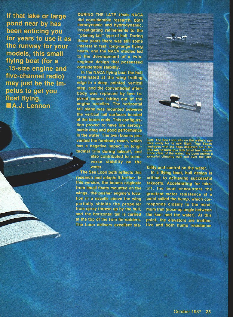
During the late 1940s NACA did considerable aerodynamic and hydrodynamic research into refinements to the "planing tail" type of hull. Their studies led to a twin-engined configuration with twin booms and a high-mounted horizontal tail that produced low aerodynamic drag, good water performance, and improved longitudinal and transverse stability on the water.
The Sea Loon reflects and adapts that research. In this version:
- The booms originate from small wing-mounted floats.
- A pusher engine is mounted in a nacelle above the wing; this partly shields the propeller from spray.
- The horizontal tail is carried at the top of twin fin-rudders.
- The configuration provides excellent stability and control on the water.
Hull and takeoff considerations
Hull design is critical for successful takeoffs. During the takeoff run the hull encounters maximum water resistance at a point called the hump, which corresponds closely to the maximum trim (nose-up angle between the keel and the water). At the hump the elevators are ineffective; both hump resistance and trim must be overcome to become airborne.
Key takeoff characteristics of the Sea Loon:
- At a flight speed near 45 mph and at 0° angle of attack the wing will support the model. Once past the hump, wing lift increases.
- Planing action of the hull and wing lift cause the hull to rise; elevators, aided by the pusher-prop slipstream, become effective. The plane then rides on the hull rear and boom ends; a touch of up-elevator produces takeoff.
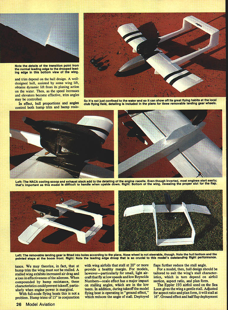
- Drooped 20° wing leading edge with slotted flaps shortens the takeoff run.
- Flaps deployed to 40° permit landings at about 20 mph.
- Flap deployment produces very little change in longitudinal trim.
Important aerodynamic notes:
- A stalled wing at hump trim increases drag and reduces aileron effectiveness; combined with hump resistance this can prevent takeoff, especially with marginal power.
- Full-scale flying boats often have hump trims of ~15° and airfoils that stall at 20°+, but small models flying at low Reynolds numbers have reduced stalling angles (low teens). Ground effect and deployed flaps further reduce stall angle.
- For models, hull design must be tailored to the wing's stall characteristics (which depend on airfoil, aspect ratio, and planform).
The Sea Loon uses the Eppler 193 (E-193) airfoil, which gives a gentle stall. Adjusted for aspect ratio and planform, it will stall at roughly 16°. Ground effect and half-flap deployment reduce the stall angle, so the hull and wing geometry must ensure the wing is not stalled at hump trim.
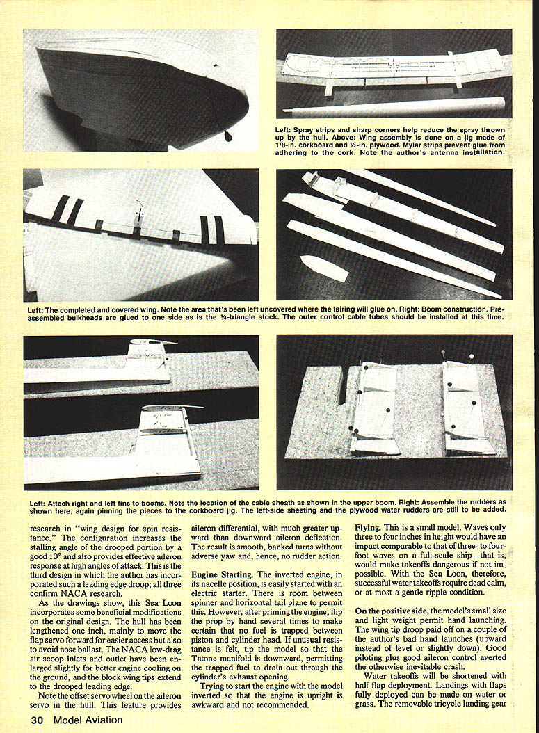
The outboard leading-edge droop incorporated on the Sea Loon increases the stalling angle of the drooped portion by about 10° and provides effective aileron response at high angles of attack. This design is based on NACA research in "wing design for spin resistance" and has been validated by the author on several models.
Beam loading and wing loading
- Sea Loon wing loading: 22 oz per sq ft (wing area).
- Provide beam loading (ounces of weight per inch of maximum beam) commensurate with that wing loading.
- To provide a suitable beam loading for the Sea Loon, a maximum beam of 2½ in. was selected.
Design modifications
Compared with earlier designs, this Sea Loon incorporates the following beneficial changes:
- Hull lengthened by 1 in. to move the flap servo forward for easier access and to avoid nose ballast.
- NACA low-drag air scoop inlets and outlet slightly enlarged for better engine cooling on the ground.
- Block wingtips extend to the drooped leading edge.
- Offset servo wheel on the aileron servo provides aileron differential (greater upward than downward deflection) for smooth banked turns without adverse yaw.
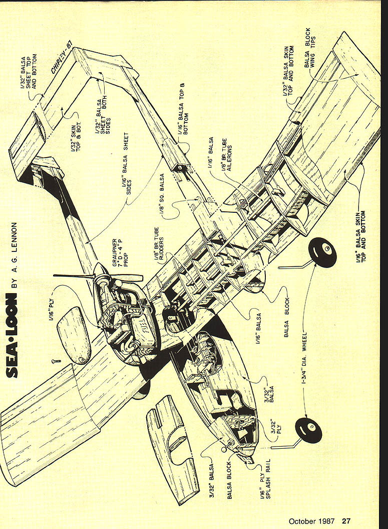
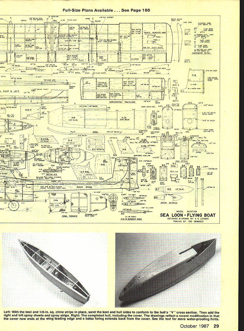
Construction
The Sea Loon's structure is based on a stressed-skin concept. All surfaces are sheet balsa with a minimum of internal components. This construction is light yet surprisingly strong. True lengths for curved surfaces (hull sides, nacelle sides, etc.) are shown on the drawings; build components according to those guidelines. Detailed instructions for major components follow.
Nacelle
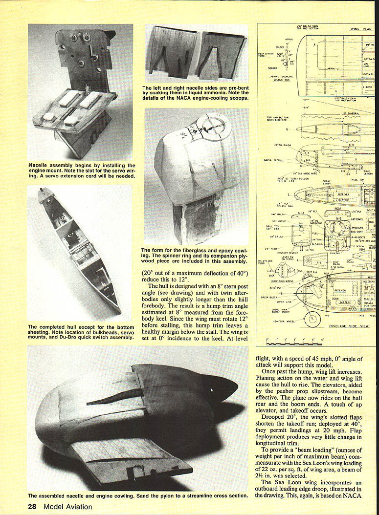
Successful nacelle assembly depends on the correct sequence:
- Assemble the engine mount and cut the slot for the servo wiring.
- Solder the wiring to the Radio Shack jack and mount it on its ply base; epoxy the jack and mount in position.
- Rough-shape the balsa nose block and hollow it out.
- Install bulkhead N1 and add the sides. Install the servo extension cable through the slot in the nacelle strut.
- Using contact cement, attach the fitted tank to the foam pads. Use all three outlet holes in the tank plug—for engine fuel, manifold pressure, and fuel return—and install plumbing as shown. Plug the open end of the fueling tubing with a rivet or small screw.
- Mount the Radio Shack battery holder to the ply base using 5/16 bolts and nuts. Complete soldering of glow-plug wiring connections and epoxy the holder in place.
- Install the servo mount, install the servo, connect it to the servo extension, and mount the engine.
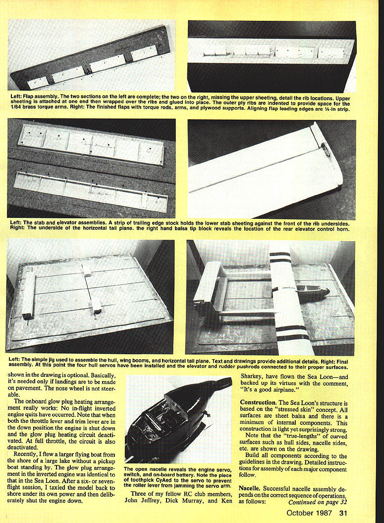
- Connect the .045-in. music-wire pushrod and mini-link clevis to both servo and engine throttle arms. Using cyanoacrylate (CyA), attach the Radio Shack roller lever switch onto the servo as shown.
- Attach nacelle cover components.
- Make the cowling by laying up two layers of medium-weight fiberglass on the form. Assemble the ply spinner ring and companion piece using Hobby Poxy #2. When cured, dissolve the styrofoam core with acetone or gasoline then trim and cut on the parting line.
- Epoxy the top portion of the cowling to bulkhead #2 and align the spinner ring. Position the rear cowl plywood and attach the hold-down assembly with the #2 shoulder screw.
- Install the lower cowling and fit the rear cowl hold-down assembly so the cowl closes properly. To prevent bonding the lower cowl to bulkhead #2, insert waxed paper between the hold-down assembly and the bulkhead.
- Sand the nacelle to final shape.
Hull
- Prebend the hull sides using liquid ammonia. Arrange weights/supports to hold the sides until dry.
- Do the subassembly for bulkheads H1, H2, H4, H4A, and H5.
- Install 3/16-in.-sq. servo mounts and 1/8-in.-sq. balsa on the sides.
- Assemble sides and top front of the bulkheads (with the switch) using clamps as needed.
- Install ply servo mounts and the keel. Install 1/8-in.-sq. balsa at the chines.
- Sand the keel and chines to meet the "V" of the bulkhead bottoms.
- Fit and cement the bottom planking to keel, bulkheads, and chines. Add nose block and sand to shape.
- Add spray strips and sand to the contours shown on the drawing.
- Attach the cover components to the hull and to the radius corners.
Wing
- Assemble the rudder-elevator and aileron torque tubes. Note: the 3/16-in.-dia. elevator tube rides on the 5/32-in.-dia. rudder tube. Solder bushings inside the 3/16-in. tube and complete the hinges.
- Solder 5/32-in.-dia. stops to both sets of tubes to prevent end-play. Support 5/32-in. dia. bearings with 1/16-in. ply plates; epoxy ply and bearings to ribs. Use K&S brass tubing and 1/4-in. brass strips; solder horns securely to tubes.
- Make a jig of 1/4-in. corkboard on 1/2-in. plywood. Cement a 3/32 x 1/8-in. balsa strip to the jig to cater to slight undercamber of the E-193 wing section.
- Mark rib locations on all three lower wing skins and pin skins on the jig. Cement 1/16-in. trailing edges in position.
- Position lower 1/8-in.-sq. spar and all torque tubes on skins; rib cutouts will locate them. Install ribs and epoxy in the ply bearing supports (all seven).
- Add upper 1/8-in.-sq. spar and 1/16-in. balsa webbing between ribs. Add balsa and ply dihedral joint reinforcements and 1/4-in. triangular stock.
- Install three drilled blocks for wing hold-down.
- Install antenna with a brass-tube coupling so the antenna can be disconnected and reconnected without changing overall length (procedure detailed below).
- Install aileron outboard pushrod and clevises on horns and run through ply guides.
- Attach aileron pushrods (3/32-in. dia. music wire) to mini-link clevises using 1/4 in. of threaded portion of 2-56 coupling soldered to the music wire. Tape the mini-link 2-56 to permit adjustment for trim.
- Rear elevator clevis is a shortened mini-link connected to the elevator cable with the 1/4-in. threaded coupling (drilled full length). Carburetor clevis attached to .045-in.-dia. music wire pushrod; drill brass coupling 1/64-in. dia. for the wire.
- Bend and pin the lower wing skin LE to the rib contour and cement.
- Cement center-section upper wing skin to spars and ribs except at the LE. Fit outboard upper skins and cement to spars and ribs except at the LE.
- Hold skins with 1/2-in. masking tape while cement sets.
- Install triangular cross-section strips onto the rear spar in front of both ailerons and flaps; sand to form flap slot lid.
- Install drilled holes for flap torque rod to fit closely to prevent leakage.
Antenna coupling procedure (recommended):
- Measure and cut the antenna four inches from the receiver.
- Solder a 1/16-in. length of 1/16-in. brass tube to each cut end, using heat-shrink tubing over the solder joints.
- Join with a 1/16-in. brass coupling that fits inside 3/32-in. tube. File a small amount of solder onto the 1/16-in. tube to ensure a tight electrical connection while allowing disconnection.
- Re-measure and trim the far end if needed so the final antenna length matches the original.
This allows the receiver to be moved between models without changing antenna length.
Booms
- Assemble bulkheads. If installing landing gear, lace and epoxy a piece of 3/16-in. sq. brass tubing to bulkhead B2.
- Cement 1/4-in. triangular stock and 1/8-in.-sq. strips to the four boom sides.
- Attach bulkheads to boom sides and install plastic tube sheath for elevator and rudder runs.
- Add top and bottom boom sheeting. Note: bottom sheeting has been shortened at the front to permit access to elevator and rudder horns.
- Add pieces B8, B9, B10, and B11. Defer B12 (lower forward skin) to provide access to horns during final assembly.
- Add balsa nose blocks and sand to shape. Sand top corners and add 1/8-in. ply skeg at lower rear end.
Fins
- Install fin spars at the correct angle (92° as shown on the drawing) to the bottom skin.
- Add right-hand skins and ribs R1, R2, and R3. Add R7 on right-hand side and attach elevator tube casing with CyA.
- Add left-hand skins, cement LE liberally and tape as for wing LE. Add blocks R9 and sand LE to radius. Add R4.
Rudders
- Assemble right-hand skins, LE spars, and ribs as shown. Note the 1/16 ply rudder horn/rib.
- Add left-hand skins and sand to shape. Add 1/16 ply water rudder.
Flaps
- Assemble and solder the center 1/16-in. music wire pivot, 3/32-in. brass tube, 1/8-in. inboard horn, two ply flap supports, and two 1/64-in. brass flap horns. Check solder joints for strength.
- Assemble boom 1/16-in. music wire pivots, two ply flap supports, and two 1/64-in. brass horns. Solder carefully.
- Epoxy 1/16-in. music wire outboard pivots into outboard ply flap ribs.
- After covering the flaps (MonoKote recommended), assemble carefully aligning flap leading edges and epoxy 1/64-in. brass horns to ply end ribs. Ensure ply flap supports clear boom sides for free operation.
Ailerons
Assembly is similar to the elevator. Note that the aileron ply inboard rib extends to the aileron LE to provide the aileron horn.
Stabilizer and Elevator
- See photos/drawings for detail. Note the 1/4-in. balsa rib near the right-hand end of the elevator. The 1/16-in.-dia. music wire elevator torque rod is inserted into this rib, and the spar is grooved so the rod is submerged in the balsa structure.
- The elevator brass horn is visible in the photos and is installed as shown.
Covering and installing hinges
- MonoKote covering was used. Leave a generous 1/4-in. overlap at seams to prevent leakage.
- Attach ailerons, rudders, and elevator using the double MonoKote side-hinge procedure to provide hinging and a gap-seal for effective control. Ensure surfaces operate freely both directions.
- Leave underside of wing bare where booms make contact so balsa-to-balsa cementing can take place.
- Cement stabilizer end blocks to the stabilizer and shape them.
Drilling and tapping
- Use the three drilled holes in the wing and the hull and nacelle hold-down blocks to align mating holes in hull and nacelle main blocks.
- Ensure wing and hull alignment is correct before drilling. Same applies to the covers.
- Use a No. 29 drill for 8-32 threads and a No. 50 drill for 2-56, and tap accordingly.
Final assembly
- Install four servos in the hull and attach the five clevis-and-pushrod assemblies to flap, aileron, rudder, and elevator horns protruding from the wing center-section underside.
- Install the wing on the hull. Aileron, elevator, and rudder pushrods pass through the opening provided in bulkhead H3; the flap pushrod passes through bulkheads H3 and H4. Bolt the wing to the hull and install pushrods in the connectors for the appropriate servos.
- Position the wing-hull assembly on a fixture with the keel resting full-length on the board. Install booms, cement liberally to the wing, and align. Add and cement the horizontal tail plane.
- When cement has set, install rudder and elevator pushrods in the booms from the front. Make the connection to the rudder horn with a right-angle bend in the 1/16-in. music-wire pushrods.
- Attach rudder and elevator clevises in the booms to the appropriate horns. Connect rudder levers and outboard elevator rear clevises to the horns.
- Adjust threaded couplings in forward rudder and elevator clevises so that when control surfaces are neutral the forward horns are vertical.
- Add lower boom cover B12 and cover with MonoKote.
- Install the nacelle in its slot in the wing and cement after pulling the engine servo-extension wiring forward into the hull.
- Add wing-strut balsa-block fairings and install upper and lower wing skins and ribs to fill the gap between flap inboard ends.
Sealing
- Use silicone to seal wing-to-hull connections below the wing. Cover openings with MonoKote after adjusting servo-pushrod connections.
- Make a slit in the MonoKote to permit receiver battery-charging jack access; seal the slit with masking tape. Install the hull cover over the MonoKote seal.
Landing gear
- The removable tricycle landing gear shown in the drawings is optional and is needed only for pavement landings. Its installation does not significantly alter CG.
- Where landing-gear legs enter their sockets, melt a bit of solder that can be filed to provide a firm yet easily removable connection.
Exhaust manifold
- The Tatone .099–.19 manifold ends are threaded 2-56 to accept 2-56 nuts; use No. 2 lock washers under the nuts.
- Alternatively, if you have a Dremel and drill press: drill (No. 50) and tap 2-56 the bosses on each side of the engine exhaust (OS Max .15 RC) 1/8-in. deep. Drill corresponding holes in the lower half (engine inverted) of the manifold. Bolt the manifold half directly to the engine with 2-56 bolts (3/8-in. long) and No. 2 lock washers; then install the upper half.
- Plug normal attachment holes with short 4-40 bolts after tapping for 4-40 threads.
- The brass exhaust tube is held in the manifold by a small self-tapping screw inserted in a 1/16-in. hole through both manifold and tube. To bend the brass tube so exhaust does not impinge on the wing, heat to red-hot and bend very carefully to avoid buckling.
Engine starting
- The inverted engine in the nacelle is easily started with an electric starter. There is room between spinner and horizontal tailplane for a starter.
- After priming, flip the prop by hand several times to ensure no fuel is trapped between piston and cylinder head. If unusual resistance is felt, tip the model so the carburetor intake manifold is downward, allowing trapped fuel to drain through the cylinder's exhaust opening.
- Do not try to start the engine with the model inverted such that the engine is upright; this is awkward and not recommended.
- The onboard glow-plug heating arrangement works: no in-flight inverted-engine quits have occurred in the author's use. Note: when both throttle lever and trim lever are down the engine shuts down and the glow-plug heating circuit is deactivated. At full throttle the circuit is also deactivated.
Flying
- This is a small model. Waves only 3–4 in. high would have an impact comparable to 3–4 ft waves on a full-scale ship, making takeoffs dangerous or impossible. Successful water takeoffs require dead calm or at most a gentle ripple.
- The model's small size and light weight permit hand launching. Wing tip droop proved helpful on a few bad hand launches that produced an upward attitude; good aileron control averted crashes.
- Water takeoffs are shortened with half-flap deployment. Landings with flaps fully deployed can be made on water or grass.
- The removable tricycle landing gear is optional; the nose wheel is not steerable.
- The author recently taxied a larger flying boat back to shore under its own power and deliberately shut the engine down; the glow-plug arrangement for inverted engines performed well.
Three fellow RC club members — John Jeffrey, Dick Murray, and Ken Sharkey — have flown the Sea Loon and commented, "It's a good airplane."
Now that you've built your Sea Loon, wait for a day when the water is quiet or barely rippling — and watch her break free of the water's bond. You're going to enjoy this flying boat.
Transcribed from original scans by AI. Minor OCR errors may remain.

