


SEA POWER
The State of Free Flight
If the "Free Flight Community" were to become organized and employ an outside study group to evaluate and report on the "State-of-the-Art" in Free Flight, we would likely be in for a surprise. Such a group would probably report that there is no single state-of-the-art, but rather a giant spectrum spanning a 45-year period or more. Even if we narrow the field — eliminate Old-Timer activity and concentrate on competitive power flying — we still find an incredible variety of equipment in use: everything from docile "Dusters" to automated futuristic "bombs." Isn't this variety part of what makes Free Flight great? Any well-trimmed model, put right and flown consistently, can still finish in the winner's circle.
Free Flight has changed and will continue to change. This promise of change provides the challenge that keeps many fliers interested. Shrinking flying sites have driven many of these changes and prompted new rules for Categories I, II and III. Since performance is the name of the game, new design concepts have been developed to match ever-shortening engine runs: smaller, faster models with more powerful engines have emerged, replacing large slow-climbing floaters with higher-climbing designs that depend on altitude and good air to attain maximum performance. These design parameters have created their own special problems.
Design Trends and Typical Problems
The typical Free Flight model today is a compromise. To maintain a suitable glide requires sufficient angular difference between wing and stabilizer (longitudinal dihedral). This creates a problem during the high-speed power portion of the flight: the model tends to climb in an up-arc which, if allowed to continue, would result in a loop. This condition is typically controlled by inducing a turn, which usually transforms the loop into a spiral climb. The turn also helps alleviate the potential stall at the end of the engine run, providing a smooth transition from power to glide. As more powerful engines are installed on smaller airframes, this condition becomes more difficult — or impossible — to control.
Approaches: Dixielander and VIT-AR
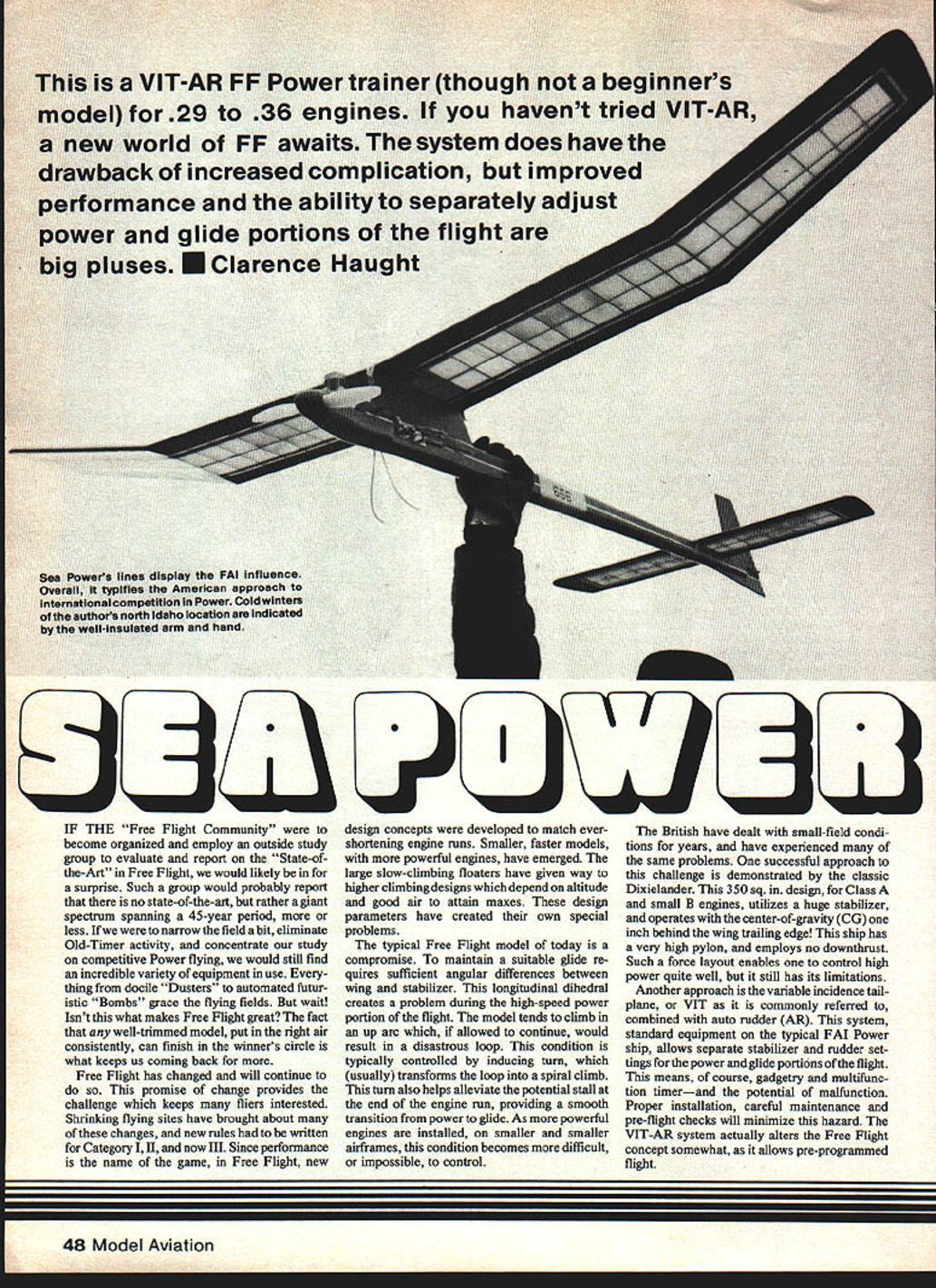
The British have dealt with small-field conditions for years and have experienced many of the same problems. One successful approach is demonstrated by the classic Dixielander: a 350 sq. in. design (for Class A and small B engines) that utilizes a very large stabilizer and operates with the center-of-gravity (CG) one inch behind the wing trailing edge. This ship has a very high pylon and employs no downthrust; such a force layout enables reasonable control under high power but still has limitations.
Another approach is the variable-incidence tailplane (VIT) combined with auto-rudder (AR). This system, standard equipment on the typical FAI power ship, allows separate stabilizer and rudder settings for the power and glide portions of the flight. That means gadgetry, multifunction timers, and the potential for malfunction — but proper installation, careful maintenance and pre-flight checks will minimize that hazard. The VIT-AR system alters the Free Flight concept somewhat by allowing pre-programmed flight. VIT-AR models, once equipped, are actually easier to trim and have a better chance of surviving those crucial first flights.
Sea Power — Purpose and Overview
Sea Power was designed as a VIT trainer using a .29 engine called "Bee Power." The objective was to create a model that would perform well and simultaneously allow the flier to gain experience with programmable tail feathers. The modeler who plans to move into FAI Power will find Sea Power opens useful horizons. Sea Power typifies the state-of-the-art in Free Flight power, but the trainer definitely isn't a beginner's model.
I won't provide a step-by-step glue-stick-A-to-former-B construction sequence. Instead, I will call out particular construction points and spend most of the space on trimming and flying techniques.
Construction and Materials Notes
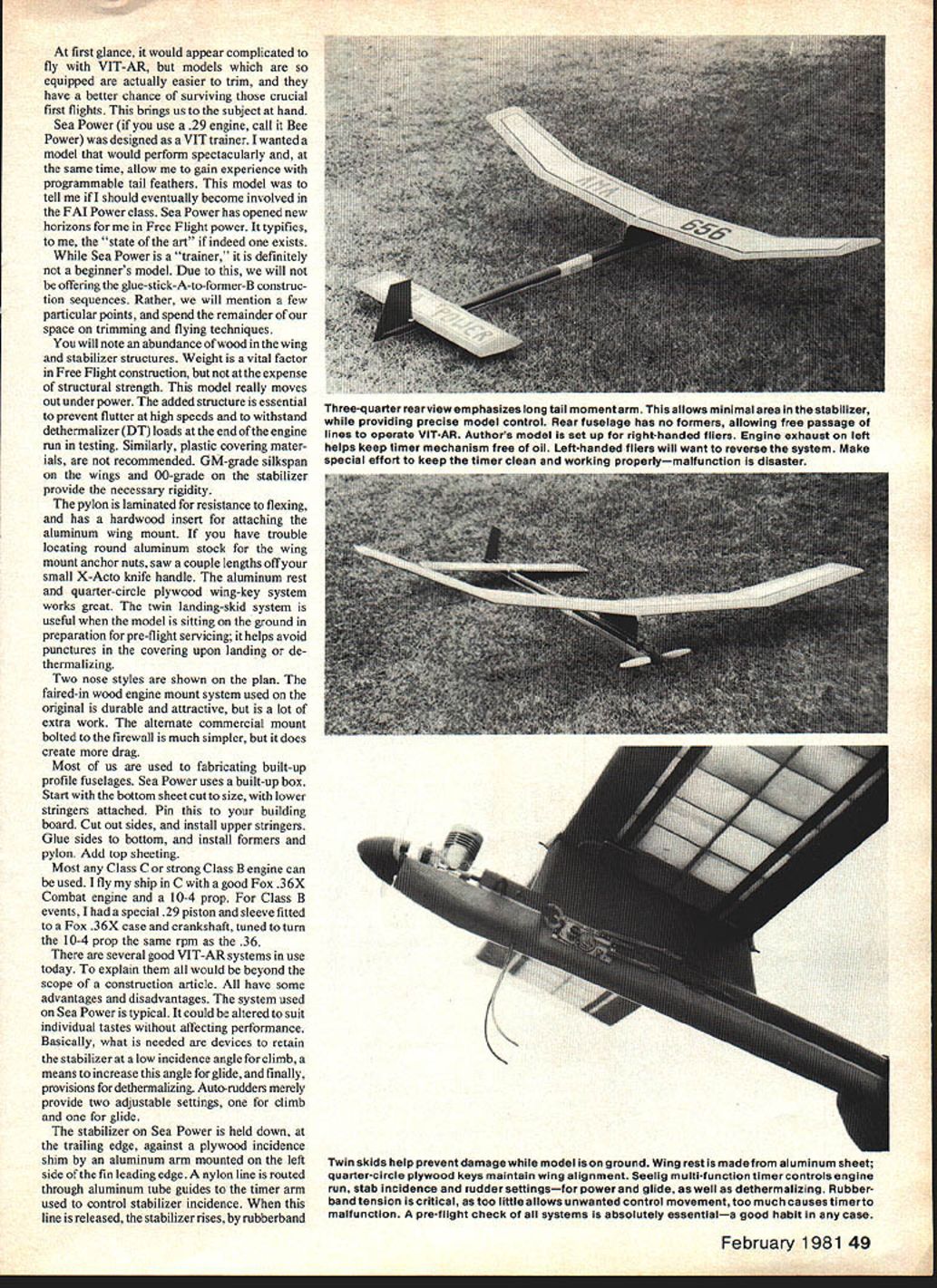
- Note the abundance of wood in the wing and stabilizer structures. Weight is vital in Free Flight construction, but structural strength is more important when the model really moves under power.
- Add structure to prevent flutter at high speeds and to withstand dethermalizer (DT) loads during testing.
- Use plastic covering materials: G.M.-grade silkspan on the wings and 0.00-grade on the stabilizer to provide the necessary rigidity.
- The pylon should be laminated for resistance to flexing and have a hardwood insert for attaching the aluminum wing mount.
- If you have trouble locating round aluminum stock for the wing-mount anchor nuts, saw a couple of lengths off a small X-Acto knife handle.
- An aluminum-rest, quarter-circle plywood wing-key system works well.
- A twin landing-skid system is useful for the model when sitting on the ground; careful preparation and pre-flight servicing help avoid punctures to the covering upon landing and dethermalizing.
- Two nose styles are shown on the plan: the faired-in wooden engine-mount system (durable and attractive, but more work) and an alternate commercial mount bolted to the firewall (simpler but slightly more drag).
Most of us are used to fabricating built-up profile fuselages. Sea Power uses a built-up box fuselage:
- Start with the bottom sheet cut to size and attach lower stringers; pin this to your building board.
- Cut out the sides and install upper stringers.
- Glue sides to bottom, then install formers and pylon.
- Add top sheeting.
Powerplant
Most any Class C or strong Class B engine can be used. I fly my ship in C with a Fox .36X Combat engine and a 10x4 prop. For Class B events, I had a special .29 piston and sleeve fitted to a Fox .36X case and crankshaft, tuned to turn the 10x4 prop at the same RPM as the .36.
VIT-AR System on Sea Power
There are several good VIT-AR systems in use; explaining them all is beyond the scope here. The system used on Sea Power is typical and can be altered to suit individual tastes without affecting performance. Basically, what is needed:
- A device to retain the stabilizer at a low incidence angle for climb.
- A means to increase stabilizer incidence for glide.
- Provisions for dethermalizing.
- Auto-rudder provides two adjustable settings, one for climb and one for glide.
On Sea Power:
- The stabilizer is held down at the trailing edge against a plywood incidence shim by an aluminum arm mounted on the left side of the fin leading edge.
- A nylon line routed through aluminum tube guides connects to the timer arm. When this line is released, the stabilizer rises by rubberband tension to climb settings. To return to glide, the timer pushes the aluminum arm forward to force the stabilizer down to glide incidence.
- The auto-rudder is held against the climb stop (against rubberband tension) by a line to the timer. When this line is released, the rubber tension pulls the rudder over against the glide stop.
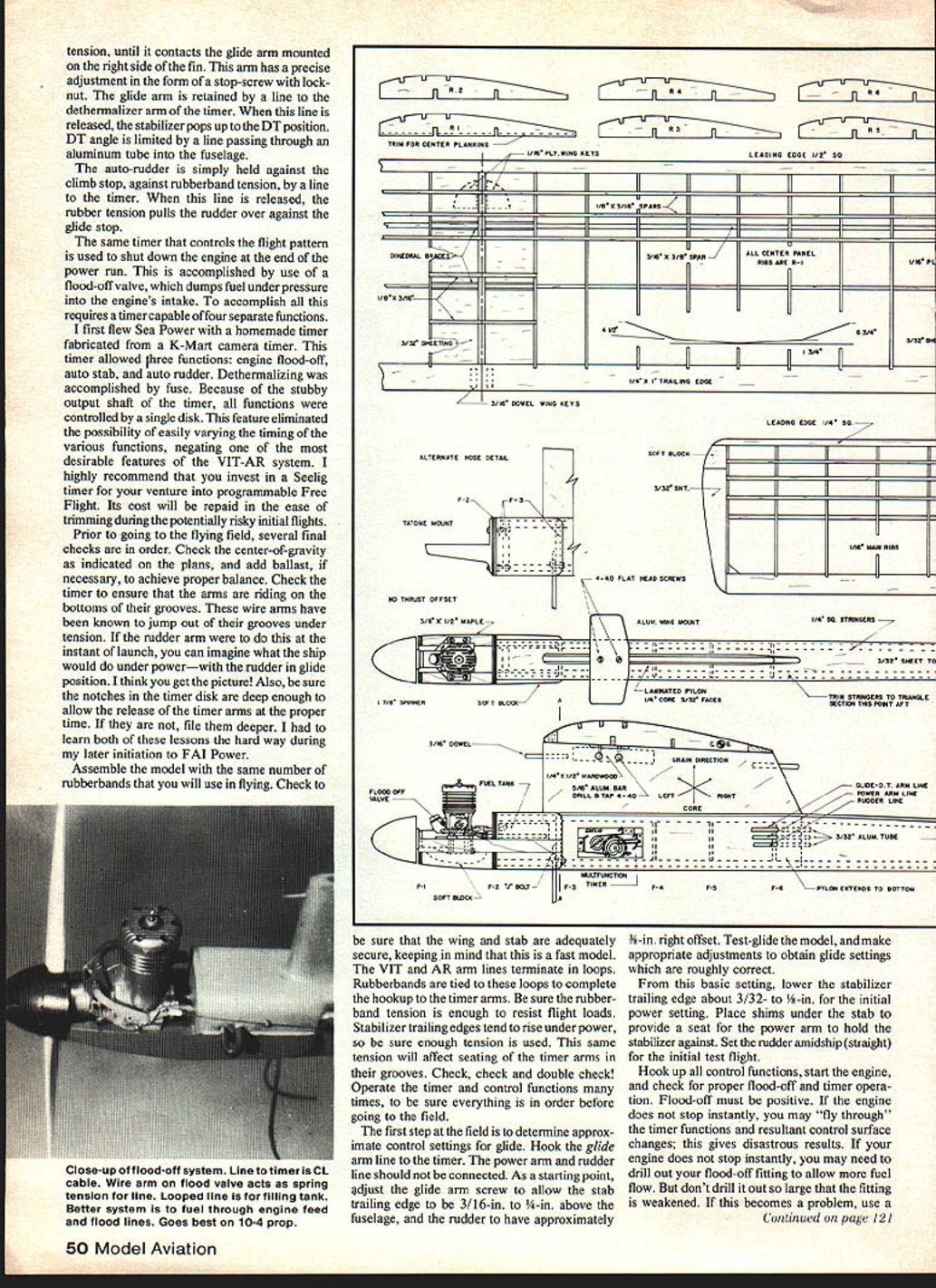
- The same timer that controls the flight pattern is used to shut down the engine at the end of the power run via a flood-off valve that dumps fuel under pressure into the engine's intake. This requires a timer capable of four separate functions.
I first flew Sea Power with a homemade timer fabricated from a K-Mart camera timer. It allowed three functions: engine flood-off, auto-stab and auto-rudder; DT (dethermalizing) was accomplished by fuse. Because of the stubby output shaft of that timer, all functions were controlled by a single disk, which eliminated the possibility of easily varying the timing of the various functions. I highly recommend investing in a Seelig timer for programmable Free Flight: the cost is repaid in the ease of trimming during the risky initial flights.
Pre-flight Checks
Before going to the field, perform several final checks:
- Check the center-of-gravity as indicated on the plans and add ballast if necessary for proper balance.
- Check the timer to ensure that the arms are riding on the bottoms of their grooves; the wire arms have been known to jump out under tension.
- Make sure notches in the timer disk are deep enough to allow release of the timer arms at the proper time; file them deeper if necessary.
- Assemble the model with the same number of rubberbands you will use in flying. Check that wing and stabilizer are adequately secure.
- The VIT and AR arm lines terminate in loops; rubberbands are tied to these loops to complete the hookup to the timer arms. Ensure rubberband tension is sufficient to resist flight loads; stabilizer trailing edges tend to rise under power, so use enough tension to seat the timer arms in their grooves.
- Operate the timer and control functions many times to be sure everything is in order before going to the field.
Initial Trim and Test Flights
- At the field, determine approximate control settings for glide first: hook the glide arm line to the timer but leave the power arm and rudder line disconnected.
- As a starting point, adjust the glide arm screw so the stabilizer trailing edge sits 3/16" to 1/4" above the fuselage and the rudder has approximately 3-1/2" right offset.
- Test-glide the model and adjust to obtain roughly correct glide settings.
- From that basic setting, lower the stabilizer trailing edge about 3/32" to 1/8" for the initial power setting. Place shims under the stabilizer to provide a seat for the power arm to hold the stabilizer against. Set the rudder amidship (straight) for the initial test flight.
- Hook up all control functions, start the engine, and check for proper flood-off and timer operation. Flood-off must be positive — if the engine does not stop instantly, you may "fly through" the timer functions and the resulting control-surface changes; this gives disastrous results.
- If the engine does not stop instantly, you may need to drill out the flood-off fitting to allow more fuel flow — but don't drill it so large the fitting is weakened. If this becomes a problem, use a larger #6 fitting.
- Check for thread security at the flood-off fitting: thread failure will allow the engine to run until fuel is exhausted.
- Repeat the engine cut-off test several times and observe the effects of engine vibration on timer functions. If all is well, you're ready to fly.
Initial flight procedure:
- The first flight should have an engine run of no more than two or three seconds.
- Set the power-arm (stabilizer) timer disk for a 1/2- to 1-second delay after engine cut. Hook the power arm to the timer, but do not hook the glide arm to anything.
- Set the rudder disk for a 3-second delay after the stabilizer releases and hook up the rudder to the timer arm.
- This setup provides an instant DT after engine cut since the glide arm is not held in place. Test-run the timer to ensure adjustments are correct; then hook up lines and perform a visual inspection of all hookups and control positions. Ensure the timer is fully wound.
Launch:
- Start the engine and launch at a 60° to 70° angle — just to the right of the wind.
- Note climb angle and turn tendency. The model should maintain the launch angle and show a slight tendency to turn right.
- Observe DT rate of descent. Correct climb angle by adjusting stab shim height: raise the shim to steepen climb or lower to reduce climb. Adjust rudder if needed.
- If DT is too fast, lower the DT angle slightly.
- Continue 3-second tests until satisfied with climb angle and turn tendency.
When satisfied the power pattern is safe, readjust the timer power-arm disk (stabilizer) for a 3-second delay after engine cut to reduce wing strain as speed builds up in successive flights. Increase the engine run by one second and fly again. Continue increasing engine runs one second at a time, observing the power pattern. Do not hurry this process — make only one small adjustment at a time. Do not attempt to transit into glide until you have attained about a 7-second power run. You may increase the delay for DT if it appears to be placing heavy loads on the wings.
Transition to Glide
When you have a good steep climb (around 65°–70°) and about three-quarters of a turn to the right, you are ready to work on the transition:
- Adjust the DT disk for 15 seconds and hook up the glide and rudder lines. Tension the lines slightly to their respective places.
- Watch the model closely as the engine cuts. The model should transition smoothly.
Common transition problems and causes:
- If the rudder is tripped in (brought in) early, the tail kicks right and the right wing drops, producing a diving turn after engine cut.
- A late rudder can cause stalling.
- Tripping the stabilizer too soon results in upward pitching and a stall.
- Releasing the stabilizer too late allows the model to dive.
When adjusting:
- If the glide is too steep, increase stabilizer incidence or decrease rudder offset.
- If the glide is too flat, decrease stabilizer incidence or increase rudder offset.
- Once a satisfactory glide is achieved, increase engine runs in one-second steps until desired performance is reached. With longer engine runs, it may be necessary to reduce the DT delay slightly to prevent excessive speed at DT.
Operational Tips and Record-keeping
- Sea Power is fairly forgiving and will tolerate small trimming errors, but attention to detail during construction and trimming greatly improves performance.
- The model's high pylon and large stabilizer make it responsive to small changes — take time to understand how each control input affects flight.
- When operating from small fields, err on the side of caution: shorten engine runs and use DT to keep the model aloft rather than trying to power into big heights.
- Keep a log of trim settings, engine runs and weather conditions. Good records speed up trimming in subsequent flights and provide a baseline for future adjustments.
- Be patient; expect to spend several flights finalizing the trim.
Conclusion
Sea Power cleanly demonstrates the merits of the VIT-AR system when properly set up. It provides a forgiving trainer for fliers stepping up to FAI-power ships or for those wanting a controllable, enjoyable Free Flight trainer. Take the time to check, double-check and record your settings — the patience will pay off in consistent, safe flights.
— Haught
Transcribed from original scans by AI. Minor OCR errors may remain.

