
Seamaster Sport 40
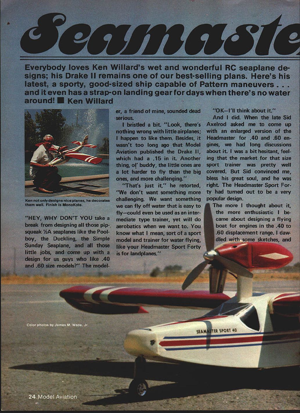
Everybody loves Ken Willard's wet and wonderful RC seaplane designs; his Drake II remains one of our best-selling plans. Here's his latest, a sporty, good-sized ship capable of Pattern maneuvers... and it even has a strap-on landing gear for days when there's no water around! ■ Ken Willard
"Hey, why don't you take a break from designing all those pip-squeak 1/2A seaplanes like the Poolboy, the Duckling, the Simple Sunday Seaplane, and all those little jobs, and come up with a design for us guys who like .40 and .60 size models?" the modeler, a friend of mine, sounded dead serious.
I bristled a bit. "Look, there's nothing wrong with little airplanes; I happen to like them. Besides, it wasn't too long ago that Model Aviation published the Drake II, which had a .15 in it. Another thing, ol' buddy, the little ones are a lot harder to fly than the big ones, and more challenging."
"That's just it," he retorted. "We don't want something more challenging. We want something we can fly off water that is easy to fly—could even be used as an intermediate type trainer, yet will do aerobatics when we want to. You know what I mean, sort of a sport model and trainer for water flying, like your Headmaster Sport Forty is for landplanes."
"OK—I'll think about it." And I did. When the late Sid Axelrod asked me to come up with an enlarged version of the Headmaster for .40 and .60 engines, we had long discussions about it. I was a bit hesitant, feeling that the market for that size sport trainer was pretty well covered. But Sid convinced me, bless his great soul, and he was right. The Headmaster Sport Forty had turned out to be a very popular design.
The more I thought about it, the more enthusiastic I became about designing a flying boat for engines in the .40 to .60 displacement range. I dawdled with some sketches, and suddenly it hit me. Hey, the Headmaster Sport 40 wing, stab, and vertical fin have turned out to be just the right size for .40s and .60s. Why not adapt them to a flying boat hull design? My philosophy on design has always been, "When you've got something that works, don't try to fix it!"
How about going one step further? Let's design the hull so that you can take your wing off your Headmaster Sport Forty and put it on the flying boat hull, without changing the wing in any way. Then, using the plan-form for the stab, elevators, fin and rudder from the Headmaster, make the tail feathers for the flying boat.
Wait a minute! The increased side area of a flying boat hull forward of the center of balance will require a larger vertical tail area. Simple solution: use the fin as is, and increase the rudder area. Let's do it.
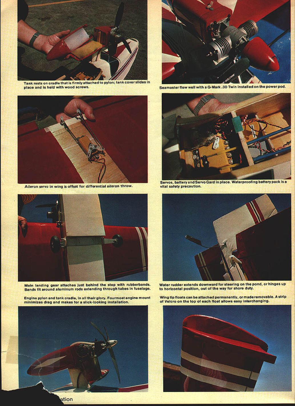
Tank rests on cradle that is firmly attached to pylon; tank cover slides in place and is held with wood screws.
Aileron servo in wing is offset for differential aileron throw.
Main landing gear attaches just behind the step with rubberbands. Bands fit around aluminum rods extending through tubes in fuselage.
Engine pylon and tank cradle, in all their glory. Foremost engine mount minimizes drag and makes for a slick-looking installation.
Seamaster flew well with a G-Mark .30 Twin installed on the power pod.
Servos, battery and ServoGard in place. Waterproofing battery pack is a vital safety precaution.
Water rudder extends downward for steering on the pond, or hinges up to horizontal position, out of the way for shore duty.
Wing tip floats can be attached permanently, or made removable. A strip of Velcro on the top of each float allows easy interchanging.
Since the design is basically a Headmaster Sport Forty that went to sea, what else? Some modelers have access to lakes and ponds; others don't. To make the design amphibious so it can be operated either off water or off a runway depending on what's available, a quickly removable tricycle landing gear was incorporated.
The Seamaster Sport 40 is designed for enthusiasts with .40 to .60 engines who want a model that can be flown off the water and landed easily — easy to build and easy to fly. Incidentally, during the test program the model was also flown with a G-Mark .30 twin. Admittedly, scale performance with the smaller engine is sedate; with .30–.35 power you don't want outside loops. The Seamaster Sport 40 will give very scale-like flights. If you've got .30–.35 and want long, scale-like takeoffs off the water, use the Seamaster. If you've got .60 and want a quick off-water climb and outside loops, take your choice.
So, let's build. Study the plans first. If by chance you already have a Headmaster Sport Forty wing built, use it. If you have to build from scratch, the plans show a very conventional structure. It may be somewhat different from the kit wing since the kit has a preshaped leading edge and trailing edge available. If you've built sport trainers like the Goldberg Falcon, Sig Kommander or RCM 60, the Seamaster wing will present no problems.
If you decide to use a .60 engine and are worried about strength in the center section, that's never a problem — you can cover the center section with 3/4-oz glass cloth before MonoKote; the weight addition will be minor. It's your choice. Since the structure is conventional, study the plans carefully. The plans show servo installation that will yield differential aileron travel; we recommend this setup. If you use equal aileron travel you may have adverse yaw when applying aileron unless you also mix in a bit of rudder. Again, it's your choice.
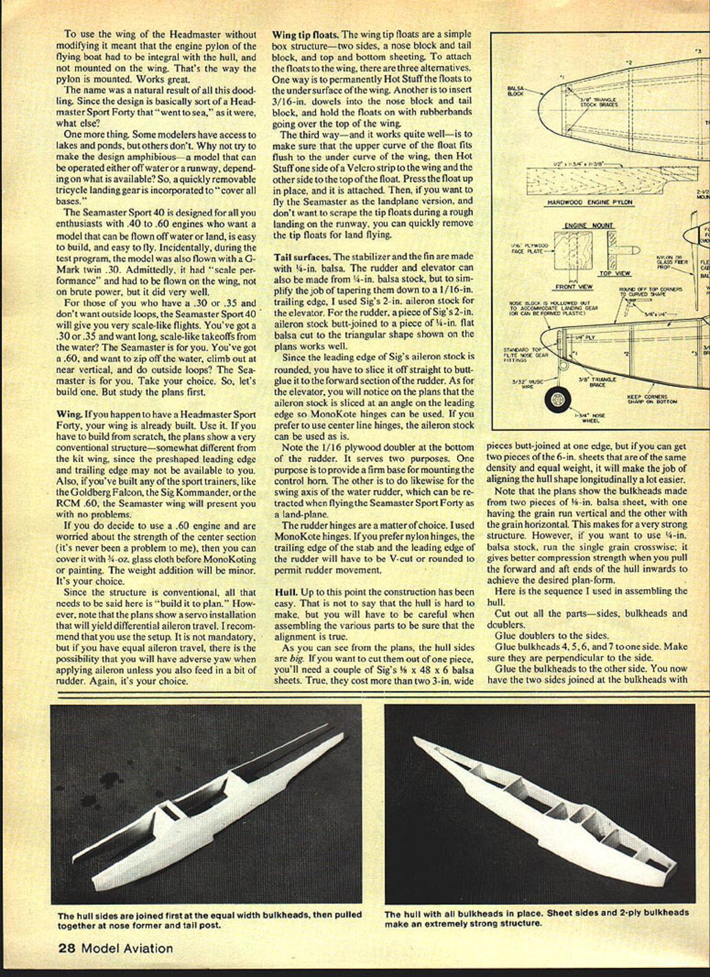
Wing tip floats are a simple box structure — two sides, nose block, tail block, top and bottom sheeting. Attach the floats to the wing in one of three ways:
- Permanently hot-glue the floats to the undersurface of the wing.
- Insert 3/16-in. dowels into the nose block and tail block, and hold the floats on with rubberbands going over the top of the wing.
- Make sure that the upper curve of the float fits flush to the under curve of the wing, then Hot Stuff one side of a Velcro strip to the wing and the other side to the top of the float. Press the float up in place; it is attached but easily removable for land flying.
Tail surfaces
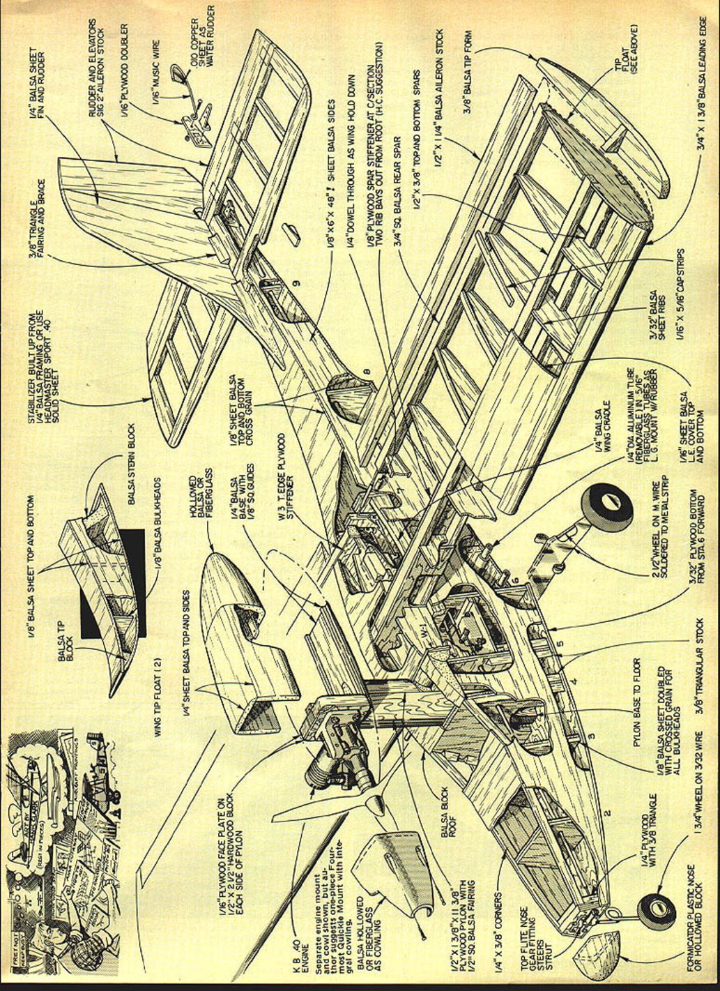
The stabilizer and the fin are made with 1/4-in. balsa. The rudder and elevator can also be made from 1/4-in. balsa stock, but to simplify the job of tapering them down to a 1/16-in. trailing edge, I used Sig's 2-in. aileron stock for the elevator. For the rudder, a piece of Sig's 2-in. aileron stock butt-jointed to a piece of 1/4-in. flat balsa cut to the triangular shape shown on the plans works well.
Since the leading edge of Sig's aileron stock is rounded, you have to slice it off straight to butt-glue it to the forward section of the rudder. As for the elevator, you will notice on the plans that the aileron stock is sliced at an angle on the leading edge so MonoKote hinges can be used. If you prefer to use center-line hinges, the aileron stock can be used as is.
Note the 1/16 plywood doubler at the bottom of the rudder. It serves two purposes: it provides a firm base for mounting the control horn, and it provides a firm mounting for the swing axis of the water rudder, which can be retracted when flying the Seamaster Sport Forty as a landplane.
The rudder hinges are a matter of choice. I used MonoKote hinges. If you prefer nylon hinges, the trailing edge of the stab and the leading edge of the rudder will have to be V-cut or rounded to permit rudder movement.
Hull
Up to this point the construction has been easy. That is not to say that the hull is hard to make, but you will have to be careful when assembling the various parts to be sure that the alignment is true.
As you can see from the plans, the hull sides are big. If you want to cut them out of one piece, you'll need a couple of Sig's 3 x 48 x 6 balsa sheets. True, they cost more than two 3-in. wide pieces butt-jointed at one edge, but if you can get two pieces of the 6-in. sheets that are of the same density and equal weight, it will make the job of aligning the hull shape longitudinally a lot easier.
Note that the plans show the bulkheads made from two pieces of 1/8-in. balsa sheet, with one having the grain run vertical and the other with the grain horizontal. This makes for a very strong structure. However, if you want to use 1/4-in. balsa stock, run the grain crosswise; it gives better compression strength when you pull the forward and aft ends of the hull inwards to achieve the desired plan-form.
Here is the sequence I used in assembling the hull:
- Cut out all the parts — sides, bulkheads and doublers.
- Glue doublers to the sides.
- Glue bulkheads 4, 5, 6, and 7 to one side. Make sure they are perpendicular to the side.
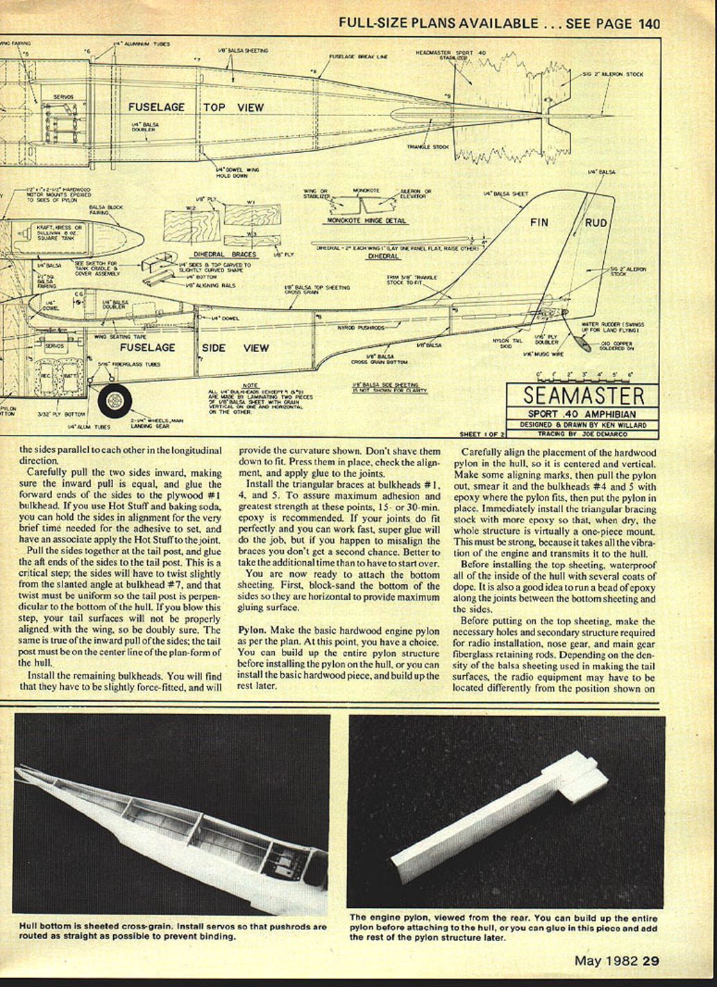
- Glue the bulkheads to the other side. You now have the two sides joined at the bulkheads with the nose former and tail post.
- Install the nose formers and other shaping blocks to provide the curvature shown. Don't shave them down to fit. Press them in place, check the alignment, and apply glue to the joints.
- Install the triangular braces at bulkheads #1, 4, and 5. To assure maximum adhesion and greatest strength at these points, 15- or 30-min. epoxy is recommended. If your joints fit perfectly and you can work fast, CA (super glue) will do the job, but epoxy gives you a margin for realignment.
You are now ready to attach the bottom sheeting. First, block-sand the bottom of the sides so they are horizontal to provide maximum gluing surface.
Pylon. Make the basic hardwood engine pylon as per the plan. At this point, you have a choice. You can build up the entire pylon structure before installing the pylon on the hull, or you can install the basic hardwood piece and build up the rest later.
Carefully align the placement of the hardwood pylon in the hull so it is centered and vertical. Make some aligning marks, then pull the pylon out, smear it and the bulkheads #4 and 5 with epoxy where the pylon fits, then put the pylon in place. Immediately install the triangular bracing stock with more epoxy so that, when dry, the whole structure is virtually a one-piece mount. This must be strong, because it takes all the vibration of the engine and transmits it to the hull.
Before installing the top sheeting, waterproof all of the inside of the hull with several coats of dope. It is also a good idea to turn a bead of epoxy along the joints between the bottom sheeting and the sides.
Before putting on the top sheeting, make the necessary holes and secondary structure required for radio installation, nose gear, and main gear fiberglass retaining rods. Depending on the density of the balsa sheeting used in making the tail surfaces, the radio equipment may have to be located differently from the position shown on the plan. Check the center of gravity; ballast may be needed in the nose.
It is a good idea at this point to temporarily assemble the model with the major weight factors (engine, radio, batteries, gear, etc.) in place to see what variations (if any) will be needed to balance the model at the point shown on the plans. Make allowances for the additional weight in the aft section due to covering, hinges, horns, etc.
Install the flexrods for the nose gear, tail surfaces and engine control. The engine control is a bit tricky; the cable has to go through a fairly sharp bend and must be anchored to keep it from buckling. Operate the control, and use small bracing blocks wherever you note any tendency for the cable to buckle. You'll probably curse this a couple of times, but if you have a better method, use it. This is the way I did it—not necessarily the only way.
Put on the top sheeting. Here, again, first block-sand the top of the sides so they are horizontal. Add the balsa fairing blocks alongside the pylon. Sand the corners round as shown in the detail forward of the wing—only on the top. The bottom corners must be kept sharp for good planing action on the water.
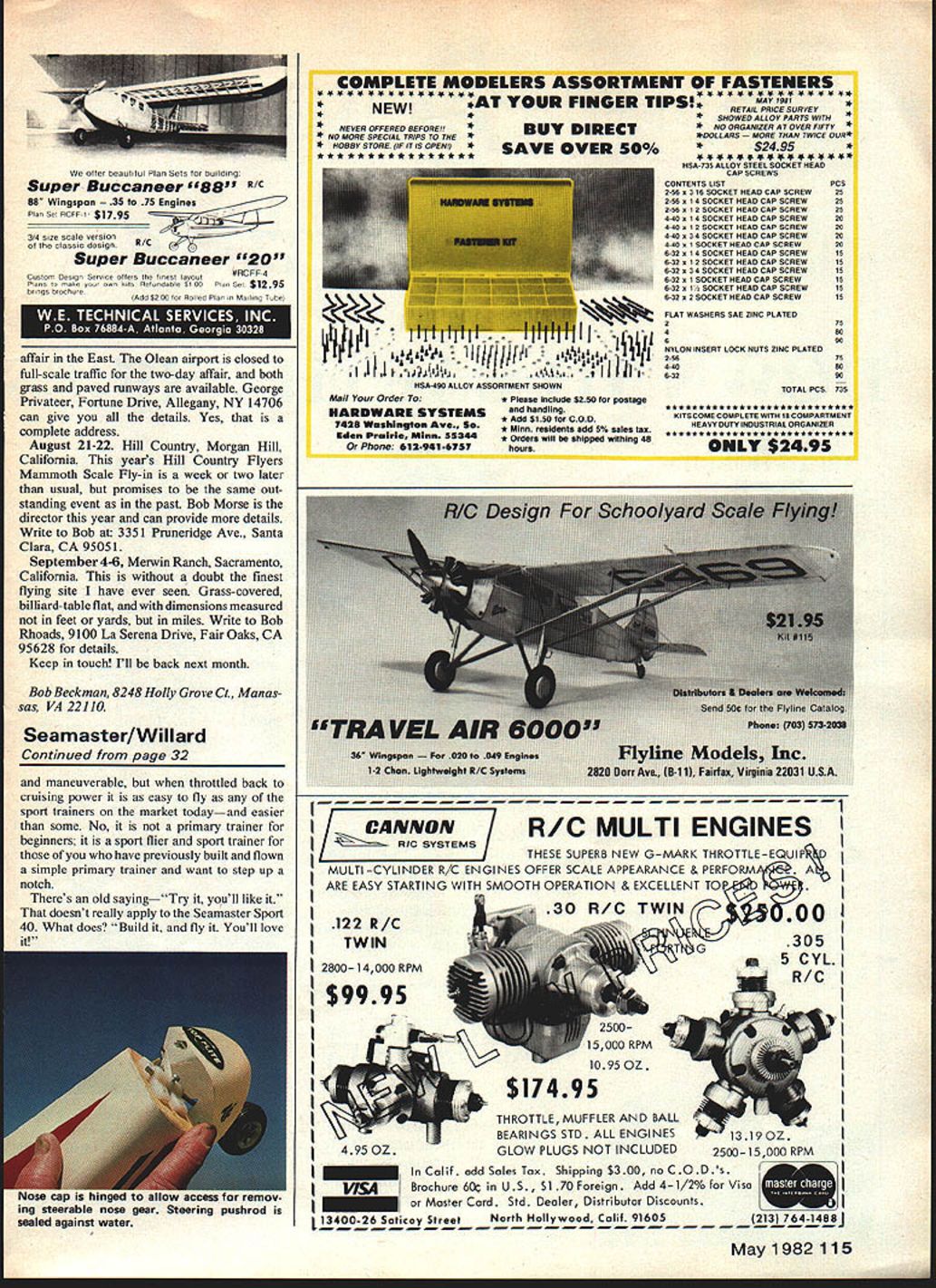
Make the nose block. If you don't want the model to be amphibious, the block can be solid. Otherwise, hollow it out as required to accommodate the nose gear. On my prototype, I carved a nose block, then formed a plastic nose cone using the Formicator (made by Idea Development). It slides on and off easily, and can be held in place with one small wood screw.
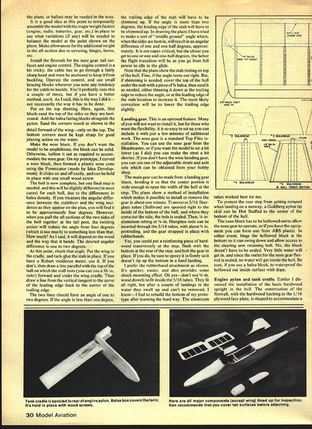
The hull is now complete, but one final step is needed, and this will be slightly different (in most cases) for each hull, due to the differences in balsa density. If you measure the angular difference between the stabilizer and the wing incidence as they appear on the plan, you will find it to be approximately four degrees. However, when you pull the aft sections of the two sides of the hull together at the tail post, the twisting action will reduce the angle from four degrees (which is too much) to something less than that. How much? It will depend on the wood and the way that it bends. The desired angular difference is one to two degrees.
At this point, check that angle. Put the wing in the cradle, and tack-glue the stab in place. If you have a Robart incidence meter, use it. If you don't, draw a line parallel with the top of the hull on which the stab rests (you can use a 36-in. ruler) forward and under the wing cradle. Then draw a line from the vertical tangent to the curve of the leading edge back to the center of the trailing edge.
The two lines should form an angle of one to two degrees. If the angle is less than one degree, the trailing edge of the stab will have to be shimmed up. If the angle is more than two degrees, the leading edge of the stab will have to be shimmed up. In drawing the plans I have tried to make a sort of "middle ground" angle which, when the sides are bent in, will result in an angular difference of one and one-half degrees, approximately. It is not super-critical, but the closer you get to one or one and one-half degrees, the better the flight transition will be as you go from full power to idle in the glide.
Note that the plans show the stab resting on top of the hull. Fine, if the angle turns out right. But, if shimming is needed, cover the top of the hull under the stab with a piece of 1/8-in. balsa, then sand it as needed, either thinning it down at the trailing edge to reduce the angle, or at the leading edge of the stab location to increase it. The most likely correction will be to lower the trailing edge slightly.
Landing gear
This is an optional feature. Many of you will not want to install it, but for those who want the flexibility, it is so easy to set up you can include it with just a few minutes of additional work. The nose gear is a standard Top Flite installation. You can use the nose gear from the Headmaster, or if you want the model to set a bit lower (as I did) you can make the strut a bit shorter. If you don't have the wire-bending gear, you can use one of the adjustable struts and axle sets which can be obtained from your hobby shop.
The main gear can be made from a landing gear blank, bending it so that the center portion is wide enough to span the width of the hull at the step. The plans show a method of installation which makes it possible to install or remove the gear in about one minute. Transverse 5/16-in. fiberglass tubes (Sullivan) are epoxied right to the inside of the bottom of the hull, and where they come out the side, the hole is sealed. Then, 1/4-in. aluminum tubing or 3/8-in. fiberglass rods can be inserted through the 5/16 tubes, with about 1/2 in. protruding, and the gear strapped in place with rubberbands.
Yes, you could put a reinforcing piece of hardwood transversely at the step, flush with the bottom at the rear of the step, and bolt the gear in place. If you do, be sure to epoxy it in firmly so it doesn't rip up the bottom in a hard landing.
I prefer the rubberband attachment as shown. It's quicker, easier, and also provides some shock-mounting effect. Oh yes—don't use 1/4-in. wood dowels to fit inside the 5/16 tubes. They fit all right, but after a couple of landings in the water they swell up and can't be removed. I know—I had to rebuild the bottom of my prototype after learning the hard way. The aluminum tubes worked best for me.
To protect the rear step from getting scraped when landing on a runway, a Goldberg nylon tip skid can be Hot Stuffed to the center of the bottom of the hull.
The nose block has to be hollowed out to allow the nose gear to operate, or if you have the equipment you can form one from ABS plastic. In either event, hinge the hollowed block at the bottom so it can swing down and allow access to the steering arm retaining bolt. No, the block doesn't have to be sealed. Very little water will get in, and since the outlet for the nose gear flexrod is sealed, no water will get inside the hull. Be sure, if you use a balsa block, to waterproof the hollowed out inside surface with dope.
Engine pylon and tank cradle
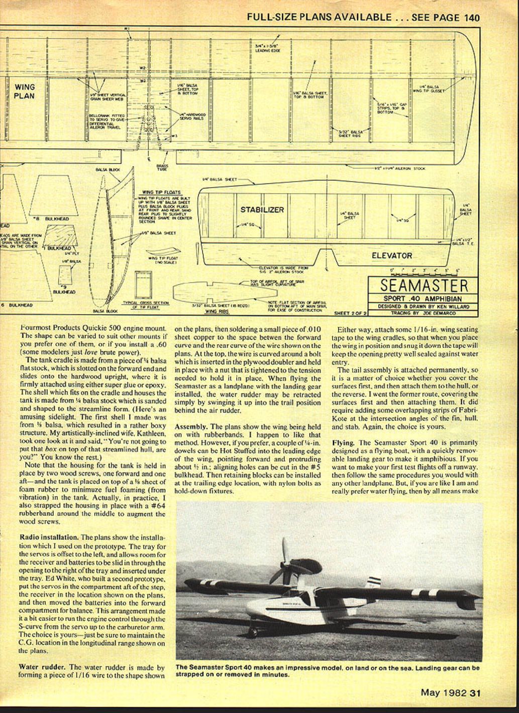
The construction of the firewall, with the hardwood backing to the 1/16-in. plywood face plate, is shaped to accommodate a Fourmost Products Quickie 500 engine mount. The shape can be varied to suit other mounts if you prefer one of them, or if you install a .60 (some modelers just love brute power).
The tank cradle is made from a piece of 1/4-in. balsa flat stock, which is slotted on the forward end and slides onto the hardwood upright, where it is firmly attached using either CA or epoxy. The shell which fits on the cradle and houses the tank is made from 1/8-in. balsa stock which is sanded and shaped to the streamline form. The housing for the tank is held in place by two wood screws, one forward and one aft—and the tank is placed on top of a 1/8-in. sheet of foam rubber to minimize fuel foaming (from vibration) in the tank. In practice, I also strapped the housing in place with a #64 rubberband around the middle to augment the wood screws.
Radio installation
The plans show the installation used on the prototype. The tray for the servos is offset to the left, and allows room for the receiver and batteries to be slid in through the opening to the right of the tray and inserted under the tray. Ed White, who built a second prototype, put the servos in the compartment aft of the step, put the receiver in the location shown on the plans, and then moved the batteries into the forward compartment for balance. This arrangement made it a bit easier to run the engine control through the S-curve from the servo up to the carburetor arm.
The choice is yours—just be sure to maintain the C.G. location in the longitudinal range shown on the plans.
Water rudder
The water rudder is made by forming a piece of 1/16-in. wire to the shape shown on the plans, then soldering a small piece of .010-in. sheet copper to the space between the forward curve and the rear curve of the wire shown on the plans. At the top, the wire is curved around a bolt which is inserted in the plywood doubler and held in place with a nut that is tightened to the tension needed to hold it in place. When flying the Seamaster as a landplane with the landing gear installed, the water rudder may be retracted simply by swinging it up into the trail position behind the air rudder.
Assembly
The plans show the wing being held on with rubberbands. I happen to like that method. However, if you prefer, a couple of 1/4-in. dowels can be Hot Stuffed into the leading edge of the wing, pointing forward and protruding about 1/2 in.; aligning holes can be cut in the #5 bulkhead. Then retaining blocks can be installed at the trailing edge location, with nylon bolts as hold-down fixtures.
Either way, attach some 1/16-in. wing seating tape to the wing cradles, so that when you place the wing in position and snug it down the tape will keep the opening pretty well sealed against water entry.
The tail assembly is attached permanently, so it is a matter of choice whether you cover the surfaces first, and then attach them to the hull, or the reverse. I covered the surfaces first and then attached them. It did require adding some overlapping strips of Fabri-Kote at the intersection angles of the fin, hull, and stab. Again, the choice is yours.
Flying
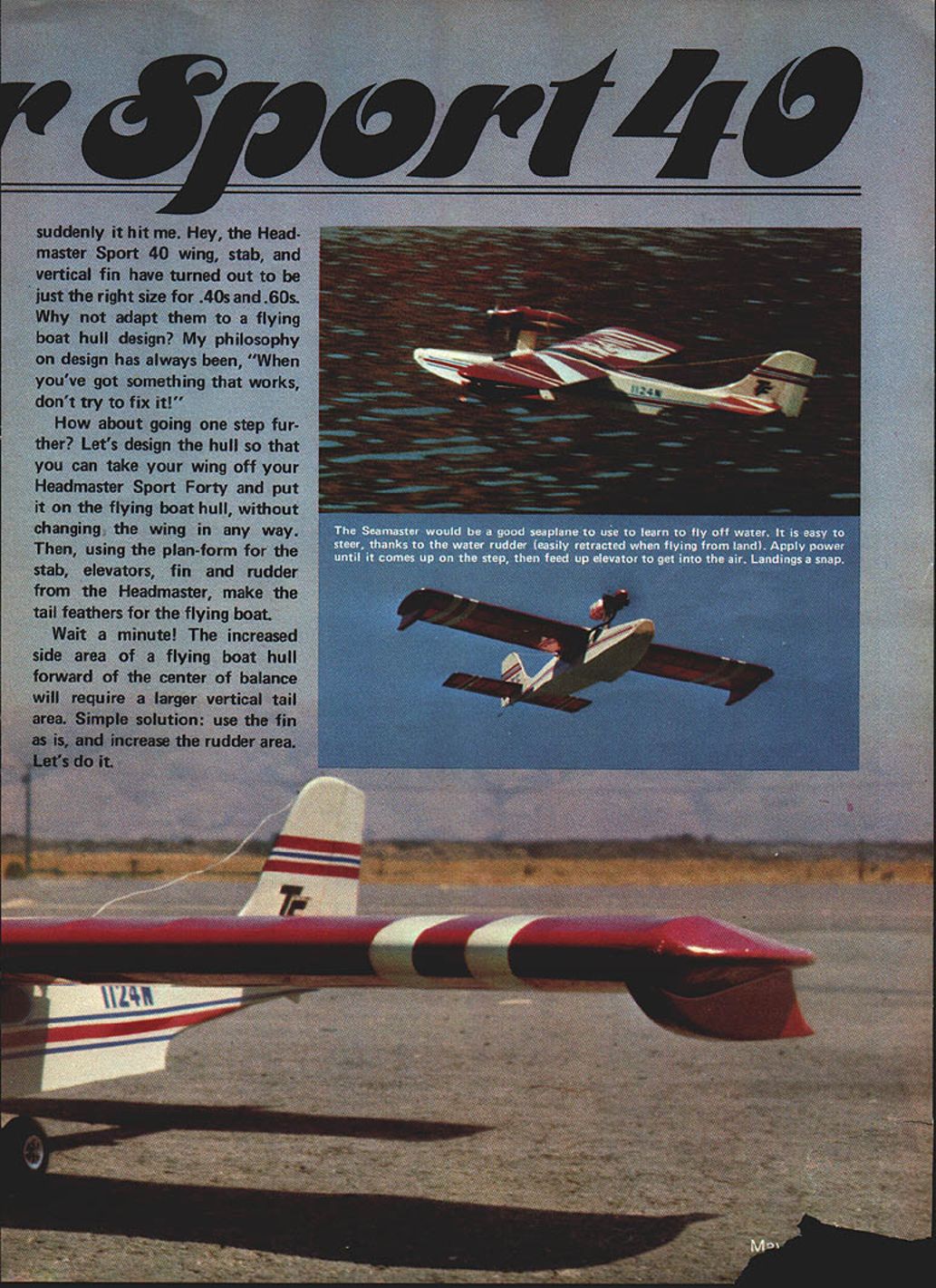
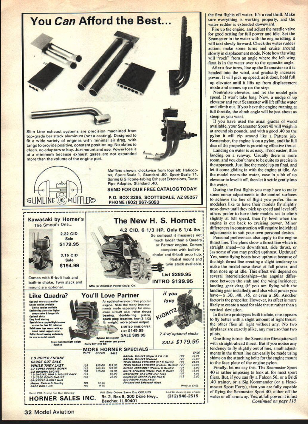
The Seamaster Sport 40 is primarily designed as a flying boat, with a quickly removable landing gear to make it amphibious. If you want to make your first test flights off a runway, then follow the same procedures you would with any other landplane. But, if you are like I am and really prefer water flying, then by all means make your first flights from the water. It's a real thrill. Make sure everything is working properly, and the water rudder is extended downward.
Fire up the engine, and adjust the needle valve for a good setting for full power and idle. Set the Seamaster in the water with the engine idling; it will taxi slowly forward. Check the water-rudder action: make some turns and cruise around slowly in displacement mode. Note how the wing will "rock" from an angle where the left wing float is in the water over to the opposite angle.
After a few turns, line up the Seamaster so it is headed into the wind, and gradually increase power. It will pick up speed; as it does, hold full up elevator until it lifts up from displacement mode and comes up on the step.
Neutralize elevator, and let the model gain speed. It won't take long. Now, a nudge of up elevator and your Seamaster will lift off the water and climb out. If you have the engine running at full throttle, the climb angle will be just about as steep as you want.
If you have used the usual grades of wood available, your Seamaster Sport 40 will weigh in at around six pounds, and with a good .40 on the pylon it will zip around like a Pattern job. Remember, the engine is on a pylon, and the full disc of the propeller is providing effective thrust.
Landing on water is as easy, if not easier, than landing on a runway. Usually there is more room, and you don't have to be quite so precise in the approach. Just line the model up on final, and let it come gliding in with the engine at idle. As the model nears the water, ease in a bit of up elevator to level it off, then let it settle gently into the water.
During the first flights you may have to make some minor adjustments to the control surfaces to achieve the line of flight you prefer. Some modelers like to have their models fly slightly nose-down until they pick up speed and level off; others prefer to have their models set to climb slightly at full speed, then fly level when the engine is cut back to cruising power. Minor differences in construction will require individual adjustments to suit your own personal desires.
Personal preferences also apply to the engine thrust line. The plans show a thrust line which is straight ahead—no downthrust, side thrust, or (as some of you may prefer) upthrust. Upthrust? Yes, some flying boats have upthrust because of the high thrust line creating a slight tendency to make the model nose down at full power, and then nose up at idle. This effect will depend on several interrelationships—the wing incidence, the distance between the stab and the wing, landing-gear drag (if you are flying with the landing gear installed); and also what power you have—.30, .40, .45, or even a .60. Another factor is the propeller. However, its effect is more likely to create a need for side thrust rather than a vertical deviation.
In the two prototypes built to date, one appears to fly better with a slight amount of right thrust, the other flies all right without any. No two airplanes are exactly alike, any more so than two pilots.
One thing is true: the Seamaster flies quite well with straight-ahead thrust. But if you notice any tendency to fly slightly out of line, small adjustments in the thrust line can easily be made using shims on the attaching bolts for the engine pylon.
Finally, let me say this. The Seamaster Sport 40 is rather imposing to look at, for most sport fliers. But, if you can fly a Falcon 56, or a Birdie .40 trainer, or a Sig Kommander (or a Headmaster Sport Forty), then you are fully capable of flying the Seamaster Sport 40, either off the water or off a runway. Yes, at full power, it is fast and maneuverable, but when throttled back to cruising power it is as easy to fly as any of the sport trainers on the market today—and easier than some. No, it is not a primary trainer for beginners; it is a sport flier and sport trainer for those of you who have previously built and flown a simple primary trainer and want to step up a notch.
There's an old saying—"Try it, you'll like it." That doesn't really apply to the Seamaster Sport 40. What does? "Build it, and fly it. You'll love it!"
Transcribed from original scans by AI. Minor OCR errors may remain.

