
Seastrutz
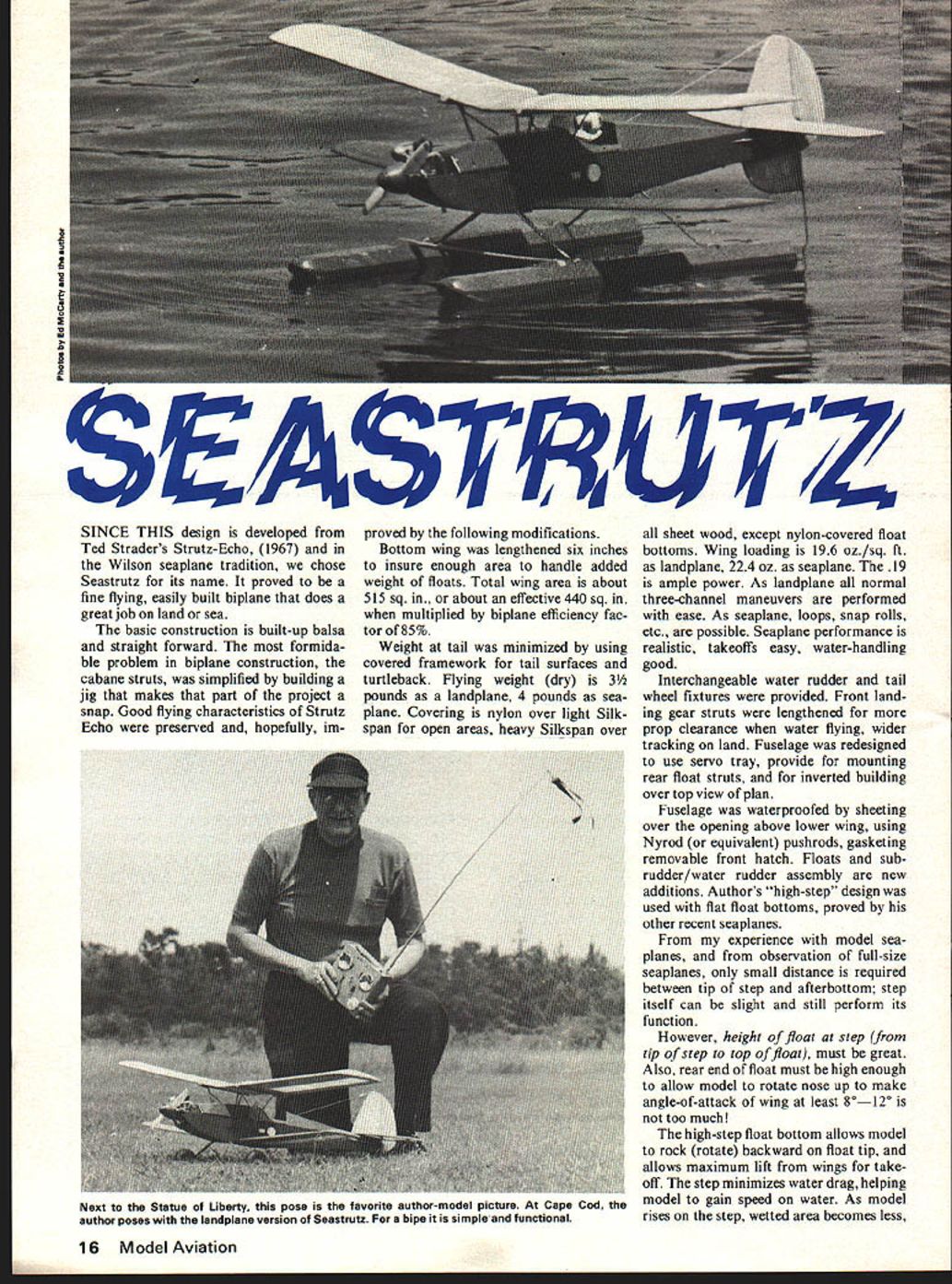
SINCE THIS design is developed from Ted Strader's Strutz-Echo, (1967) and in the Wilson seaplane tradition, we chose Seastrutz for its name. It proved to be a fine flying, easily built biplane that does a great job on land or sea.
The basic construction is built-up balsa and straight forward. The most formidable problem in biplane construction, the cabane struts, was simplified by building a jig that makes that part of the project a snap. Good flying characteristics of Strutz Echo were preserved and, hopefully, improved by the following modifications.
Bottom wing was lengthened six inches to insure enough area to handle added weight of floats. Total wing area is about 515 sq. in., or about an effective 440 sq. in. when multiplied by biplane efficiency factor of 85%.
Weight at tail was minimized by using covered framework for tail surfaces and turtleback. Flying weight (dry) is 3½ pounds as a landplane, 4 pounds as seaplane. Covering is nylon over light Silkspan for open areas, heavy Silkspan over all sheet wood, except nylon-covered float bottoms. Wing loading is 19.6 oz./sq. ft. as landplane, 22.4 oz. as seaplane. The .19 is ample power. As landplane all normal three-channel maneuvers are performed with ease. As seaplane, loops, snap rolls, etc., are possible. Seaplane performance is realistic, takeoffs easy, water-handling good.
Interchangeable water rudder and tail wheel fixtures were provided. Front landing gear struts were lengthened for more prop clearance when water flying, and wider tracking on land. Fuselage was redesigned to use servo tray, provide for mounting rear float struts, and for inverted building over top view of plan.
Fuselage was waterproofed by sheeting over the opening above lower wing, using Nyrod (or equivalent) pushrods, gasketing removable front hatch. Floats and sub-rudder/water rudder assembly are new additions. Author's "high-step" design was used with flat float bottoms, proved by his other recent seaplanes.
From my experience with model seaplanes, and from observation of full-size seaplanes, only small distance is required between tip of step and afterbottom; step itself can be slight and still perform its function.
However, height of float at step (from tip of step to top of float), must be great. Also, rear end of float must be high enough to allow model to rotate nose up to make angle-of-attack of wing at least 8°–12°. It is not too much!
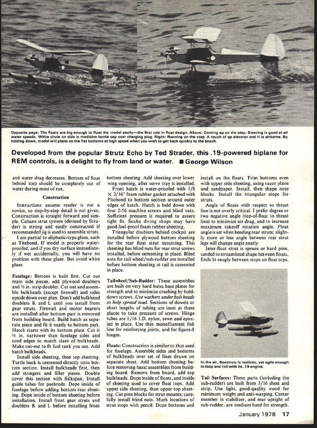
The high-step float bottom allows model to rock (rotate) backward on float tip, and allows maximum lift from wings for takeoff. The step minimizes water drag, helping model to gain speed on water. As model rises on the step, wetted area becomes less, water drag decreases. Bottom float behind step should be completely out of the water during the run.
Construction instructions assume the reader novice; step-by-step detail is given. Construction is straightforward and simple. Cabane strut system devised by Strader is strong and easily constructed. Recommended jig is used to assemble struts. Use partial aliphatic-type glues such as Titebond. When model is properly waterproofed, a dry surface immediately wet accidentally will have no problem. Avoid white glues.
Fuselage
Bottom built first. Cut out main side pieces, add plywood doublers. Cut out and assemble bulkheads except firewall; place sides upside down over plan. Don't add bulkhead doublers K, L until installing front gear struts. Firewall and motor bearers installed after bottom part is removed from building board. Build hatch as a separate piece; fit neatly to bottom part. Hatch starts its bottom plate. Cut V's in narrower fuselage sides; sand edges to match slant of bulkheads. Make cut-out to fit fuel tank. Add hatch bulkheads. Install side sheeting and top sheeting. Turtleback cemented directly onto bottom section. Install bulkheads first; add stringers and filler pieces. Double-cover section with Silkspan. Install guide tubes for pushrods. Dope inside fuselage before adding bottom rear sheeting. Dope inside bottom sheeting before installation. Install front gear struts doublers K, L before installing front gear. and water drag decreases. Bottom of float behind step should be completely out of water during most of run.
bottom sheeting. Add sheeting over lower wing opening, after servo tray is installed.
Front hatch is water-proofed with 1/8 x 3/16" foam rubber gasket attached with Pliobond to bottom section around outer edges of hatch. Hatch is held down with four 2-56 machine screws and blind nuts. Sufficient pressure is required to assure tight fit. Scuba diving shops may have good fuel-proof foam rubber sheeting.
Triangular doublers behind cockpit are installed before plywood bottom sheeting for the rear float strut mounting. This sheeting has blind nuts for rear strut screws installed, before cementing in place. Blind nuts for tail wheel/sub-rudder are installed before bottom sheeting at tail is cemented in place.
Tailwheel/Sub-Rudder:
These assemblies are built on very hard balsa base plates for strength and to minimize crushing by hold-down screws. Use washers under bolt heads to help spread load. Sections of dowels or short lengths of tubing are inset at these places to take pressure of screws. Hinge tubes are 1/16 I.D. nylon, sewn and epoxied in place. Use thin monofilament fish line for reinforcing joints, and for figure-8 hinges.
Floats:
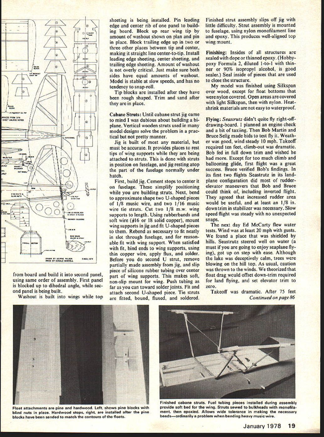
Construction is similar to that used for fuselage. Assemble sides and bottoms of bulkheads over set of lines drawn on separate sheet. Add bottom sheeting before removing basic assemblies from building board. Remove from board, add top bulkheads. Dope inside of floats, and inside of sheeting used to cover float tops. Add upper side sheeting, then upper top sheeting. Cut pine blocks for strut mounts; carefully install blind nuts. Mark locations of strut stops with pencil. Dope bottoms and install on the floats. Trim bottoms even with upper side sheeting, using razor plane and sandpaper. Install, then shape nose blocks. Install the triangular stops for struts.
Angle of floats with respect to thrust line is not overly critical. I prefer a degree or two negative angle (top-of-float to thrust line) to minimize air drag, and to increase maximum takeoff rotation angle. Float angle is set when bending rear struts; slightly more or less angle between rear strut legs will change angle neatly.
Inter-float strut is spruce or hard pine, sanded to streamlined shape between floats. Ends fit snugly between stops on float tops.
Tail Surfaces:
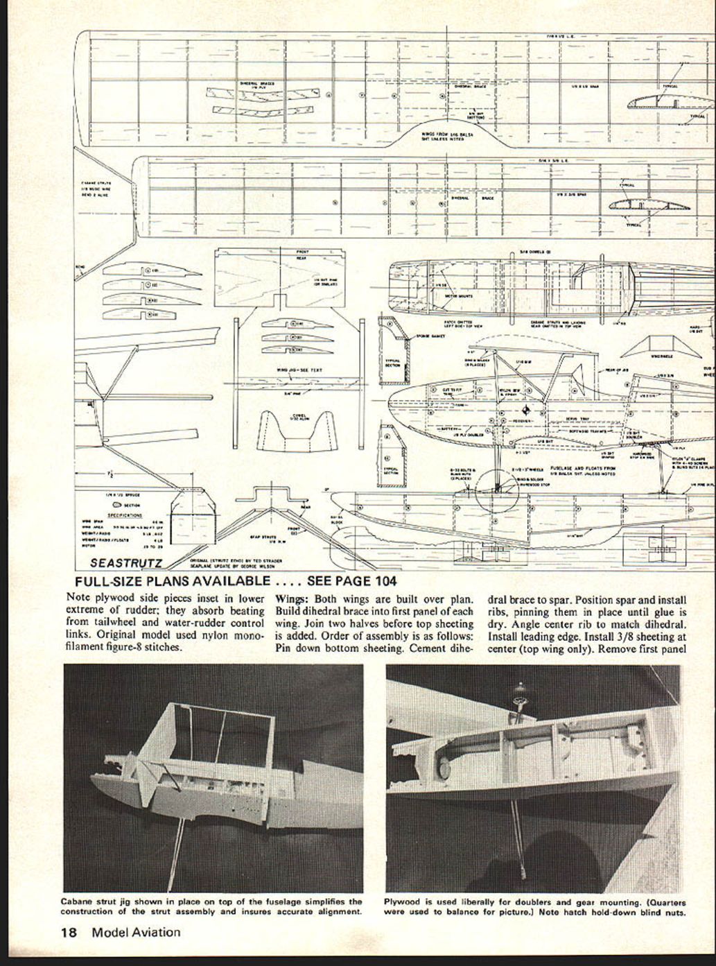
These parts (including the sub-rudder) are built from 3/16" sheet and strip. Use light, good-quality wood for minimum weight and anti-warping. Center member in stabilizer, and rear upright of sub-rudder, are medium hard for strength. Note plywood side pieces inset in lower extreme of rudder; they absorb beating from tailwheel and water-rudder control links. Original model used nylon monofilament figure-8 stitches.
Wings: Both wings are built over plan. Build dihedral brace into first panel of each wing. Join two halves before top sheeting is added. Order of assembly is as follows: Pin down bottom sheeting. Cement dihedral brace to spar. Position spar and install ribs, pinning them in place until glue is dry. Angle center rib to match dihedral. Install leading edge. Install 3/8 sheeting at center (top wing only). Remove first panel. from board and build it into second panel, using same order of assembly. First panel is blocked up to dihedral angle, while second panel is being built.
Washout is built into wings while top sheeting is being installed. Pin leading edge and center rib of one panel to building board. Block up rear wing tip by amount of washout shown on plan and pin in place. Block trailing edge up in two or three other places between tip and center, making it straight line center-to-tip. Install leading edge sheeting, center sheeting, and trailing edge sheeting. Amount of washout is not overly critical. Just make sure both sides have equal amounts of washout. Model is stable at slow speeds, and has no tendency to snap-roll.
Tip blocks are installed after they have been rough shaped. Trim and sand after they are in place.
Cabane Struts
Until cabane strut jig came to mind I was dubious about building a biplane. Vertical wooden struts used in many model designs solve the problem in a practical but not pretty manner.
Jig is built of most any material, but must be accurate. It provides places to rest tips of wing supports while they are being attached to struts. This is done with struts in position on fuselage, and jig resting atop the part of the fuselage normally under hatch.
First, build jig. Cement stops to center it on fuselage. These simplify positioning while you are building struts. Next, bend to approximate shape two U-shaped pieces of 1/8 music wire, and two 1/16 music wire tie struts. Cut two 1/8 m.w. wing supports to length. Using rubberbands and soft wire (#16 or 18 solid copper), mount wing supports in jig and fit U-shaped pieces to them. Re-bend as necessary to fit neatly in slot through fuselage, and for reasonable fit with wing support. When satisfied with fit, bind ends to wing supports, using thin copper wire, apply flux, and solder. Before you do second U strut, remove partially made assembly from jig, and slip piece of silicone rubber tubing over center part of wing supports. This makes soft, non-slip mount for wing. Push tubing as far as you can toward solder joints. Fit and attach second U-shaped piece. Tie struts are fitted, bound, fluxed, and soldered. Finished strut assembly slips off jig with little difficulty. Strut assembly is mounted to fuselage, using nylon monofilament line and epoxy. This produces well-aligned top wing mount.
Finishing
Insides of all structures are sealed with dope or thinned epoxy. (Hobbypoxy Formula 2, diluted 1-to-1 with thinner or 90% isopropyl alcohol, is good sealer.) Seal inside of pieces that are used to close the structure.
My model was finished using Silkspan over wood, except for float bottoms that were nylon covered. Open areas are covered with light Silkspan, then with nylon. Heat-shrink materials are not easy to waterproof.
Flying
Seastrutz didn't quite fly right off drawing-board. I planned an engine check and a bit of taxiing. Then Bob Martin and Bruce Selig made bids to test fly it. Weather was good, wind steady 10 mph. Takeoff required ten feet, climb-out was dramatic. Bob fed in full down trim and wished he had more. Except for too much climb and ballooning glide, first flight was a great success. Bruce verified Bob's findings. In its first two flights Seastrutz in its landplane configuration did most of rudder-elevator maneuvers that Bob and Bruce could think of, including inverted flight. They agreed that increased rudder area would be useful, and at least an 1/8 in. downtrim in stabilizer was necessary. Slow speed flight was steady with no unexpected snaps.
The next day Ed McCarty flew water tests. Wind was at least 20 mph with gusts. We found a place that was shielded by hills. Seastrutz steered well on water (a must if you are going to enjoy seaplane flying), got up on step with ease. Although the lake was deceptively calm, trees were blowing on the hill top. As usual, caution was thrown to the winds. We theorized that float drag would offset down-trim required for land flying, and set elevator trim to zero.
Takeoff was dramatic. After 75 feet with full throttle and some down-elevator, Ed pulled up and Seastrutz was off like a scared duck. In a full stall attitude at 50 feet, it hit wind blowing toward the hill and was blown end-over-end into the trees. Damage was minor. Test flying continued next week at the Fall Brimfield meet. By this time, stabilizer had a shim under its leading edge, and rudder area had been doubled. Seastrutz flew beautifully. Among its test pilots was Ted Strader's son Eric, who testified that it flew very much like its predecessor, the Strutz Echo.
If your Seastrutz is built with the incidences shown, it will perform very well. It is relatively docile. With its 46-in. wing span and compact biplane configuration, I felt it might be too quick for the average flier. This is not the case. It is not a difficult machine to fly from the land or water. Have fun!
Transcribed from original scans by AI. Minor OCR errors may remain.

