
THE SECRET
Leon Shulman
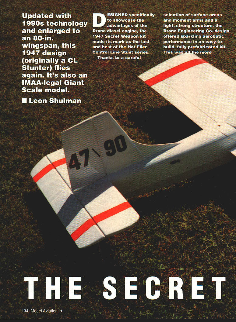
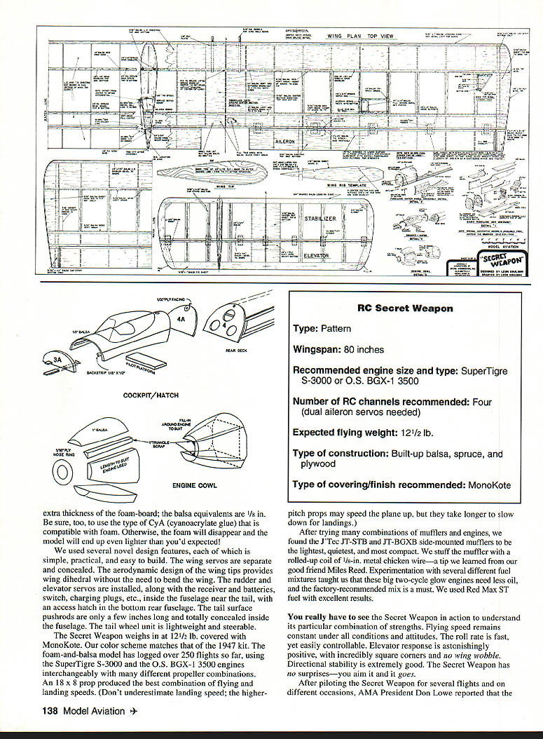
Updated with 1990s technology and enlarged to an 80-in. wingspan, this 1947 design (originally a CL Stunter) flies again. It's also an IMAA-legal Giant Scale model.
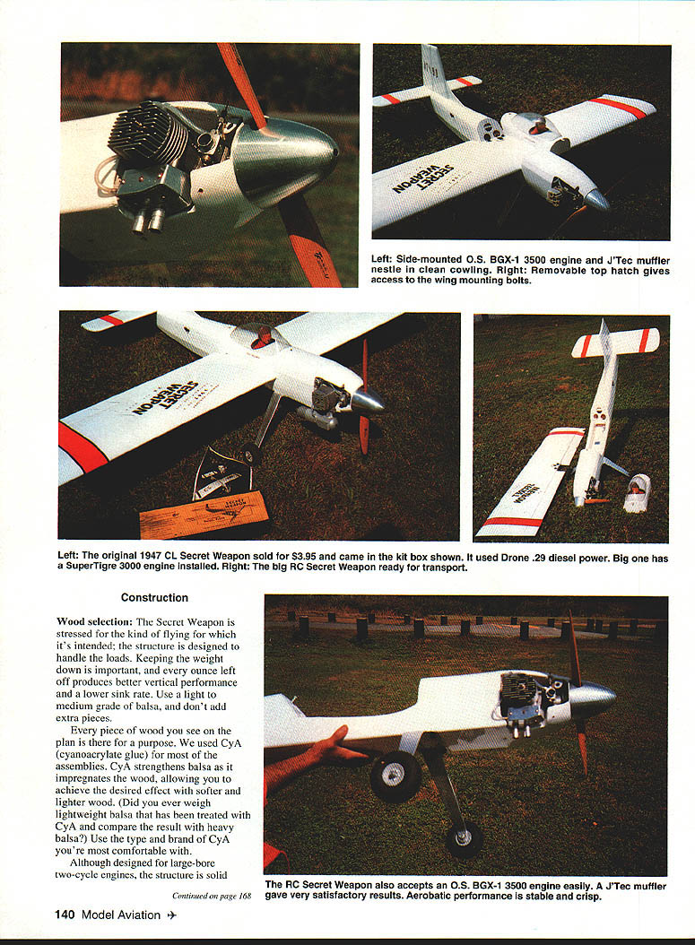
Designed specifically to showcase the advantages of the Drone diesel engine, the 1947 Secret Weapon kit made its mark as the last and best of the Hot Flier Control Line Stunt series. Thanks to a careful selection of surface areas and moment arms and a light, strong structure, the Drone Engineering Co. design offered sparkling aerobatic performance in an easy-to-build, fully prefabricated kit. This was all the more notable considering that Control Line was still in its infancy and designers had little to go on. Priced at $3.95 including covering material, the Secret Weapon won immediate success. Fans christened the model on its first flight: "The Secret Weapon! This bird really performs!" The name took, and Drone Engineering was quick to adopt it.
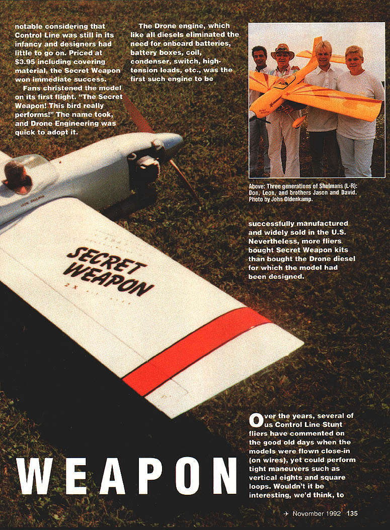
The Drone engine, which like all diesels eliminated the need for onboard batteries, battery boxes, coil, condenser, switch, high-tension leads, etc., was the first such engine to be successfully manufactured and widely sold in the U.S. Nevertheless, more fliers bought Secret Weapon kits than bought the Drone diesel for which the model had been designed.
Over the years, several of us Control Line Stunt fliers have commented on the good old days when the models were flown close-in (on wires) yet could perform tight maneuvers such as vertical eights and square loops. Wouldn't it be interesting to bring back a kit like the Dronette, the Hot Rock, or especially the Secret Weapon, in larger scale and with updated structural technology?
The push we needed came when one of our buddies gave us an original Secret Weapon kit with plans. After playing around with calculations for wing and power loadings based on the figures used in the original model, we determined that a twice-scale proportion looked feasible. The 80-in. wingspan and 1,200-sq.-in. wing area were just right for an IMAA-legal Giant Scale model. With luck, the larger model might perform even better than the 1940s version, especially without those flying wires hanging off the left wing.
Keeping the weight down was important. With their low weight-to-power ratios, the SuperTigre S-3000 and O.S. BGX-1 3500 engines both looked good. I already owned a SuperTigre S-3000, and we acquired one of the first O.S. BGX-1 3500 engines from our local hobby shop early in June 1990. So we had two different engines to try.
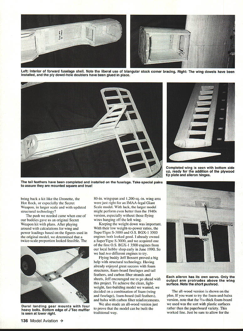
Flying buddy Jeff Bossert proved a big help with structural technology. Having already enjoyed great success with foam structures, foam-board fuselages and tail feathers, and carbon fiber strands and sheets, Jeff encouraged me to go ahead with this project. To achieve the clean, lightweight, fast-building model we wanted, we decided on a combination of foam (wing and fuselage), foam-board (tail feathers), and balsa with carbon fiber reinforcements.
We also made an all-wood version just to prove that the model can be built the traditional way. The all-wood version is shown on the plan. If you want to try the foam-and-balsa version, note that the 3/16-in. foam-board we used was the sort with plastic surfaces rather than the paperboard variety. This worked fine. Just be sure to allow for the extra thickness of foam-board compared to balsa equivalents.
Be sure to use the type of CyA (cyanoacrylate) glue compatible with foam. Otherwise the foam will dissolve and the model will end up lighter than you'd expected.
We used several novel design features that are simple, practical and easy to build. Wing servos are separate and concealed. An aerodynamic design of the wingtips provides the wing dihedral we needed without having to bend the wing. Rudder and elevator servos are installed along with the receiver, batteries, switch, charging plugs, etc., inside the fuselage near the tail-access hatch. Bottom-rear fuselage tail-surface pushrods, a few inches long, are totally concealed inside the fuselage. The tail-wheel unit is lightweight and steerable.
The Secret Weapon weighs 12-1/2 lb covered in MonoKote. The color scheme matches the 1947 kit. The foam-and-balsa model has logged over 250 flights so far using SuperTigre S-3000 and O.S. BGX-1 3500 engines interchangeably with different propeller combinations. An 18 x 8 prop produced the best combination of flying and landing speeds. Don't underestimate the landing speed; higher-pitch props may speed the plane up and make it take longer to slow down for landings.
After trying combinations of mufflers and engines, we found the J'Tec JT-STB and JT-BGXB side-mounted mufflers to be the lightest, quietest and most compact. The J'Tec muffler is a rolled-up coil of 1-5/8-in. metal chicken wire. One tip I learned from my good friend Miles Reed: experimentation with several different fuel mixtures taught us that the big two-cycle glow engines need less oil. In fact, the factory-recommended mix is a must. We used Red Max ST fuel with excellent results.
You really have to see the Secret Weapon in action to understand its particular combination of strengths. Flying speed remains constant under all conditions and attitudes. The roll rate is fast, yet easily controllable. Elevator response is astonishingly positive, with incredibly square corners and no wing wobble. Directional stability is extremely good. The Secret Weapon has no surprises—you aim it and it goes.
After piloting the Secret Weapon for several flights and on different occasions, AMA President Don Love reported the model can be flown directly ahead and close in and can do every conceivable vertical maneuver. The model is stable under all conditions and predictable in all flight maneuvers.
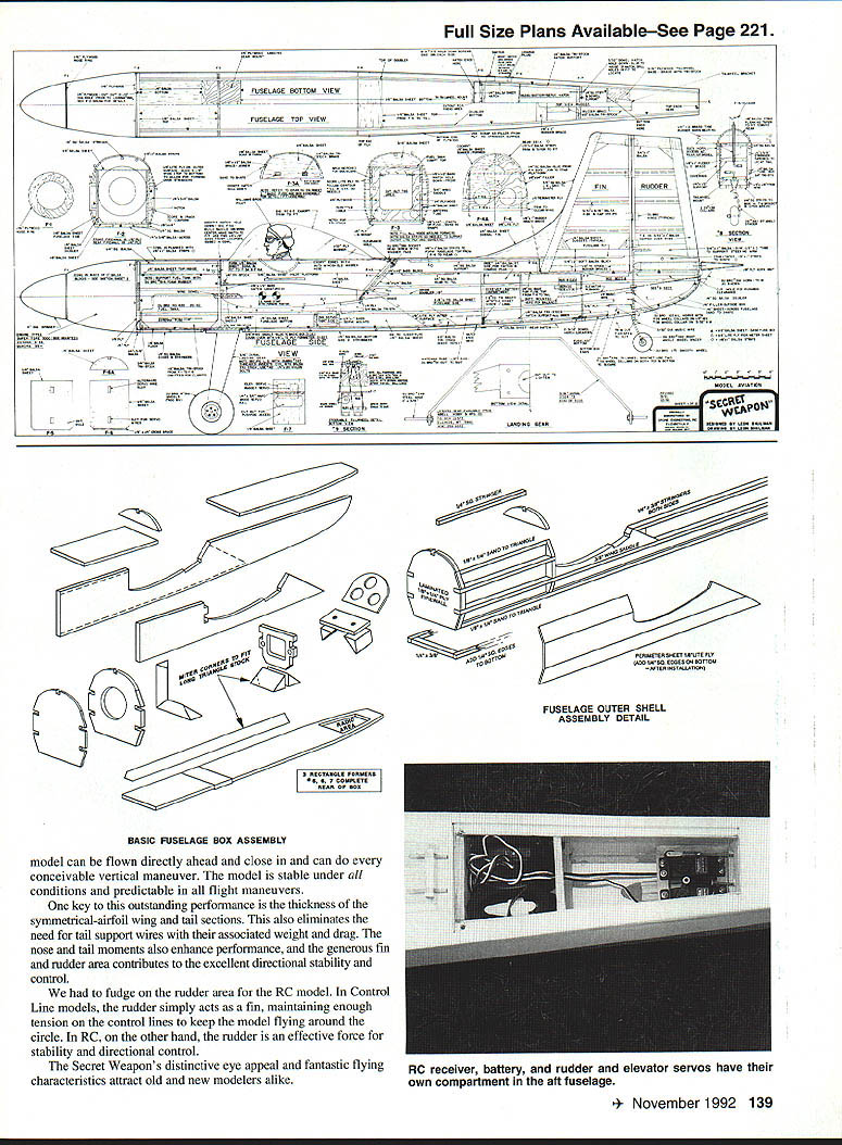
One key to this outstanding performance is the thickness of the symmetrical-airfoil wing and tail sections. This also eliminates the need for tail support wires with their associated weight and drag. The nose and tail moments also enhance performance, and the generous fin and rudder area contributes to the excellent directional stability and control.
We had to fudge on the rudder area for the RC model. In Control Line models, the rudder simply acts as a fin, maintaining enough tension on the control lines to keep the model flying around the circle. In RC, on the other hand, the rudder is an effective force for stability and directional control.
The Secret Weapon's distinctive eye appeal and fantastic flying characteristics attract old and new modelers alike.
BASIC FUSELAGE BOX ASSEMBLY
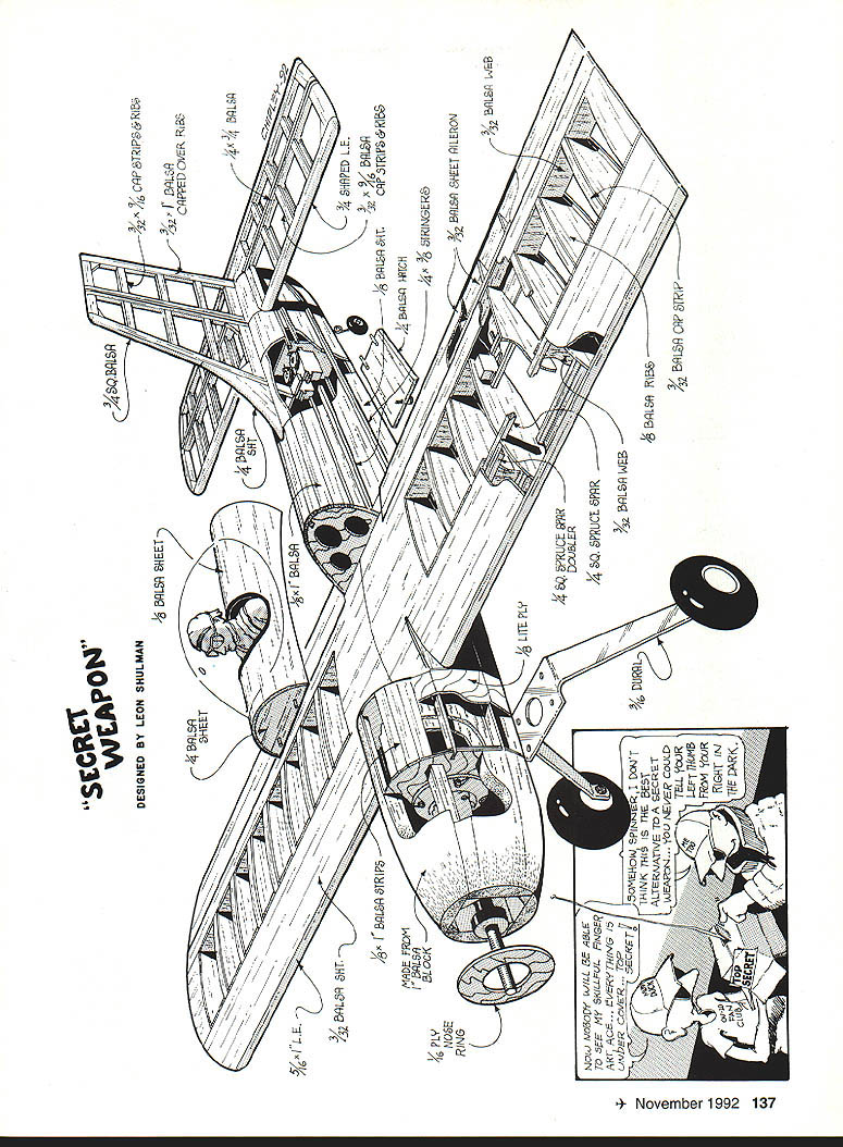
Model can be built either all-wood or with foam-and-balsa construction. Gather all the fuselage parts, and check them against the plan, photographs, and sketches to familiarize yourself with the assembly sequence. The unique structure of the fuselage permits its easy, trouble-free assembly and contributes to its lightness and strength. Don't deviate from the construction shown on the plan.
Attach the right and left doublers to the fuselage sides with slow-setting epoxy. Make certain you build a left side and a right side. Use weights to hold the assembly flat while the glue sets. Accurately mark the positions of formers 5, 6, and 7. Insert former 3 into the doubler notches. Taping or pinning the fuselage together evenly at the rear simplifies this initial assembly. Use a square to maintain alignment of the sides and formers.
Glue in formers 5 and 7. These must be located 1/8 in. from the top and bottom fuselage edges so that the fuselage top and bottom sheets fit flush with the outer edges. Fit and glue the long rear fuselage bottom sheet to these formers and to the fuselage sides; this forms the rear of the fuselage.
Glue the 1/4-in. ply landing gear mount to former 3. Make sure the inside surface of the mount is flush with the rear fuselage bottom, as shown on the plan. The mount will protrude temporarily 1/8 in. below the fuselage bottom sheet. Fit in the short sheet at the bottom front of the fuselage to complete this subassembly. The front part of this piece is square and in alignment with the fuselage sides.
Slide in the pieces of 1/2-in. soft triangle stock under former 3. Glue the triangle stock in place back to the rear of the fuselage doublers. Fit the pieces of 3/4-in. triangle stock against former 3 and the 1/4-in. landing gear mount to tie this high-stress area together. Fit the 1/2-in. triangle stock into the inside of the bottom hatch area between formers 5 and 7, then fit the pieces across to each former. This creates the radio-area hatch seat.
Fit former 6 in place. The location can vary according to the size of your receiver and battery pack. The location shown on the plan accommodates a seven-channel receiver and 800-mAh battery pack.
Sand the front part of the side and bottom sheeting square before installing former 2. Check that the bottom and side corners are square and that the former is properly aligned, then glue the former in place. Fit pieces of 3/4-in. triangle stock to the sides and bottom. Sheet the top of the rear, making certain the sheeting mates with all the formers and is flush with the fuselage top. This completes the fuselage box.
The 1/4-in. sheet fillers (two pieces) that form the fuselage tail section (at the lower rear of the structure) are glued to the outside of the fuselage box. Glue 1/4 x 1/4-in. balsa strips to each side at the top, continuing forward to former 4 (at the upper edge of the fuselage box). This creates the base for the balsa planking that forms the rear cowl (tail fairing).
Glue the 1/8 x 1/4-in. filler strips along the bottom edges of the fuselage box sides on the outside of the box. Sand the filler to a triangular shape and sand the fuselage bottom sheeting before installing former 2.
Attach lite-ply pieces with slow-setting CyA to complete the outer shell.
Mount the engine to the firewall, making sure the shaft is centered with 0° thrust. The engine mounting area is heavily reinforced, and the firewall is 1/4-in. plywood. The structure is solid enough for large-bore two-cycle engines and big four-stroke 4.5–5.5 cu. in. engines. It's even strong enough to handle a chain-saw engine, provided the engine is relatively small.
Use a die-cast engine radial mount if desired. A Du-Bro #420 (20-oz.) fuel tank provided plenty of flying time on our model. Line the fuel-tank compartment with foam rubber — Du-Bro #514, 1/2-in.-thick rubber pad stacked as necessary — and cut the pad to shape so that the tank floats in the compartment. Run fuel/vent lines through the firewall behind the engine radial mount, and drill holes in the mount to clear the lines to the carburetor and muffler. Fuel-proof the tank compartment and top cover before sealing the compartment.
Using 1/8-in. balsa, make a duplicate nose ring with a diameter of 4-1/4 in. Slide the ring over the drive washer and then over the original 1/16-in. ply nose ring. Mount the spinner backplate, propeller, hardware, and spinner assembly to the engine. Fit the cowl pieces to clear the muffler, carburetor, etc., and carve and sand the cowl to shape.
Make the fuselage top cowl later while fitting the wing. That way, you can drill through former 3 into the wing leading edge to locate the two dowels (see "Aligning and mounting the wing").
Complete the bottom of the fuselage by adding 1/4-in.-sq. strips as shown on the plan. Cut away a section to provide clearance for the landing gear.
Radio/servo installation and tailwheel assembly: mount the tail servos and radio gear as shown on the plan. You can use the radio to actuate the rudder servo to check linkage and operation. Make the rudder tiller arm and the tailwheel bracket platform. Mount the tailwheel bracket with a formed wire gear leg and install the tailwheel unit so it is steerable. Connect the tail wheel to its servo with a pushrod. We used Du-Bro #144 4-40 threaded rods for all servo pushrod connections, including those for the ailerons.
Always use keepers to secure the Kwik Links. Where applicable, use Du-Bro #497 4-40 swivel ball links on one end with a Du-Bro spring steel #304 Kwik Link clevis secured by a 4-40 nut at the other end. This is essential for all large models.
Tail assembly: The stabilizer and elevator, designed with torsional resistance to eliminate flutter, are easy to build. The 3/4-in. thickness of these parts increases the model's controllability and eliminates the need for tail wires and tail wire braces. The leading edge (LE) of the stabilizer is 3/4-in. I-beam stock.
Place the leading and trailing edge pieces on the plan; glue in the bottom center sheeting and all the bottom rib cap strips. Add the ribs, the top cap strips, and the top center sheeting. Add the soft balsa tip blocks.
Cut the elevator horn mount from 1/8 x 1-in. ply. Begin elevator assembly by positioning the front spar and the 3/32 x 1-in. rear trailing edge strips. Notch the bottom of the center section ribs to accept the plywood horn plate. Glue the long, triangular elevator ribs to the cap strips and to the leading and trailing edges. Glue in the top cap strips and the remaining trailing edge. Install the tip blocks, and add scrap balsa filler between the TE strips at the tips.
Sand the elevator to outline, and round off the tips. Taper the leading edge to allow for hinging and free movement. We used Du-Bro #257 heavy-duty hinges on all movable surfaces. The individual hinge pins were removed and replaced with a continuous length of .045 music wire running through all hinges.
Build the rudder and fin the same way you built the stabilizer and elevator. Use lightweight balsa throughout. Trial fit the stabilizer and vertical fin before mounting them to the rear of the fuselage. Check that the stab is horizontal and that the fin is vertical. Make sure the stab tips are equidistant from the nose; we pinned a string to the center of the nose cowl to check this measurement. Glue the stab with slow-setting CyA. Mount the vertical fin, making sure it's centered and in alignment. Glue in the triangle fin braces as shown on the plan.
Fit the rudder tiller into the fuselage from the bottom if necessary. The tiller rests against the leading edge of the stab. Trial fit the rudder after hinging to make sure everything works smoothly.
Mount the 1/4 x 1/2-in. brace for the rudder tiller; flow a drop of oil between the steel wire and the brass tubing for lubrication. Hook up the rudder tiller to the other side of the rudder servo arm as shown on the plan. Later cut the fuselage bottom for access to this assembly.
Make the radio access hatch from 1/4-in. balsa sheet. Mount the hatch as shown on the plan. Cover the remaining area of the fuselage bottom from the tail wheel rearward with 1/4-in. scrap balsa, then sand the area to a rounded contour.
Construction
Wood selection: The Secret Weapon is stressed for the kind of flying for which it's intended; the structure is designed to handle the loads. Keeping the weight down is important, and every ounce left off produces better vertical performance and a lower sink rate. Use a light to medium grade of balsa, and don't add extra pieces. Every piece of wood you see on the plan is there for a purpose.
We used CyA (cyanoacrylate) glue for most assemblies. CyA strengthens balsa as it impregnates the wood, allowing you to achieve the desired effect with softer and lighter woods. Use the type and brand of CyA you're most comfortable with, but be sure to use a foam-safe CyA if working with foam.
Although designed for large-bore two-cycle engines, the structure is solid enough for the big four-stroke 4.5–5.5 cu. in. engines being used today. Two different power plants were used on the RC models shown here: the SuperTigre S-3000 and the O.S. BGX-1 3500. Either one will do nicely, and we had no problem changing from one to the other.
Wing
The wing is structurally simple, using innovative wing tips rather than a conventional configuration to achieve dihedral. The spars are spruce, and double spars are used through the high-stress portion. The ribs are 3/32-in. sheet. Nine of the ribs are cut 1/8-in. deeper at the front spar notches (top and bottom) to accept the 1/8 x 1/4-in. spar doublers.
Splice the spars at the center, and glue the spar doublers to both the top and bottom spars; these become the front spars. Taper the ends of the doublers, if desired, as shown on the plan. Note that the ribs are made in one piece, then later are cut to accommodate the rear spar and the aileron leading edge.
Pre-cut the 1/4-in. balsa web that fits between the spars and ribs. These webs can be used as a spacer and extend from the center rib to the fourth rib on each side. Cut the 3/32-in. vertical webbing that fits between all the ribs on the front main spar. This webbing extends to the tip ribs, creating full-depth spars.
After all the ribs are in place with the 1/4-in. balsa web and the 1/8 x 1/4-in. spruce spar doublers, add the 1/8 x 3/32-in. balsa vertical webbing between the ribs and onto the spars as noted above. Glue the 1/8 x 7/8-in. beveled leading edge doubler to each rib. You can use two or three pieces to achieve the required length, splicing the wood as necessary and bracing it from the rear with scrap balsa. This doubled leading edge with its filling of glue adds tremendous strength, ensuring a securely attached, well-aligned LE sheeting. The excess sheeting at the front will be sanded away later to make room for the true leading edge.
Cut the ribs as shown on the plan. Glue the full-depth trailing edge spar to the rear of the ribs. Add the rib-to-rib sheeting and the tapered sheeting behind the spar. Glue blocks in the top and bottom sheeting to complete the wing.
Turn the wing over. Mark the locations for the hinge blocks. Glue the blocks to the trailing edge and to the inside of the top sheeting. Add the bottom sheeting to complete the wing.
Install the 3/32 x 4-in. LE sheeting. This is glued to the front spar and the 1/8 x 7/8-in. LE doubler as well as to each rib.
Slow-setting CyA works best for this task. Drill holes of approximately 1/8-in. diameter through every rib to the bottom bays. These holes ventilate the structure, keeping the covering and internal wood more stable throughout the life of the model. Fill the holes wherever near the longitudinal middle of each rib, and extend them to the tip. Cut holes in the center section ribs to feed the servo wires and "Y" connector through the center.
Turn the wing over, and finish sheeting the leading edge and center section out to the third rib on each side. Install the true leading edge. This should be spliced at the center.
Ailerons: You'll have some aileron ribs left over from building the wing center section. These can be used as doublers at the wing tips, if needed for final fitting. Lay the 3/32 x 3-in. top sheeting flat, and install the aileron ribs as shown on the plan. Glue the tapered TE stock against the ribs and aileron sheeting, trimming the stock if necessary for easy assembly. Assemble the second aileron the same way.
Glue in hinge blocks to mate with those in the wing section. Install the 1/8-in. ply aileron horn base, cutting away some of the lower surface of the aileron to embed the base securely. Sand across the ribs and the rear of the aileron sheeting to create a smooth surface for installing the 3/32 x 3-in. bottom sheeting.
Finishing wing assembly: Sand the leading edge to shape. Install the tip ribs and the wing tip web. This ties the spars together and creates the angled wing tip plate. Install the cap strips and the 1/8-in. Lite Ply angled wing tip. The wing tip is deliberately cut oversize for easy alignment, then trimmed to final shape. Sand the wing surfaces with 3/32 balsa sheeting as shown on the plan.
Install the aileron hinges. We used Du-Bro #457 heavy-duty nylon hinges, with a length of .045 music wire as a continuous hinge pin. Sharpen one end of the wire, and bend the outer 1/4 in. at about a 90° angle. This tab will be glued in place to secure the hinge pin. Check the alignment carefully.
Sand the wing and ailerons to matching contour. Thread the hinges for each wing half on the .045 wire. Working with one wing half at a time, make sure everything fits together and operates smoothly before epoxying the hinges in place. Check again for smooth operation, then set the assembly aside to cure. Use Du-Bro's Kwick Hinges (#537 or #538) to simplify this job.
When the epoxy has fully cured, build the box for mounting the aileron servos. We used 1/4 x 3/8-in. bass or spruce for the simple box shown in the wing plan detail. To preserve the neat, aerodynamically clean design, make sure that only the output arm protrudes above the wing surface. Later, the servo will be covered over. Because of the box configuration, however, the covering can be cut away for servo access, then reinstalled for concealment.
Thread the servo wires to a "Y" connector. We tape our connectors together and secure the loose wires against the rear spars with a drop of silicone glue between each rib; this keeps the wires from flopping around. The servo connector goes out the top of the center section. Later, the connector will be plugged into the aileron extension from the receiver. For now, tie thread to the aileron connector and bury the wires in the wing center section until the next step has been completed.
Reinforce the center section with glass cloth. We used very light glass cloth, which worked well applied with either CyA or epoxy resin. Be sure all surfaces are sanded smooth before applying the fiberglass. Apply the glass cloth to the aileron horn area as well for additional strength. Sand the fiberglass with fine paper when it is thoroughly dry.
Screw the aileron horns in place, and fashion the servo rods as shown on the plan. Set the servo arm for the indicated aileron deflection. When your Secret Weapon rolls on its axis, you'll see why we use more up aileron deflection than down—usually 20° up and 10° down.
Connect the aileron servos to the receiver. Power up the RC system and center the ailerons. After the aileron servos are centered, the system can be turned off.
Make the wing tip block, and install it against the Lite Ply tip. Trim and sand the block to match the aileron. This wing tip is designed to prevent aileron flutter. If you're using a side-mounted engine, add approximately three ounces of weight to the left outboard wing tip to counterbalance the engine cylinder so you can still do smooth maneuvers.
Aligning and mounting the wing
Fit the wing into its saddle. Check vertical alignment by sighting the wing from above. We used string with a T-pin to verify that a specific point on each wing tip was equidistant from the tail. Check horizontal alignment by sighting the wing from the front.
When the wing is centered, drill a pilot hole for each wing dowel. These are drilled through the holes in former 3 and into the leading edge. Remove the wing from the saddle. Using a square for good alignment, drill 5/16-in. holes in the front spars. Taper the dowels in the front spars (we used a pencil sharpener so that it's easier to center them inside the wing).
Fit the wing into the saddle again. File or elongate the pilot holes in former 3 as necessary to accept the dowels. When you're satisfied, glue a 1/4-in. ply gusset against the front of former 3 to compensate for any earlier misalignment of the dowels.
Complete the top nose cowl assembly and secure the fuel tank compartment. Measure and drill holes for the rear wing bolts. We used Du-Bro threaded inserts (#395) and Du-Bro #42 nylon wing bolts. The Du-Bro threaded inserts were also used to secure the aluminum landing gear.
Cockpit and hatch
Refer to the construction shown on the plan. Using 1/8-in. balsa, build a platform base for the hatch on the wing center section. Build the hatch itself from 1/8 x 6-in. balsa. Mold the wood by soaking it in water, wrapping it around formers 3A and 4A, and leaving the assembly overnight.
Assembling the hatch is simple. Taper a 1/8 x 1/2-in. strip to brace the 1/4-in. sheet against the 1/8-in. balsa. Glue two pieces of 1/8 x 1-in. basswood into the slots in 3A, bracing them on the inside with 1/4-in. triangle stock as shown on the plan. This anchors the hatch front in former 3. Use CyA for all installation. Secure the hatch at the rear with a Du-Bro #386 socket-head sheet metal screw.
Trim the hatch, and sand it to conform with the shape of the wing and fuselage. Finally, install a pilot and canopy. Any respectable builder/flyer includes a pilot in his best-performing model!
Decorating the model
The featured model was finished with MonoKote and star-shaped graphics. A complete set of these graphics is available from Custom R/C Graphics (telephone: [212] 324-7858).
I hope this updated vintage Stunter satisfies those of you who have requested such a revival over the years. The RC Secret Weapon represents 43 years of fun and pleasure ('47–'90). And with all the fun we're having, we're set for another 43 years!
Suppliers of Parts and Materials
- Jim Jones, 36631 Ledgestone Drive, Mt. Clemens, MI 48043
- Micro-X Products, P.O. Box 1063, Lorain, OH 44055
- Indoor Model Supply, Box 5311, Salem, OR 97304
- Sig Manufacturing Co., Inc., Montezuma, IA 50171
- Ray Harlan, 15 Happy Hollow Road, Wayland, MA 01778
- Wayne Trien, 7408 West Hanna Ave., Tampa, FL 33615
If you have any questions concerning construction or adjustment of pieces, my address is 5669 Victoryview Lane, Cincinnati, OH 45233. Please include a self-addressed and stamped envelope.
I would like to thank all of the people who have helped me over the years—too many to list, but you all know who you are. Also, all the people who graciously give of their time at the contests.
Secret Weapon/Shulman (plan-specific notes)
Shape to conform to the fuselage outline; study the plan renderings of formers 2 and 3 for detail. The bottom strip ends at the 1/4-in. tail section filler; the 1/8 x 1/4-in. filler will blend with the tail-section filler when the assembly has been completed. This area will be sanded and tapered to flow with the 3/8-in. stringers, forming an oval section at the tail.
Install the 1/4 x 3/8-in. stringers between formers 2 and 3, the associated triangle-stock pieces, and the 1/8 x 1/4-in. filler pieces (see the plan). Add the remaining 1/4 x 3/8-in. stringers to each side, from former 4 to the tail. Splice all stringers as necessary to run full-length; vary the splice joints so that they are not opposite each other for greater strength.
Glue the 3/8-in. wing saddles adjacent to the associated stringers on the fuselage sides. Glue the wing-saddle bolt mount with 3/4-in. balsa triangle stock.
If you wish, use 1/8-in. sheet balsa as the perimeter sheeting. Fit the perimeter sheeting to the fuselage sides and stringers and to the 1/8 x 1/4-in. triangle stock on the wing. Use hot-melt adhesive or foam-safe CyA. Be sure not to use solvent-based cements which will dissolve the foam.
Attach the Lite Ply pieces with slow-setting CyA to complete the outer shell. Run fuel/vent lines and fuel-proof the tank compartment as described earlier.
Engine cowl and fuselage top: make one side of the cowl to fit the nose rings for the necessary spinner clearance. Use CyA for fast assembly. Complete the cowl structure by cutting and fitting the remaining pieces as shown, to clear the muffler, carburetor, etc. Carve and sand the cowl to shape.
Radio/servo installation, landing gear, aileron linkage, hinge details, and all other assembly specifics are shown on the plan and described in the Construction and Wing sections. Use keepers and proper hardware (as detailed earlier) for reliable control-system connections.
Leon Shulman and the Model Airplane Hobby
Leon Shulman was bitten by the aviation bug while walking home one afternoon in Brooklyn, New York, in the early 1920s. He saw a huge, block-long shadow cast on the ground by the airship Graf Zeppelin flying overhead. He was fascinated by its immense size and ability to carry so many people from afar while remaining aloft for long periods of time.
The box tops from three boxes of Cracker Jack and a dime sent through the mail brought him his first kit—a stick-and-tissue ROG (rise-off-ground) rubber-power model. Assembling with muslin and thread, this first attempt at making something that would fly had mediocre results—but it was challenging. There followed a series of scale models both nonflying and flying. But he craved a bigger model with a real gasoline engine. These were Depression years, however, and money was too tight.
Determination won out. As a teenager Leon joined and worked in the CCC (Civilian Conservation Corps), earning enough money to buy a Brown Jr. engine. The engine flew for the first time in October 1936—with a 50-ft. string tied to the tail skid of the model! Leon ran behind it as it took off. If everything wasn't looking good, he would slow down and tighten up the string, causing the model to settle back to the ground.
As a designer he built a T-D Coupe in 1937 from magazine plans and redesigned it to suit his tastes. Not having the money to buy light fabrics for covering, he covered the model with brown wrapping paper and painted it with Red Devil bicycle enamel! The model was flown for many months.
His next design was the Sky-Scraper, and it featured innovations like single-wheel landing gear and a wing made from 1/4-in. sheet balsa with a modified McBride B-7 airfoil. One experimental design, the 9G, had mixed merits: a very thin, undercambered airfoil and an experimental tail. Many flights went well—but if the engine quit during a steep climb the model would stall and perform an uncontrollable dive, hence its name.
Leon's first widely accepted models were the free-flight designs Wedgy (1940), Zomby (1941), Banshee, and Zoomer (1946).
A season of military service began in 1943. Leon had been studying aeronautical engineering at the Casey Jones School of Aeronautics during 1939–42 when WWII broke out. He was accepted into the U.S. Army Air Corps as an aviation cadet in March 1943 and was always a class leader in becoming a solo pilot in all categories throughout his pilot training. He was commissioned a second lieutenant in December 1943 and went on to fly the Martin B-26 Marauder and the Consolidated B-24 Liberator. He eventually qualified to fly more than 20 different warplanes. Much of his active duty experience was spent in towing targets for aerial gunnery practice and ferrying B-24s around the 1st Air Force to replace bombers going to the front lines in Europe. He was also designated as a Check Pilot and still holds an active rating as a Commercial Pilot, Multi-Engine Land.
His career as a manufacturer began when he heard about the diesel concept in 1946 and knew that it would be very reliable since it required no batteries, coil, points, or magneto. With encouragement and financing from a close friend, Leon began manufacturing the Drone engine. Over 20,000 examples of two models of the Drone were sold before the advent of the glow plug made its impact on the model engine market. Leon's company also developed a line of props, fuel, engine accessories, and kits to complement the Drone.
Leon made the first RC electric model car in 1959—20 years ahead of the time it burst into popularity.
His early club associations began when he first joined The Airplane Model Builders Exchange (TAMBE) club. When it fell apart, he was one of the early members of the Brooklyn Skyscrapers club, which is still in existence today. In 1936 he was one of the early members (#52) of the International Gas Model Airplane Association (IGMAA). In November 1939 he was named as an official delegate (representing the New York area model clubs) to the National Model Aircraft Conference held at Langley Field, Virginia. This conference created the Free Flight rules which have formed the basis for subsequent free-flight rule making.
Leon was a very active competitor in Free Flight during 1939–1941. His service in WWII temporarily halted his modeling activity. Afterward, he became active in Control Line competition, then turned to RC in 1951. He competed in Pattern and Scale until retiring from the contest circuit in the mid-'70s.
As a businessman, Leon began working for a hobby wholesaler in the New York/New Jersey area after his efforts with the Drone diesel. He was at one time sales manager and VP of Monogram Models in Chicago. He then decided that his interests were better served by working with several different manufacturers having diverse products. He has been a manufacturer's sales representative since 1955 and is also a hobby consultant who works at product development and marketing for many companies.
Leadership in the hobby
Leon has a fascinating background as a contest director. His first big meet was the Eastern States Model Airplane Championships sponsored by the S. Kresge Department Store. In 1946 the New York Daily Mirror chose Leon as the contest director of the famed Motor Meet on Long Island. Shortly afterward, the Plymouth Motor Corp. began sponsoring a series of model meets all over the country culminating in a final championship meet in Detroit—the famous Plymouth International. Leon was chosen to be CD of several regional meets and several big finals in Detroit. He also was CD at several AMA Nationals into the 1950s.
His "Shulman System" of RC contest management (frequency pins/frequency cards/flight-line assignment/etc.) faced its biggest test at one Eastern States RC contest, when 122 RC fliers were accommodated. Today's widely used RC contest management system evolved from Leon's earlier solution.
Cherished leadership honors include induction into the AMA Hall of Fame in 1978 and the National Free Flight Hall of Fame in 1982.
Current interests and activities
Leon's most recent interest has been Giant Scale models.
Two of his 11 grandchildren have taken to the RC hobby and have started onto the contest circuit. David, age 14, and Jason, age 16, have already become respected competitors in the RC Pattern events.
Leon's interest in model aviation has never waned, and he is looking forward to another 70 years of designing, redesigning, building, and flying model airplanes and of associating with similarly addicted persons (model airplane enthusiasts).
Transcribed from original scans by AI. Minor OCR errors may remain.

