
Serendipity
Jerry Nolin
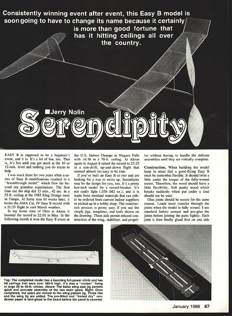
Consistently winning event after event, this Easy B model is soon going to have to change its name because it certainly is more than good fortune that has it hitting ceilings all over the country.
EASY B is supposed to be a beginner's event, and it is. It's a lot of fun, too — that is, it's fun until you get stuck at the 10- or 12-mm level and nothing you do seems to help. I was stuck there for two years until a series of Easy B modifications resulted in a "breakthrough model" which flew far beyond my grandest expectations. The first time out the ship did 15 mm, 42 sec, 55-ft. ceiling at the 1985 King Orange meet in Tampa. At Santa Ana 10 weeks later, it broke the AMA Cat. IV Easy B record with a 21:23 flight in cool March weather.
In my home state of Ohio at Akron it boosted the record to 22:01 in May. The following month it won the Easy B event at the U.S. Indoor Champs at Niagara Falls with 16:36 in a 70-ft. ceiling. At Akron again in August it raised the record to 23:25 in a non-drift, up-and-down flight that seemed almost too easy to be true.
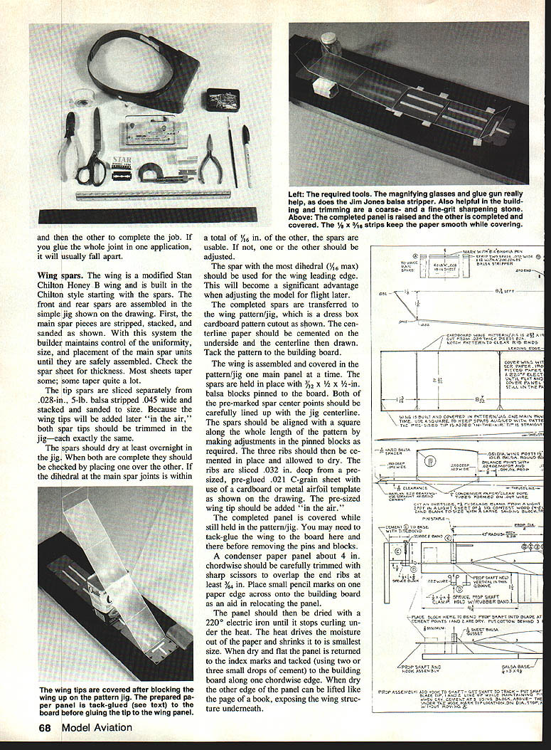
If you've built an Easy B or two and are looking for a way to move up, Serendipity may be the design for you, too. It's a pretty low-tech model for a record-breaker. It's not really light (0.038–0.042 oz.), and it is made from standard materials that can be ordered from current indoor suppliers or picked up in a hobby shop. The construction process is straightforward if you use the simple jigs, templates, and tools shown on the drawing. These aids permit relaxed construction of the wing, stabilizer, and propeller without having to handle delicate assemblies until they are virtually complete.
Construction
A good-flying Easy B must be somewhat flexible. It should twist a little under the torque of the fully-wound motor. Therefore use wood with a little flexibility; avoid soft, punky wood that breaks suddenly under load.
Glue joints should be secure because loads must transfer through the joints when the model is fully wound. I use standard indoor cement and pre-glue joints before joining the parts lightly. Each joint is then finally glued first on one side and then the other. If you glue the whole joint in one application it will usually fall apart.
Wing spars
The wing is a modified Stan Chilton Honey B wing and is built Chilton-style, starting with the front and rear spars assembled in a simple jig.
- Strip, stack, and sand the main spar pieces as shown on the drawing. This maintains control of uniformity, size, and placement until the spars are assembled.
- Check the spar sheet for thickness — most sheets taper to some degree.
- Tip spars are sliced separately from 0.028-in., 5-lb. balsa, stripped 0.045 in. wide, stacked, and sanded to size. Because wing tips are added later "in the air," trim both spar tips exactly the same in the jig.
- Allow the spars to dry in the jig at least overnight. When both are complete, place one over the other. If the dihedral at the main spar joints differs by more than a total of 1/16 in., adjust one spar. Use the spar with the most dihedral (up to 1/16 in. max) for the wing leading edge — this will help when adjusting the model for flight later.
Transfer the completed spars to the wing pattern/jig (a dress-box cardboard pattern cutout). Cement centerline paper to the underside and draw the centerline. Tack the pattern to the building board.
Assemble and cover one main panel at a time while the structure is still held in the pattern/jig:
- Hold spars in place with 3/8 x 1/2 x 1/2-in. balsa blocks pinned to the board and line up pre-marked spar center points with the jig centerline.
- Align spars square along the whole length of the pattern, making adjustments in pinned blocks as required.
- Cement three ribs in place and allow to dry. Ribs are sliced 0.032 in. deep from a precut, pre-glued 0.021-in. C-grain sheet using a cardboard or metal airfoil template.
- Add the pre-sized wing tip "in the air."
Cover the completed panel while still in the pattern/jig. You may need to tack-glue the wing to the board before removing pins and blocks.
Covering procedure (condenser paper):
- Trim a condenser paper panel about 4 in. chordwise; it should overlap the end ribs at least 3/16 in. Place small pencil index marks from one paper edge across onto the building board to aid relocation.
- Dry the panel with a 220°F electric iron until it stops curling; the heat drives moisture out and shrinks the paper.
- Return the panel to the index marks and tack one chordwise edge to the board with two or three small drops of cement.
- Lift the other edge like the page of a book to expose the wing structure. Place small drops of clear dope every 3/8 in. along the near spar. Lower the paper and gently press down; a balsa strip weight can help.
- After the dope dries, lift the paper again and place dope drops along the ribs, then lower the paper.
- Lift slightly to place dope drops along the remaining spar and lower for final drying.
- When dope is dry, trim the paper at the leading and trailing edges even with the spar edges using a new double-edge razor blade.
- Remove the partially completed panel from the pattern/jig and repeat for the second panel.
- To cover wing tips, block up the wing at the proper angle and use the same “book page” method with pre-primed paper. Tack seams at dihedral joints with small drops of condenser paper cement.
Stabilizer
- The stabilizer and its jig are designed to permit a little dihedral to aid covering with one piece of paper.
- Build the stabilizer flat. Outlines are 0.032 in. wide, stripped from a 0.022-in. sheet of 5½ to 6-lb. balsa.
- Wet strips, pull them around the form shown on the drawing, and hold with silkspan strips. Bake 10 minutes in a 200°F oven. The resulting bows should be over-bent and will require opening to install in the jig.
- Construct the rest of the stabilizer like the wing. The overlap at the rear spar makes it stronger than the front; with the reversed airfoil this helps resist diving out after a rafter bump.
- When covering, place a 1/8 to 3/16-in. strip at the wedge point shown. Cut a condenser paper piece about 1½ in. wider than the frame all around. Dry it with a 220°F iron until flat and smooth. Tack it to the stabilizer tips with small drops of clear dope, then tack to the front spar.
- The jig’s many small notches allow dope to be placed on the outline without sticking the whole frame to the jig. Finish by tacking the paper to the trailing edge, trim the outline with a new razor blade, gently ease the stabilizer out of the jig, and finish cementing the paper down using condenser paper cement applied with a fine brush.
Fin
- Make the fin from a bow formed on the stabilizer bow form.
- The easiest covering method is in a small jig similar to the right end of the stabilizer jig. Cover the fin in the jig on the left side; it will hold its shape once covered.
Motor stick
- Use 4- to 6-lb. Sig Contest Wood; select the lightest 1/8-in. C-grain stock you can find. Hold to a light and pick a spot with light streaks at least 1/4 in. wide.
- Cut an oversize motor stick from a light spot, about 7/8 in. wide and 9/16 in. long. It will spring, bend, and twist when cut out, so start oversize.
- Gradually trim to size with a large sanding block covered with 150–180-grit paper. Sight down the length to see whether it needs sanding to get straight and measure with micrometers. Do final sanding with fine sanders.
- Trim the stick to 9/64 in. long. It should be straight, with edges left square for now.
Rear hook and gusset:
- Bend the rear hook from 0.015-in. piano wire. Smooth the end on a sharpening stone before bending. Copy the hook shape on the drawing closely.
- Pierce the stick for the hook with a sharp-ended 0.015 wire. Force a little Ambroid cement into the hole and insert the cement-covered hook at the correct angle. It should line up from the rear.
- When dry, add the oversize gusset shown on the drawing as firm support for the hook. Trim and add a final light coat of Ambroid.
Front bearing and spacer:
- I recommend the Harlan EZB bearing. To get the required 3/32 in. shaft clearance, mount it on a 1/4-in. hard balsa spacer.
- Glue an oversize spacer to the front of the stick with undiluted Ambroid. When dry trim flush with the front and sides of the stick.
- True the Harlan bearing of edge burrs with a fine file and roughen the mating side with #400 sandpaper. Glue the bearing to the spacer with Ambroid. When dry, align by holding up to a light bulb and sighting through the bearing holes from the back of the stick. A small balsa aiming point can be attached to the hook to help set the proper thrust line.
- When dry, trim the stick to conform to the drawing. Reglue the bearing with a thin coat of Ambroid, ensuring the entire base of the bearing is encased in cement. No other fastening is required.
Boom and propeller spar:
- Strip the boom small end first to 0.075 in. width from a Micro-X tapered sheet using a Jim Jones balsa stripper. Bring down to size with a large block and fine sandpaper. Trim to 12-3/4 in. and sand smooth.
- Don't save weight by making the boom floppy. A floppy boom undoes the advantages of a good, stiff, long boom.
- Make the round propeller spar from 3/32-in. sq. balsa stripped from a 6½-lb. sheet. Hold strip to bright light to determine grain. Cut first edge parallel to grain with a steel rule as guide. Strip off a few 1/32-in. sq. blanks and trim corners with a razor to make them roughly octagonal.
- Round spar blanks (three or four at a time) using the large sanding blocks, sanding with a rolling motion until round and 0.067 in. diameter. This takes practice and patience.
- Put the taper on by sanding one end at a time; tips should be brought down to 0.030 in. diameter.
- Cement spars together in the jig using Ambroid thickened with Ambroid dry. Locate spars on the jig using its centerline and clamp with binder clips or pins until dry. Glue the tip spars on last.
After the spar assembly is dry, transfer to the wing pattern/jig and apply the leading and trailing edges. Wing ribs are 0.032-in. deep, pre-sized, pre-glued 0.021-in. C-grain sheet; use the airfoil template. Add pre-sized wing tip after panel completion. Cover while still held on the pattern/jig and tack as required before removing pins and blocks.
Wing covering (summarized)
- Trim paper to overlap end ribs at least 1/8 in. Place pencil index marks to aid relocation.
- Dry with a 220°F iron until it stops curling.
- Tack one edge, apply clear dope to spars and ribs as needed, lower paper gradually and press down, then trim at edges with a fresh razor.
Prop blades
- The 30° grain angle in the prop blade material permits much thinner blades and is key to making large, lightweight props. Use 0.009-in. C-grain-cut balsa sheet usually used for tail boom tubes on big models.
- For lower ceilings use 3/32- to 1/8-lb. stock; for high ceilings (Akron) use 3/16- to 5/32-lb. stock.
- Make both blade blanks from the same 1/8 x 18-in. sheet. Join sheet edges with regular indoor cement and lightly sand blanks.
- Make a prop blade template from dress-box material and maintain the 30° alignment while cutting blades. Lightly sand blade edges to about 0.007 in. Put spar and blade-tip locator marks on the back side.
Forming the blades:
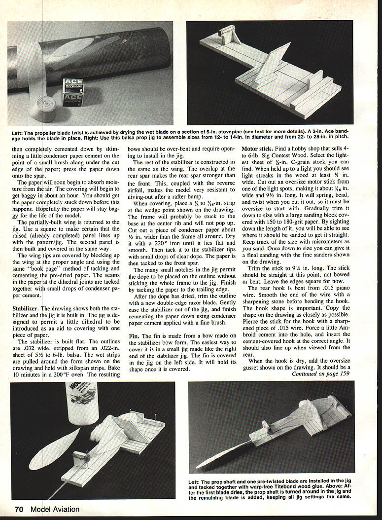
- Put the required twist in wet blades using a 5-in. stovepipe or can as a form. Lay out the 16° line on paper and wrap around the can; permanently mark the 16° line on the can.
Suggested starting props:
- 14 in. diameter, 28-in. pitch used on record flights (a large prop to start with).
- 13 x 26 or 14 x 26 will do over 20 min. in a 150-ft. ceiling even in cool weather.
- 13 x 23 is a good starting prop: 17–18 min. in a 150-ft. ceiling.
- 12 x 24 is the “trouble” prop — like low gear, useful when stuck.
Be prepared to build a variety of props. They're easy to make but you may need a few tries before you're satisfied.
Prop assembly jig and procedure
- The prop assembly jig is required to attach formed blades to the formed shaft and hook assembly. Make the jig from 1/8-in. and 1/16-in. sheet balsa. The jig is typically reversed for indoor prop work to provide access to the underside of the blade during assembly.
- Key points during assembly:
- Ensure the prop hook is properly installed in the clamping fixture.
- Ensure the blade tip is against the centerline of the diameter stop.
- Ensure the blade is against the selected 45° station.
- Ensure the balsa shaft lines up with both the premarked center point and the tip of the blade.
- Clock the shaft height and fore-and-aft location of the 45° station until everything lines up.
- Place a small drop of Titebond wood glue at the shaft tip and let it dry (don't try to glue the whole shaft at once). Then cement the inboard end of the blade and let it dry.
- Because the shaft is straight and the blade centerline is curved, force the shaft against the blade and cement using the block shown on the drawing. Apply small drops of Titebond every ~1/4 in. to "stitch" the formed blade to the shaft along both sides.
- After the first blade has dried completely, remove the assembly from the jig, turn it around, and cement the other blade using the same settings. A poor attempt can be soaked off and retried.
Use Titebond because it does not shrink or warp. Expect to build several props to find the best one for your situation.
Assembly
- Fasten and brace the fin to the tail boom as shown; use Titebond to avoid warps later. Use condenser paper cement to stick paper to the boom.
- Cement the boom to the motor stick with straight Ambroid. Lay the assembly flat on the board and shim up to match the motor stick. Lightly pre-glue both parts. The resultant stick should be perfectly straight along the upper side.
- Cement the stabilizer to the boom with small drops of Titebond, preferably over a simple plan view to keep everything straight. Keep the motor stick vertical with small square blocks.
- Make the wing slider and trim to equal the weight of the completed wing and separate wing posts. Install the prop weight and motor on the motor stick together with the wing slider. Move the slider fore or aft until the stick balances 1 5/8 in. behind the sill. Lightly mark the left side of the motor stick at both ends of the slider — these are the locations for the paper tubes that form the wing attachment points.
- Slide the wing posts to the bottom of the 1/4-in.-long paper tubes. Cement the tubes (with posts) to the stick at the pre-marked locations using Titebond. Posts should be perpendicular to the stick and square — and parallel to each other in the front view. Lightly sand the stick at one mounting point if required to get everything straight.
- When the tubes are dry, lightly notch both posts as shown on the drawing (without removing them from the tubes). Remove the rear post and cement it to the rear spar with the 3/16-in. offset shown. Set the motor stick to the required incidence and hold while the cement dries. Then cement the front post and check alignment.
Final adjustments and flight tuning
- By carefully sanding the stick between the wing posts toward an elliptical shape you can gradually increase full-power wing twist and eventually eliminate crabbing/stalling. After each sanding the ship will accept a little more torque until it will take full winds and climb strongly.
- Sand a little at the front and rear of the stick as shown on the drawing. The extra downthrust bend on the tail will help keep flying speed up, minimizing required wing twist.
- When fully wound the tail is often tilted slightly wrong (right side high), causing a larger full-power circle. Offset this with downthrust, stick bend, and tail bend. Eventually additional left stabilizer tilt may be the only solution.
- The model offsets torque partly through left wing “flare”: at steep full-power climb the center of lift is closer to the leading edge and the left leading edge bends upward, causing flare that helps balance torque. The amount of flare depends on the strength and taper of the left front spar: a sharp taper causes flare near the tip (undesirable); a less tapered spar, weaker near the center, will flare evenly over the half-span and provide good torque control without making the right wing stall. These flaring characteristics are built into the spar dimensions, but additional left wing flare can be obtained by reducing spar depth near the left front wing post with successive light sanding.
Rubber motor
- I have used old Pirelli Wakefield motors, stripped with a rotary rubber cutter. Check among Free Flight friends for this rubber; if you can't find it you'll need to use current U.S.-made indoor rubber.
- Under low ceilings (where most Easy Bs are flown), U.S.-made rubber can be useful because of its flatter torque curve. Low-ceiling motors should be shorter and wider than high-ceiling motors.
- Level flight should almost be achieved on the last full four or five winds. Back the motor off 30–40% until the model barely climbs.
Maintenance and development
A completed Easy B is never truly finished. After flying it, anything that is not right can be corrected by softening the offending part with water or solvent, removing it, and replacing it with something better. Fly the model, tune it for the best performance you can get, then build a better model. Structural integrity and aerodynamic harmony are every bit as important as low weight.
Finally, the high-ceiling secret of this design is its ability to climb to ~180 ft on the full burst of a long, thin motor and then spin off nearly all of the winds on a slow, open letdown. Under Category II and III ceilings it can fly with the prop running at about 85 rpm on a very low rubber weight.
Suppliers
- Sig Manufacturing Co., Inc., Montezuma, IA 50171
- Ray Harlan, 3 Happy Hollow Rd., Wayland, MA 01778
- Micro-X-Products, P.O. Box 1063, Lorain, OH 44052
- Indoor Model Supply, Box C, Garberville, CA 95440
- Jim Jones, 36631 Ledgestone Dr., Mt. Clemens, MI 48043
- Franklin Chemical Industries, Columbus, OH 43207
Transcribed from original scans by AI. Minor OCR errors may remain.

