


Servo Cycler
Bob Kopski
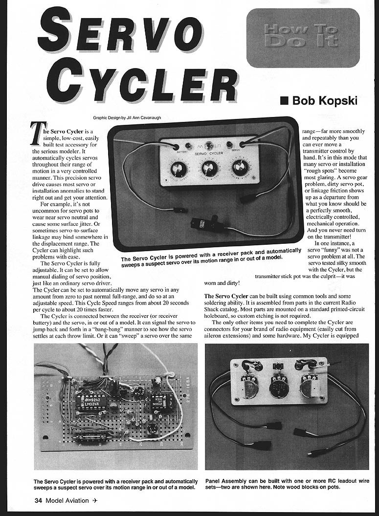
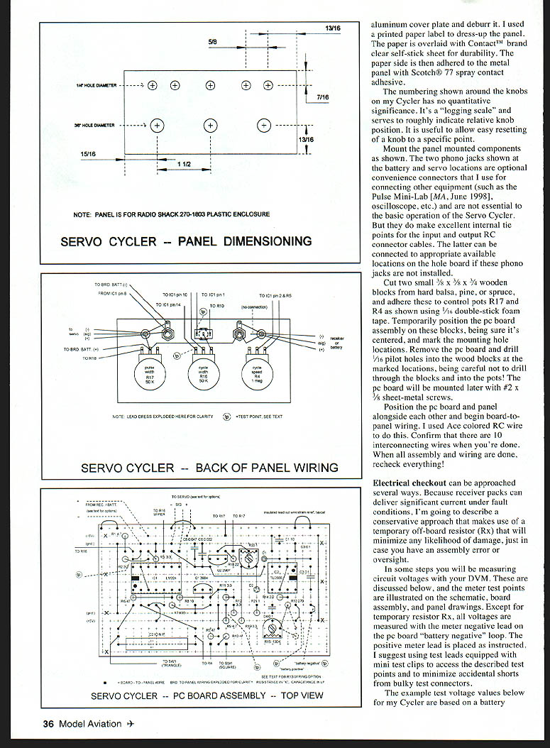
The Servo Cycler is a simple, low-cost, easily built test accessory for the serious modeler. It automatically cycles servos throughout their range of motion in a very controlled manner. This precision servo drive causes most servo or installation anomalies to stand right out and get your attention.
For example, it's not uncommon for servo pots to wear near servo neutral and cause some surface jitter. Or sometimes servo-to-surface linkage may bind somewhere in the displacement range. The Cycler can highlight such problems with ease.
The Servo Cycler is fully adjustable. It can be set to allow manual dialing of servo position, just like an ordinary servo driver. The Cycler can be set to automatically move any servo any amount from zero to past normal full-range, and do so at an adjustable speed. Cycle Speed ranges from about 20 seconds per cycle to about 20 times faster.
The Cycler is connected between the receiver (or receiver battery) and the servo, in or out of a model. It can signal the servo to jump back and forth in a "bang-bang" manner to see how the servo settles at each throw limit. Or it can "sweep" a servo over the same range — far more smoothly and repeatably than you can ever move a transmitter control by hand. It's in this mode that many servo or installation "rough spots" become most glaring. A servo gear problem, dirty servo pot, or linkage friction shows up as a departure from what you know should be a perfectly smooth, electrically controlled, mechanical operation. And you never need turn on the transmitter!
In one instance, a servo "funny" was not a servo problem at all. The servo tested silky smooth with the Cycler, but the transmitter stick pot was the culprit — it was worn and dirty!
The Servo Cycler can be built using common tools and some soldering ability. It is assembled from parts in the current Radio Shack catalog. Most parts are mounted on a standard printed-circuit holeboard, so custom etching is not required.
The only other items you need to complete the Cycler are connectors for your brand of radio equipment (easily cut from aileron extensions) and some hardware. My Cycler is equipped with two input and output connector sets, to fit all my installations. Checkout and calibration requires only a known good working servo and a digital volt meter (DVM).
How Does It Work?
Operation of the Cycler is best understood with a look at the schematic. Much of the circuitry is based on quad operational amplifier IC1. Quad section IC1a is connected as an active divider which establishes an internal bias voltage that in part controls certain internal signal swing limits.
Sections IC1b, IC1c, and transistor Q1 are wired as a function generator that makes two waveforms. One is a triangle signal appearing on IC1 pin 1. The other is a square wave appearing on Q1 collector. The common frequency of these waveforms is adjustable by Cycle Speed control R4 — from very slow to quite fast. The triangle waveform is used to move the servo smoothly over the range, while the square wave is the "bang-bang" drive waveform. The choice is made with switch SW1.
The actual control pulse that signals the servo is developed by current pump Q2 and frame-rate generator IC2, operating in conjunction with the function generator waveforms. IC2 is an astable asymmetric multivibrator designed to clock at about 40 to 50 Hz — the normal RC transmitter frame rate range. The noncritical frame rate is set with trimmer R15.
IC2 output waveform is a 200-microsecond negative-going pulse appearing at pin 3. This pulse dumps any charge that may be on capacitors C5/C6. When IC2 pin 3 is "high" (most of the time), the capacitor pair is free to charge in a linear ramp manner from current supplied by Q2. The charge buildup continues until Q2 saturates. The capacitor voltage then rests at this level until reset by IC2 via D1. This occurs at the frame rate.
This repetitive ramp signal is applied to IC1d along with the chosen waveform (triangle or square) from the function generator circuit. IC1d functions as a comparator and develops a positive-going output when pin 10 is higher in voltage than pin 9. Specifically, the two applied waveforms are designed to have this polarity condition during an "overlap" range of about 0.6 ms to about 2.4 ms. This overlap time is time-variant and produces a changing output control pulse width on IC1d pin 8 that is applied to the servo under test.
What this all comes down to is a servo drive signal that looks and acts just as if you were "banging" a transmitter stick back and forth or alternatively moving the stick slowly and smoothly over some range. The difference is that the Cycler does this in a fully adjustable, controlled, smooth, and repeatable manner — much more so than can be done manually with a transmitter stick.
The Cycle Width control (R16) adjusts the amount of servo motion. When fully counterclockwise, no sweep signal is output and the servo sees a pulse width set by the Pulse Width control R17 (manual servo driver control). Cycling operation is obtained by advancing R16, which causes servo motion on both sides of the manually set position. Full sweep capability actually exceeds normal servo motion. The triangle/square wave choice can be switched at any time, and Cycle Speed (R4) can be varied at any time as well.
Servo Cycler - Parts List
Semiconductors
- IC1 LM324 Quad Operational Amp — 276-1711
- IC2 TLC555 CMOS Timer — 276-1718
- Q1 MPS3904 NPN Transistor — 276-2016
- Q2 MPS2907 PNP Transistor — 276-2023
- D1, D2 1N4148 Switching Diode — 276-1122
Capacitors
- C1 10 µF 35V Radial Aluminum — 272-1025
- C2 10 µF Non-Polarized Electrolytic — 272-992
- C3 0.1 µF 50V Mylar — 272-1069
- C4 0.1 µF Monolithic — 272-109?
- C5 0.047 µF Mylar — 272-1068
- C6 0.022 µF 50V Mylar — 272-1066
Fixed Resistors
(all are 1/4 watt carbon film)
- R1, R9 4.7K — 271-1330
- R2, R3, R11 4.7K — 271-1328
- R12, R19 3.3K — 271-1328
- R5, R6, R10 47K — 271-1325
- R7 100K — 271-1347
- R8 10K — 271-1343
- R13 (NOTE*) 270K — RSU11345337
- R14 2.2K — 271-1325
- R18 22K — 271-1339
- R21 1K — 271-1321
- Rx 100 ohms, temporary — 271-1311
(*) NOTE: You can make 270K by wiring 220K (271-1350) and 47K (271-1342) in series — see option illustrated on PC board assembly drawing.
Variable Resistors
- R4 1M Linear Taper Variable — 271-211
- R15 100K Trimmer — 271-284
- R16, R17 50K Linear Taper Variable — 271-1716
- R20 1K Trimmer — 271-280
Switches, Connectors, and Sockets
- SW1 SPDT Toggle — 275-625
- 2 Phono Jacks (optional) — 274-346
- 1 8-Pin IC DIP Socket — 276-1995
- 1 14-Pin IC DIP Socket — 276-1999
Miscellaneous / Mechanical
- Project Box — 270-1803
- Universal PC Board — 276-168
- Assortment, ACE R/C Colored Wire — 276-168
- 24 Gauge Wire, tinned — 278-1341
- 3 Knobs — 274-415
- 2 #2 × 3/8" sheet metal screws — 64-3025
- 2 1/4" grommets
- Wood blocks, double-stick foam tape — see text
- RC system aileron extension / connector set A/R
- Panel labeling as desired
The example test voltage values below for my Cycler are based on a battery measuring 4.8 volts. Batteries that differ from this exact value are OK, but corresponding test values will be in proportion to the actual battery voltage used.
Assembly
Prepare the PC board
- Cut the PC board to size.
- Study the photos/drawings (count holes!) and drill two 3/32" mounting holes in the locations pictured.
- Cut the printed conductors at the marked X locations.
- Install the wire jumpers as shown in the Jumpers drawing. All jumper wires are #24 or #26 bare tinned copper wire, except three insulated wires that serve as leadout wire strain reliefs. Two active jumpers are shaped as half-loops (battery negative and battery positive) for test use during checkout.
- Some holeboard holes accommodate two wires. Two jumpers are located under forthcoming IC sockets; solder these after the sockets are in place (next). There should be 27 wires on the board after this step — please confirm before proceeding.
Install components
- Install the IC sockets with the identifier notches located as shown to help avoid IC installation errors. (ICs will be installed later.)
- Install the trim pots next, followed by the two transistors. Be sure to orient the transistors correctly.
- Install the capacitors, noting that C1 is polarized.
- Install diodes D1 and D2. D1 is shown cathode-up, while D2 is installed cathode-down. The black band on diodes marks the cathode terminal.
- Complete the assembly with resistor installation. (Board-to-panel wires will be installed later.)
Inspect and clean
- Inspect your work, tidying any imperfect solder joints and clearing any solder bridges. Use a lens to aid in this task.
- Clean the solder side of the assembly with a solvent such as acetone and a small brush. Minimize solvent on the component side, blow/blot dry, and set the assembly aside.
Panel and enclosure
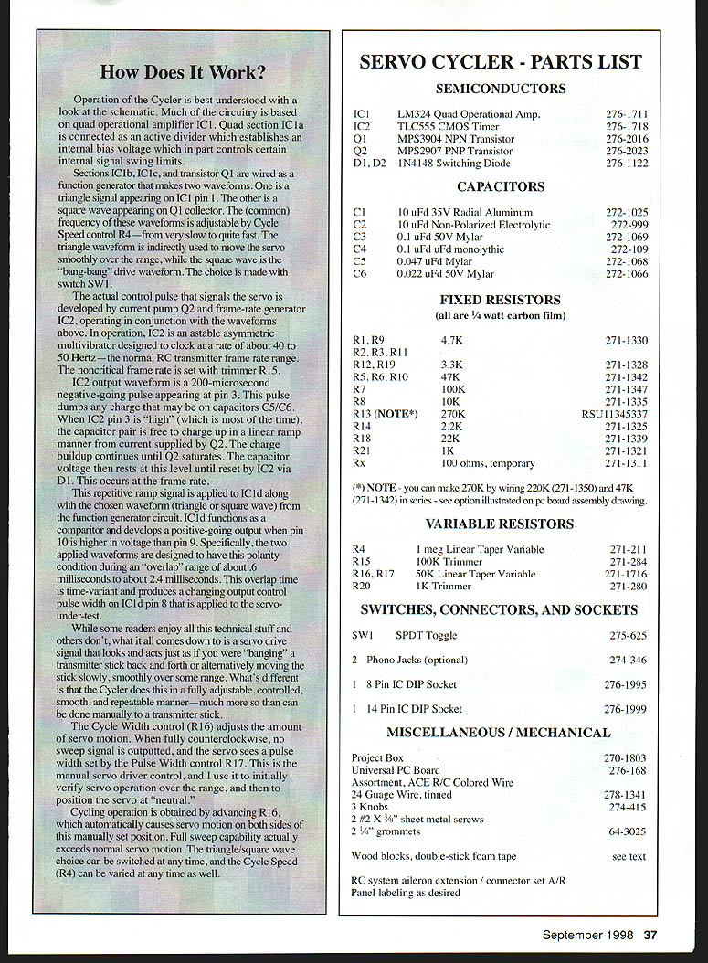
- Mark and drill the hole pattern in the panel and the aluminum cover plate, and deburr it.
- Dress up the panel with a printed paper label overlaid with a clear self-stick sheet for durability. Adhere the paper to the metal panel with Scotch® 77 spray contact adhesive.
- The numbering shown around the knobs on my Cycler has no quantitative significance — it's a "logging scale" to roughly indicate relative knob position and allow easy resetting.
- Mount the panel-mounted components as shown.
- The two phono jacks shown at the battery and servo locations are optional convenience connectors (for the Pulse Mini-Lab, oscilloscope, etc.) and are not essential to basic operation. They do make excellent internal tie points for input and output RC connector cables. If phono jacks are not installed, connect the RC connector cables to appropriate locations on the hole board.
Mechanical mounting
- Cut two small 3/8 × 5/8 × 3/4" wooden blocks from hard balsa, pine, or spruce and adhere to control pots R17 and R4 using 1/16" double-stick foam tape.
- Temporarily position the PC board on these blocks, center it, and mark mounting hole locations.
- Remove the PC board and drill 1/16" pilot holes into the wood blocks at the marked locations — be careful not to drill through the blocks into the pots.
- The PC board will be mounted later with #2 × 3/8" sheet-metal screws.
- Position the PC board and panel alongside each other and begin board-to-panel wiring. I used ACE colored RC wire. Confirm that there are 10 interconnecting wires when done.
- When all assembly and wiring are done, recheck everything.
Electrical Checkout
Because receiver packs can deliver significant current under fault conditions, use a conservative off-board resistor (Rx) that will minimize any likelihood of damage during checkout.
- Temporarily wire a 100 ohm, 1/4 watt carbon resistor (Rx) in series with the receiver battery positive lead. This can be done with a temporary adapter cord using modified aileron extensions or by soldering the temporary resistor in series with the (+) wire to the PC board.
- Begin checkout by setting:
- Cycle Speed (R4) fully counterclockwise (CCW)
- Cycle Width (R16) fully CCW
- Pulse Width (R17) about midrange
- SW1 to the "triangle" position
- Trimmers R15 and R20 about midrange
- With no ICs installed in their sockets, set your DVM/DMM to the 2 (or 3) volt range and connect it across the 100 ohm resistor. Polarity does not matter. Then connect your 4.8 volt receiver battery.
- You should read about 0.18 volts across the resistor, indicating a normal static current draw of about 1.8 mA. Do not proceed beyond any step that does not produce the correct result.
- Disconnect the battery and install IC2 correctly oriented. Reconnect power; the meter should now read about 10% higher. If OK, connect the DVM negative lead to the PC board battery negative test loop and the positive lead to the battery positive test loop. Note the reading.
- Connect the meter positive to IC1 pin 14 (best accessed at Cycle Width control R16). This voltage should be about 0.29 times the measured battery voltage. A reading within ±5% is OK.
- Move DVM positive to the collector of Q1 (the top wire of R9 is convenient) and read about twice the pin 14 value. If OK, disconnect the battery, install IC1, reconnect power, reconnect your DVM across test resistor Rx, and observe about 0.23 to 0.34 volts. In this condition the circuit is operating.
- Connect a servo to the OUTPUT jack. Set Cycle Width R16 near midrange so the servo is approximately at neutral. Slowly increase Cycle Speed until the servo sweeps smoothly over its range. If the servo jumps back and forth ("bang-bang") or chatters, reduce Cycle Width or Cycle Speed as required.
- Adjust trimmers R15 and R20 to center the sweep about the servo's neutral position and set desired end points.
Reconnect the DVM leads to the PC board with DVM positive to IC1b pin 1 (most accessible near SW1). With battery connected you should see the DVM tracking a slowly, smoothly varying voltage from about 0.8 V to about 2.0 V. Move the DVM positive back to Q1 collector (R9 wire) and watch the reading alternate at a slow rate between 0 and about 2.8 V. If you do not get these results, carefully recheck your assembly. When all above is OK, disconnect the battery and remove the temporary 100 ohm resistor; you're done with it.
Calibration and Use
Centering the Pulse Width control (R17)
Radio Shack pots' electrical rotation does not line up exactly with mechanical rotation, so find the electrical center of R17:
- Temporarily disconnect the wire(s) from one of the two used pot terminals.
- Measure total resistance (outside terminal to outside terminal) with your DMM on Ohms.
- Example: if R17 reads 46.9K, divide by two (~23.5K).
- Connect your ohmmeter from one outside terminal to the center (wiper) terminal, and rotate the pot shaft for the calculated value. The pot is now in electrical center.
- Without moving the shaft, loosen and adjust the knob pointer to center it (indicating "neutral").
- Resolder the loosened pot wire and mount the PC board assembly on the panel.
Transfer standard calibration
- Select a known good servo and use your radio system to establish its neutral output arm position (use aileron or elevator channel; stick and trims centered).
- Connect the servo to the Cycler output lead and connect the battery.
- With the Pulse Width knob positioned as centered above, adjust trimmer R20 if necessary to bring the servo arm to its established neutral position.
- Move the Pulse Width control knob over the range and observe corresponding servo movement. The available range should exceed full stick and trim travel on the transmitter.
- Reset the PW control knob to mid position (servo neutral).
- Adjust the Cycle Width knob clockwise about halfway and observe a slow, smooth sweep of the servo about the set position.
- Switch SW1 to the square-wave side and observe the stepped ("bang-bang") movement. Be patient — it may take a few seconds for the function generator to lock onto steady operation.
- If the servo chatters when the cycle is fast, reduce Cycle Speed or Cycle Width as required.
When properly adjusted, the Servo Cycler will sweep a suspect servo smoothly and repeatedly, making installation anomalies, worn gears, dirty pots, or linkage friction easy to detect and correct.
Cautions and Notes
- The Cycler is capable of about one back-and-forth cycle per second. This is very fast and can drive servos into conditions worse than stall, causing high current, overheating, and amplifier failure. Do not operate any servo for more than a few seconds at the highest sweep speed. Lower rate cycling (as with normal transmitter stick motion) is of no concern.
- Trimmer R15 can be set more precisely to your exact transmitter frame rate if desired. This is not critical for servos, but can be important with certain electronic speed controls (ESCs).
- R20 can be set more carefully for a more symmetrical PW control range if high precision is desired.
- The Servo Cycler will work perfectly with four- or five-cell receiver packs. It will work below about 4.5 volts, but at that point your battery should be charged anyway.
- R13 can be made up of two resistors as shown on the assembly drawing and parts list to avoid stocking one particular value.
- The recommended Radio Shack plastic box has internal bosses on the base. If you have interference fit with these, drill them off with a 3/8" bit, taking care not to go through the box bottom.
- If you have various radio brands you can install more than one set of input and output leads, or use Deans connectors with adaptors for different servo connector types.
- Aside from observing anomalous servo arm behavior, you can also listen for servo sound "funnies" by holding a servo to your ear while the Cycler is smoothly sweeping it.
I have used my Cycler on eight different servo brands/model types and some ESCs as well, and all work just fine. I hope you find the Cycler useful. I welcome any questions or comments about its design or application. Please enclose an SASE with any correspondence for which you'd like a reply.
Bob Kopski 25 West End Dr. Lansdale, PA 19446
Transcribed from original scans by AI. Minor OCR errors may remain.

