
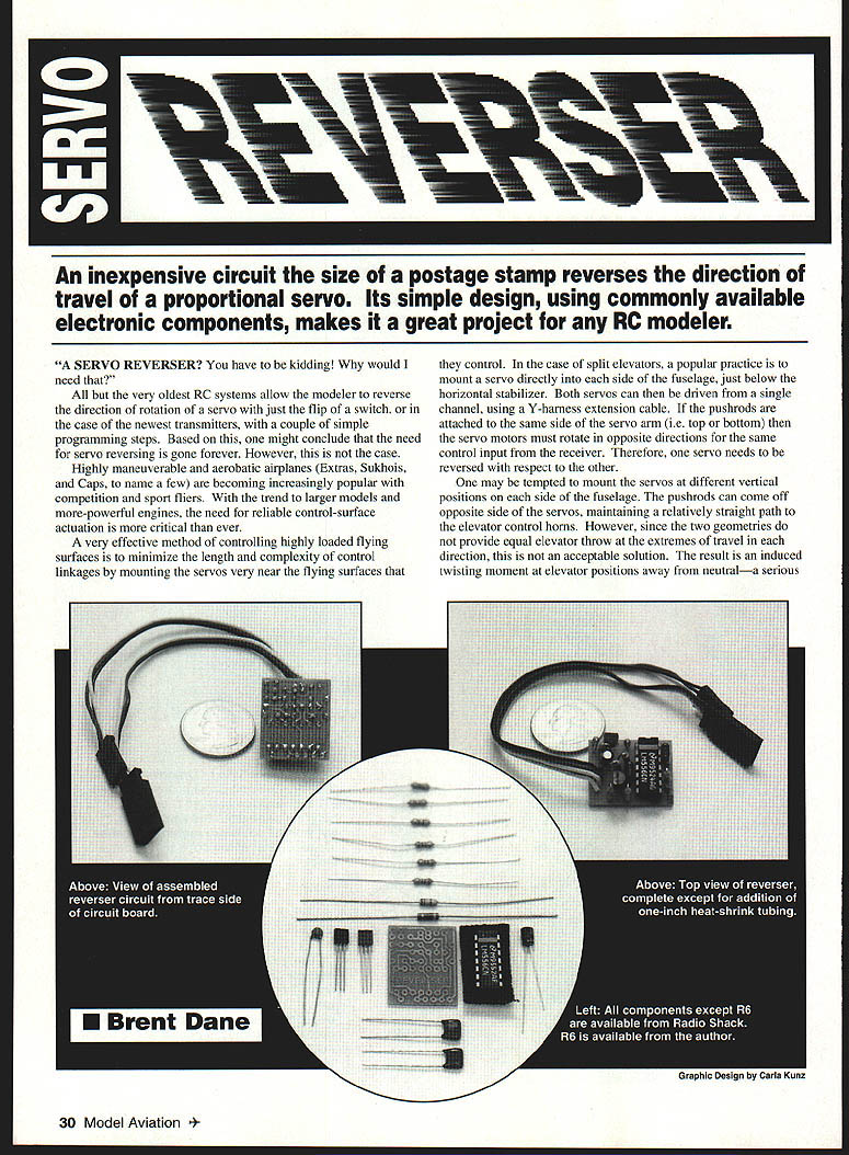
Servo Reverser
An inexpensive circuit the size of a postage stamp reverses the direction of travel of a proportional servo. Its simple design, using commonly available electronic components, makes it a great project for any RC modeler.
All but the very oldest RC systems allow the modeler to reverse the direction of rotation of a servo with just the flip of a switch or a few programming steps. However, there are still many situations where an inline servo reverser is useful.
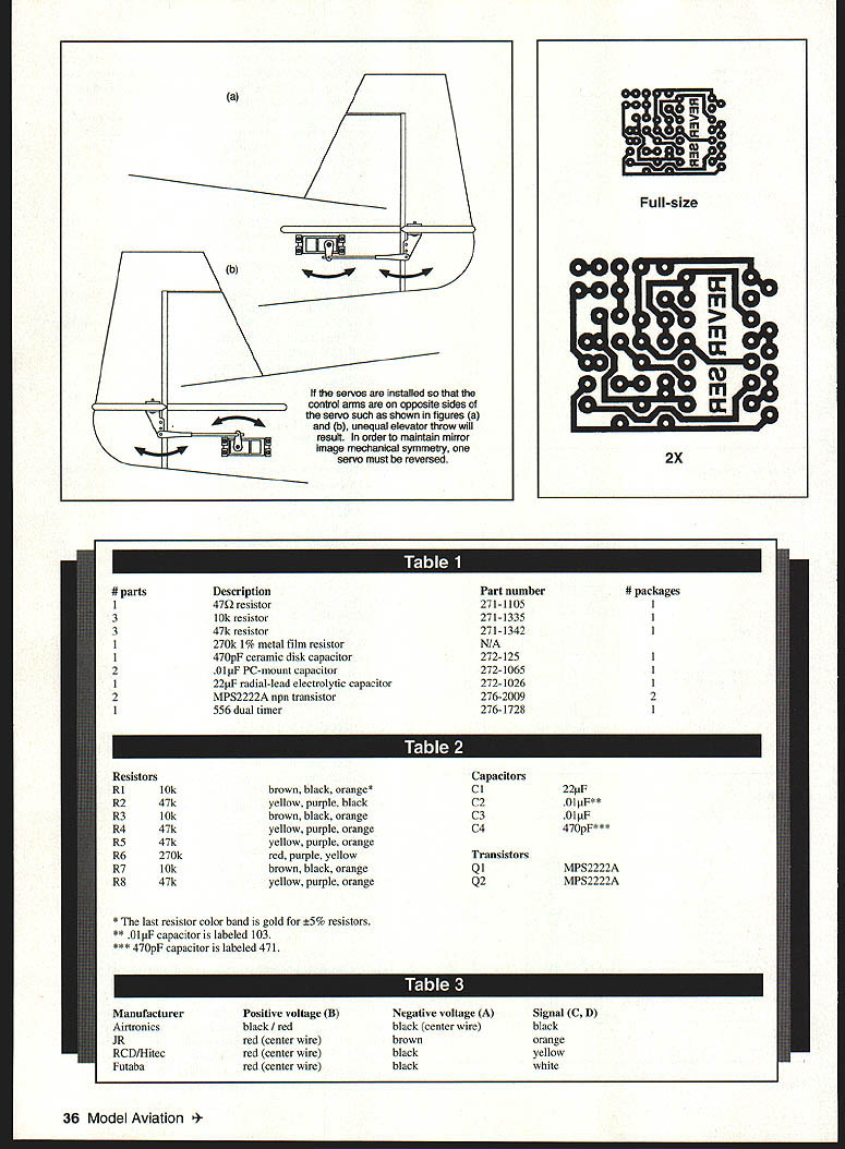
Highly maneuverable and aerobatic airplanes (Extras, Sukhois, Caps, and similar designs) benefit from mounting servos close to the control surfaces to minimize pushrod length and complexity. For split elevators, a common practice is to mount a servo directly in each side of the fuselage and drive both from a single receiver channel using a Y-harness. If the pushrods are attached to the same side of each servo arm (top or bottom), the two servos must rotate in opposite directions for the same control input. One servo therefore needs to be reversed relative to the other.
Mounting servos at different vertical positions so that pushrods exit opposite sides preserves straight pushrods but generally produces unequal elevator throw extremes and induces twisting moments away from neutral—undesirable on roll-sensitive aerobatic models. A better approach is to maintain mirror-image geometry and force one servo to rotate opposite the other by inserting an inline electronic reverser between the Y-harness and the servo.
There are several ways to reverse a servo:
- Physically modify the servo (reverse motor and potentiometer wiring). This is often difficult or impractical.
- Use separate radio channels and electronic mixing. Many transmitters do not pass trim changes to the slave servo, making this unreliable.
- Insert an electronic device between the Y-harness and the servos to intercept and convert the control pulses. This is the approach used here.
A common shortcoming of some commercial reversers is an onboard centering trim pot (carbon-film) that drifts with temperature. The design presented here avoids that problem by using a fixed 270 kΩ 1% metal-film resistor for centering, providing good temperature stability.
Theory of Operation
A standard servo has three wires to the receiver:
- V+ (positive battery voltage)
- V− (ground)
- Signal (pulse train)
The signal line carries positive pulses at about 60 Hz. Pulse widths vary between about 1.0 ms and 2.0 ms:
- 1.0 ms → one mechanical limit
- 2.0 ms → the opposite limit
- ~1.5 ms → center
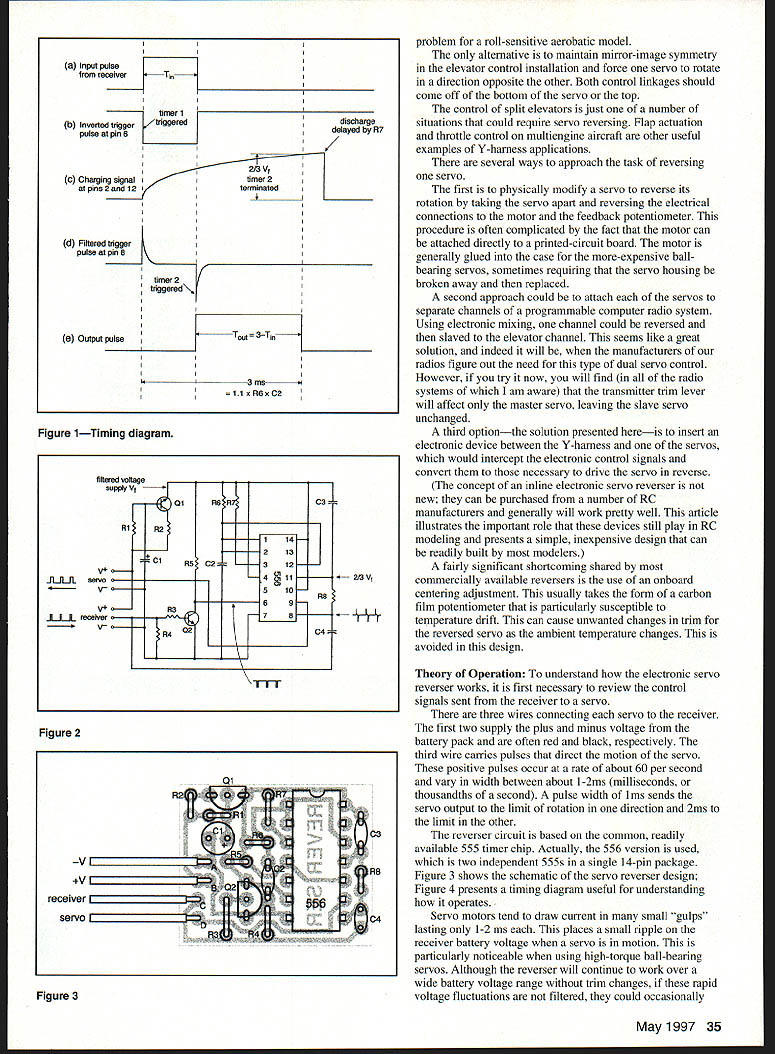
The reverser intercepts the signal pulses and generates a converted signal that drives the servo in the opposite direction. The circuit presented is based on the common 555 timer family; the dual 556 (two 555s in one 14-pin IC) is used.
Servo motors draw current in short bursts lasting 1–2 ms, which can cause rapid voltage ripple on the receiver battery. To prevent mechanical chatter and trim shifts caused by such voltage flutter, the design includes a filtered local supply using R1, C1, and Q1. R2 provides current limiting to protect Q1 from shorts.
Centering is implemented with a fixed-value R6 = 270 kΩ (1% metal-film) rather than an adjustable carbon pot. This fixed-value approach avoids temperature-related trim drift while providing reliable centering; modelers can still trim mechanically or via radio as usual.
Note: The schematic (not included here) shows component placement and the signal timing diagram referenced in the article. The design requires careful attention to transistor and polarized capacitor orientation.
Parts
Component list (from Table 1)
- 1 × 47 Ω resistor — Part number 271-1105
- 3 × 10 kΩ resistors — Part number 271-1335
- 4 × 47 kΩ resistors — Part number 271-1342
- 1 × 270 kΩ 1% metal-film resistor — (no Radio Shack number; obtain from electronics supplier)
- 1 × 470 pF ceramic disk capacitor — Part number 272-125
- 2 × 0.01 µF PC-mount capacitors — Part number 272-1065
- 1 × 22 µF radial-lead electrolytic capacitor — Part number 272-1026
- 2 × MPS2222A NPN transistors — Part number 276-2009
- 1 × 556 dual timer (two 555s in one package) — Part number 276-1728
Resistors and color codes (from Table 2)
- R1 — 10 kΩ — brown, black, orange*
- R2 — 47 kΩ — yellow, purple, black
- R3 — 10 kΩ — brown, black, orange
- R4 — 47 kΩ — yellow, purple, orange
- R5 — 47 kΩ — yellow, purple, orange
- R6 — 270 kΩ (1%) — red, purple, yellow
- R7 — 10 kΩ — brown, black, orange
- R8 — 47 kΩ — yellow, purple, orange
*The last resistor color band is gold for ±5% resistors.
Capacitors
- C1 — 22 µF electrolytic (observe polarity)
- C2 — 0.01 µF (labeled 103)
- C3 — 0.01 µF (labeled 103)
- C4 — 470 pF (labeled 471)
Transistors and IC
- Q1 — MPS2222A NPN
- Q2 — MPS2222A NPN
- IC1 — 556 dual timer
Connector pinout notes (from Table 3)
Wire color conventions vary by manufacturer. The table below summarizes common harness wiring. Points in the circuit are labeled A, B, C, D in the original schematic; when wiring input and output servo leads, attach wires according to your radio's color code.
- Airtronics: V+ = black / red; V− (center wire) = black; Signal = black
- JR: V+ = red (center wire); V− = brown; Signal = orange
- RCD / Hitec: V+ = red (center wire); V− = black; Signal = yellow
- Futaba: V+ = red (center wire); V− = black; Signal = white
Caution: Airtronics servo leads often use two black wires. Carefully identify which wire is the center (signal) wire before wiring.
Construction
An important goal was to use components available at retail electronics stores (e.g., Radio Shack). The 270 kΩ 1% metal-film resistor may need to be sourced from a specialist supplier.
A convenient method for making the PCB is Press-n-Peel blue film:
- Print or photocopy the PCB image onto the dull side of the film.
- Iron the film onto a copper-clad board (Radio Shack 276-1499) with a household iron or film-sealing iron. Tape one edge to the board and carefully peel small portions to check adhesion while experimenting with temperature.
- Etch the board in ferric chloride (Radio Shack 276-1535) for 30–60 minutes or until unwanted copper is removed. Note: the blank board is two-sided; copper will be removed from the back as well.
- Drill mounting holes with a #65 bit.
If you do not want to fabricate a PCB, contact the author for assistance or to purchase a board or kit.
Assembly:
- Insert components from the side opposite the copper pattern.
- Mount all resistors vertically.
- Observe polarity for electrolytic capacitor C1 and correct orientation for transistors and the 556 IC.
- Solder all joints, trim leads, and avoid solder bridges.
- Clean and brighten copper traces with fine steel wool or a ScotchBrite pad before soldering.
- Use quality resin-core electronics solder.
- Remove excess flux/resin with a solvent such as lacquer thinner and a short stiff brush.
Input/output leads can be made by cutting a servo extension cable in half. Attach the wires according to your radio's color code (see connector pinout notes).
IC1, C1, Q1, and Q2 orientation is critical. Capacitor C1 should have its positive lead marked.
Testing and Installation
Testing:
- Connect the reverser between the receiver (or one arm of a Y-harness) and the servo using standard servo leads.
- Apply power and operate the transmitter.
- Servos should center and respond normally.
- If chatter or poor centering occurs, recheck solder joints, component orientation, and the value of R6.
Installation:
- Mount the reverser in the model with double-sided foam tape and route servo leads to avoid sharp bends or chafing.
- Optionally slide the finished circuit into a short length of 1-inch heat-shrink tubing (do not overheat).
- You may attach a second set of output leads to points A, B, and C to create a built-in Y-harness.
- Wrap the finished circuit in 1/4-inch latex foam and secure with rubber bands to reduce engine vibration coupling.
The reverser provides a compact, inexpensive method to invert one servo relative to another without modifying servos or requiring extra radio channels.
Sources and Author Info
Press-n-Peel:
- All Electronics Corp., Van Nuys, CA 91411 — (818) 997-1806
Circuit boards and kits from the author:
- Circuit board available for $10 from the author
- Complete kit available for $15 from the author
- 270 kΩ resistor (only): send SASE to the author (no other charge)
For questions or additional information:
- Brent Dane
- Email: cbdane@pacbell.net
- Address: 678 Crane Ave., Livermore, CA 94550
Transcribed from original scans by AI. Minor OCR errors may remain.

