
The Seventh Iteration
John Hunton
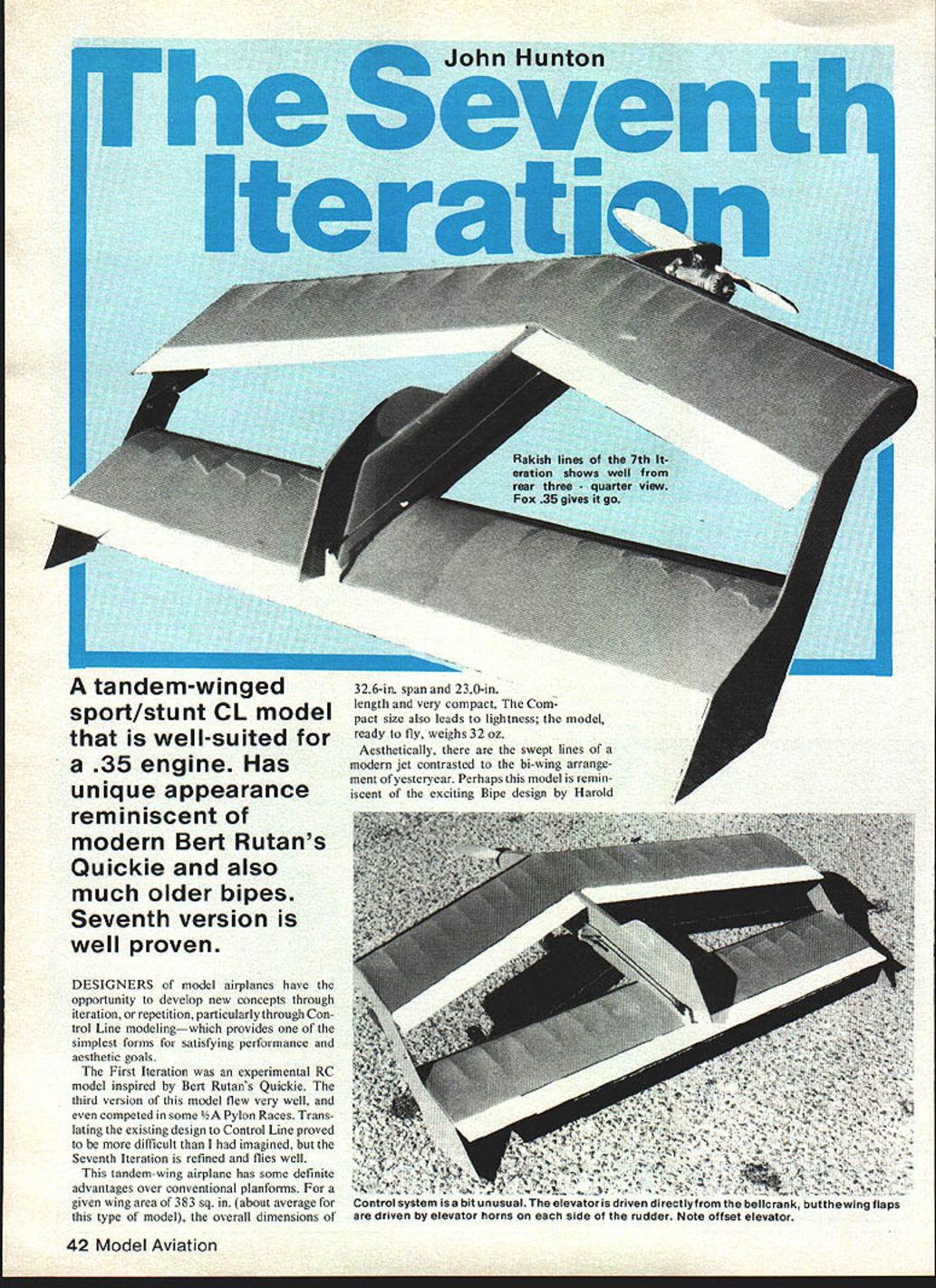
A tandem-winged sport/stunt control-line model that is well-suited for a .35 engine. It has a unique appearance reminiscent of Burt Rutan's Quickie and also evokes much older biplanes. The seventh version is well proven.
Designers of model airplanes have the opportunity to develop new concepts through iteration, or repetition, particularly through control-line modeling — which provides one of the simplest forms for satisfying performance and aesthetic goals.
The first iteration was an experimental RC model inspired by Burt Rutan's Quickie. The third version of this model flew very well, and even competed in some A- and B-class pylon races. Translating the existing design to control line proved to be more difficult than I had imagined, but the seventh iteration is refined and flies well.
This tandem-wing airplane has some definite advantages over conventional planforms. For a given wing area of 383 sq. in. (about average for this type of model), the overall dimensions of 32.6 in. span and 23.0 in. length are very compact. The compact size also leads to lightness; the model, ready to fly, weighs 32 oz.
Aesthetically, there are the swept lines of a modern jet contrasted with the bi-wing arrangement of yesteryear. Perhaps this model is reminiscent of the exciting biplane design by Harold DeBolt. It is definitely not run-of-the-mill in appearance, and it does perform well.
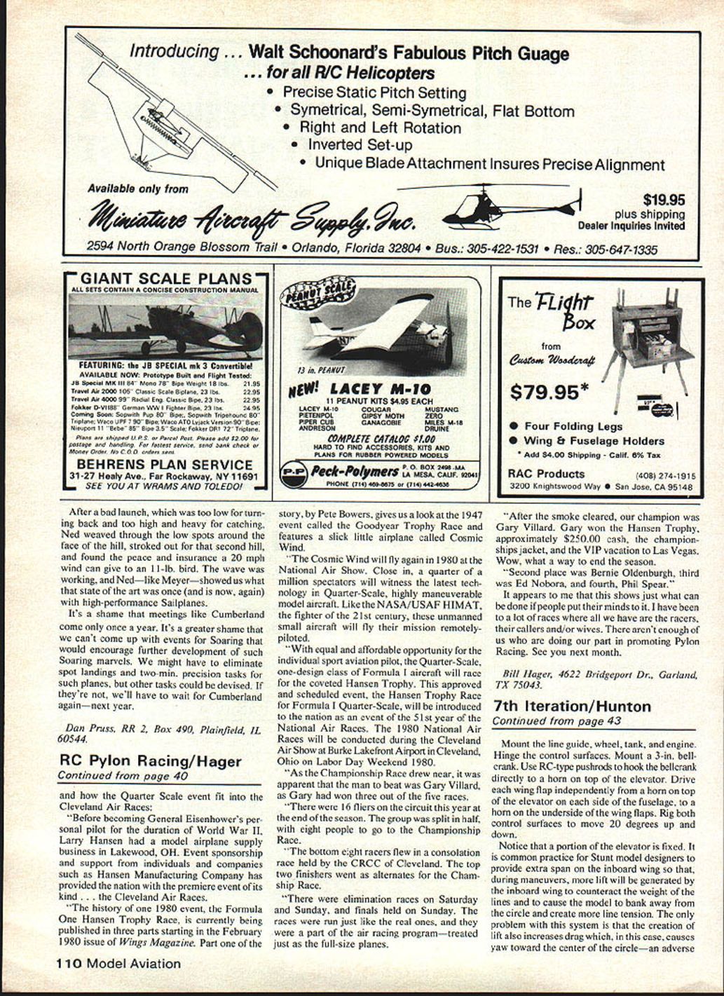
Construction
- Cut the fuselage from 1/8 x 3-in. sheet balsa. Install the 1/8 x 1/2-in. hardwood motor mounts, spaced to suit your engine. This model should perform well with any engine from .15 to .60, but keep the center-of-gravity (CG) where it is shown on the plan. Apply the 1/16-in. plywood motor mount doublers to each side of the fuselage.
- For most gluing, use aliphatic resin (white glue, such as Sigbond or Titebond), along with spots of cyanoacrylate (such as Hot Stuff or Jet) for rapid adhesion. Cyanoacrylate works fine in the presence of moisture, and white glue is economical.
- Install the bellcrank mount. Be certain to install the 3/32-in. dowels through the fuselage and bellcrank mount so that the mount will not pull out.
- Prepare wing ribs: ribs are identical for both wings, so they can be stack-sawn for quick building. Trim 1/16-in. off eight ribs for the center-section sheeting, which is applied to one side only.
- Leading and trailing edges: use stock shapes — 3/8 x 3/8-in. for the leading edge, and 1/4 x 1/8-in. (or a combination of shapes approximating this) for the trailing edge. Notch all leading and trailing edges 1/8-in. deep for the ribs.
- Butt-glue the foreplane (front wing) members together with cyanoacrylate at the proper angle. Assemble the wings and install a 1-1/2-oz. weight in the outboard of the foreplane. Cut a 1/8-in. slot in the foreplane leading edge and install the plywood reinforcing plate.
- Cut the tip plates and line guide from 1/8-in. plywood. Cut the wing flaps, elevator, fin and rudder from 1/8-in. firm sheet balsa. Sand everything smooth and to shape.
- Drill all required holes, then seal them with fuel-proof dope. Color-dope the complex shapes, and then cover the simple surfaces with heat-shrink covering, such as MonoKote or Coverite.
- Cut away the finish where surfaces join, insert the landing gear, then assemble everything with epoxy.
7th Iteration / Hunton
Continued from page 43
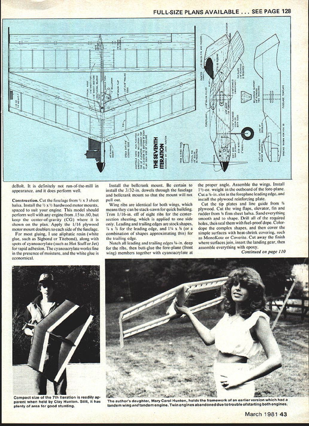
Mount the line guide, wheel, tank, and engine. Hinge the control surfaces. Mount a 3-in. bellcrank. Use RC-type pushrods to hook the bellcrank directly to a horn on top of the elevator. Drive each wing flap independently from a horn on top of the elevator on each side of the fuselage to a horn on the underside of the wing flaps. Rig both control surfaces to move 20 degrees up and 20 degrees down.
Notice that a portion of the elevator is fixed. It is common practice for stunt model designers to provide extra span on the inboard wing so that, during maneuvers, more lift will be generated by the inboard wing to counteract the weight of the lines and to cause the model to bank away from the circle and create more line tension. The only problem with this system is that the creation of lift also increases drag which, in this case, causes yaw toward the center of the circle—an adverse effect.
The seventh iteration, however, has a nearly full-span elevator. When control is applied, lift is generated by the elevator in the opposite direction of overall system lift. The negative lift is accompanied by drag which, this time, is on the outside of the model.
It is possible to trim this model to fly very true to the circle, and to fly with minimal yaw and roll through maneuvers. As you trim your model, you may want to add tail weight to increase control sensitivity.
Transcribed from original scans by AI. Minor OCR errors may remain.

