
Seville
Model aeronautics have undergone significant evolutionary changes through the years. Having to do with more reliable equipment, new materials, improved construction techniques and a lot of "guts" on the part of some individuals to depart from convention and negative attitudes, these changes have produced easy to build, excellent performing model aircraft with eye appeal.
The Seville is a new departure from convention. It proves, contrary to most attitudes, that a low-wing rudder-and-elevator sailplane is practical. Not only is the Seville practical, it is highly stable and has the good lines of a full-size aircraft. Its eye appeal is most dramatic when making a fly-by, as well as on the landing approach and touching down on the single wheel to roll to rest tail high. So setting aside convention and traditional attitudes, our mental struggle began to design a low-wing, hook-happy, winch-wanton-thermal ship.
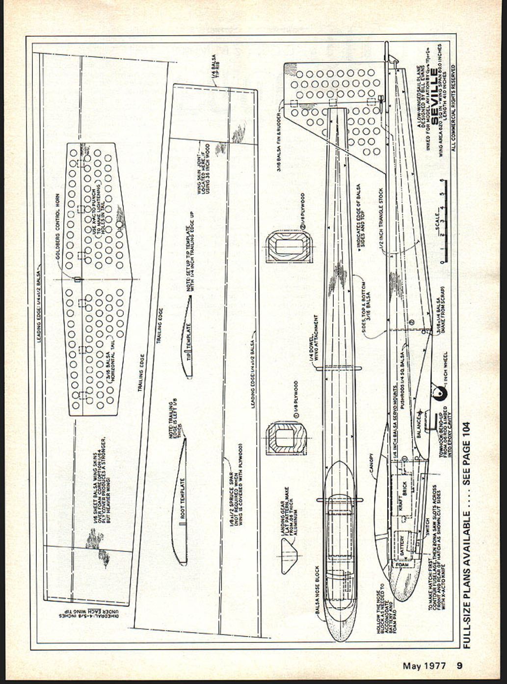
The wing airfoil, configuration, span, area and materials were the first consideration. A moderately thin flat-bottom airfoil was chosen to give good penetration and a fairly fast movement of air over the wing. The swept-back leading edge provides a bit of the needed dihedral (basically, each ten degrees of sweepback gives the effect of one degree of dihedral). To effect a wing loading of near 8 oz. per sq. ft., a root chord of 9½ in. and tip chord of 6 in. yielded an 80-in. span. The fully sheeted foam wing is easy to build and gives needed strength for winch launches. It can be sheeted with ply or balsa—the former requires no spar.
Though the Seville is a thermal ship in every respect, for the test flight I couldn't quite bring myself to high-start a new low-wing rudder-and-elevator design. So I chose a gentle slope located in the Simi Valley. The Seville was pushed off into a four-knot wind. The flight performance was remarkable. Not only did the Seville maintain altitude, it managed a beautiful climb to 1200 feet plus. The turns were a piece of cake, requiring a minimum of down-elevator when coming out of the turn.
Boyd Krueger, who shared watching the Seville's first flight, expressed disappointment that it flew contrary to his belief that low-wing, rudder-and-elevator-only "ships don't fly!" Boyd decided to compare the Seville's performance against a known model, so off into the air went his Hobie. To his surprise, the Seville kept pace with the Hobie. The Hobie maxed out at about 1500 feet; the Seville didn't get quite as high, just 1200 feet. After the 20-minute slope test flight we stretched out the high-start on a flat field. The Seville tracked straight up on a high-start launch that resulted in a seven-minute flight, in the cool 5 p.m. air.
At this time the four Sevilles built have turned in many one-hour thermal flights. Several more are under construction. One has been built using a .049 mounted in the nose for power assist.
From an appearance standpoint, most modelers who have seen it, view the Seville as something between a Schweizer 232 and a U-2; although I had no specific aircraft in mind when I designed it.
Then we considered the fuselage. To avoid splicing materials and not sacrifice stability, a good combination of nose and tail moments was worked out to permit using 36-in. stock for the fuse sides. The fairly large fuselage frontal area makes for greater ease in tracking through turns. A single wheel was incorporated to save wear and tear on the fuselage. The only place for the wheel was behind the C.G. By the way, the wheel position creates absolutely no difficulty with tow-line release.
The tail surface sizes make it possible to cut the necessary parts from two pieces of 3/16 x 4 x 36, and also provides for a satisfactory area ratio of the tail surfaces to wing of about 25%.
For your convenience foam wing cores cut for this Seville are available from Bill Evans, 19216 Calvert St., Reseda, CA 91335. Price is $10.00 which includes shipping (CA residents add 6% tax).
Construction
The following instructions are resequenced to minimize building time. Read them over before building to more completely understand them.
First you should decide on 1/16 balsa or 1/64 plywood for the wing sheeting. If 1/16 balsa sheeting is used a 1/8 X 1/2 spruce wing spar as shown on the plans must be employed. You may cut the spar groove in the foam cores by using a table saw with the saw blade raised 1/2 in. above the table top, or you may use a soldering gun with a properly bent wire tip as a depth gauge and balsa strips as guides.
Cement and pin 1/2 x 1/4 balsa strip to the leading edge of each wing panel, making sure that the leading edge is kept straight. Cut fuselage sides, top, bottom and formers from stock. Pin the fuselage top to a flat surface. Glue and pin the left fuselage side against the fuselage top. Glue and pin the 3/8 triangle stock against the left fuselage side and the fuselage top and repeat for the right side. Glue and pin fuselage formers in place. Glue and pin the 1/2 triangles to the bottom inside edges of the fuselage, front and rear. Glue and pin the fuselage bottom 3/8 sheet, front, and 3/16 rear. Rough cut nose block then pin and glue it to the fuselage.
Butt join and splice 1/16 balsa sheet to make four pieces that are each 40 in. long and taper from 10 in. on one end to 7 in. at the other. (Or 1/64" plywood may be used for wing sheeting as mentioned.) Apply contact cement to wing cores and wing sheeting (I suggest using a good water-base contact cement, such as Light-Dex). Let the cement dry per manufacturer's instructions. Bond sheeting to wing cores (be sure to use the foam wing cradles as a base on a flat surface to hold the 1/4 in. washout in each panel).
As you may know, washout is accomplished by raising the wing trailing edge at the wing tip, in this case 1/4 in., above the normal position without washout. The purpose of washout is to prevent excessive tip stall (falling off on one wing). Washout works like this: When an aircraft makes a turn, let's say left turn, the right wing moves faster than the left wing. The faster moving right wing creates more lift, which raises the right wing above the height of the left wing, causing a stall which usually results in the ship falling off the left. By washing out both wing tips an up aileron effect is produced which works against the increased lift which results in a much more smooth, flat turn.
Trim and sand wing panels and add 1/4 in. tip plates. Join wing panels using 5-min. epoxy and set dihedral by blocking each tip up 4 1/2 in.
Cut out the tail surfaces from 3/16 sheet, sand to shape, and cut lightening holes. (You can save on wood by butt-gluing a piece of 3/16 to the 4 x 3/16 sheet so as to cut the stab and elevator in one piece.)
Carve and sand fuselage to shape then cut bottom hatch for the radio compartment. The hatch is made by first making the front and rear cross-grain cuts. Using a razor saw make the length cuts on a right angle through the 1/8 triangle with an X-acto knife and a ruler for a straight edge.
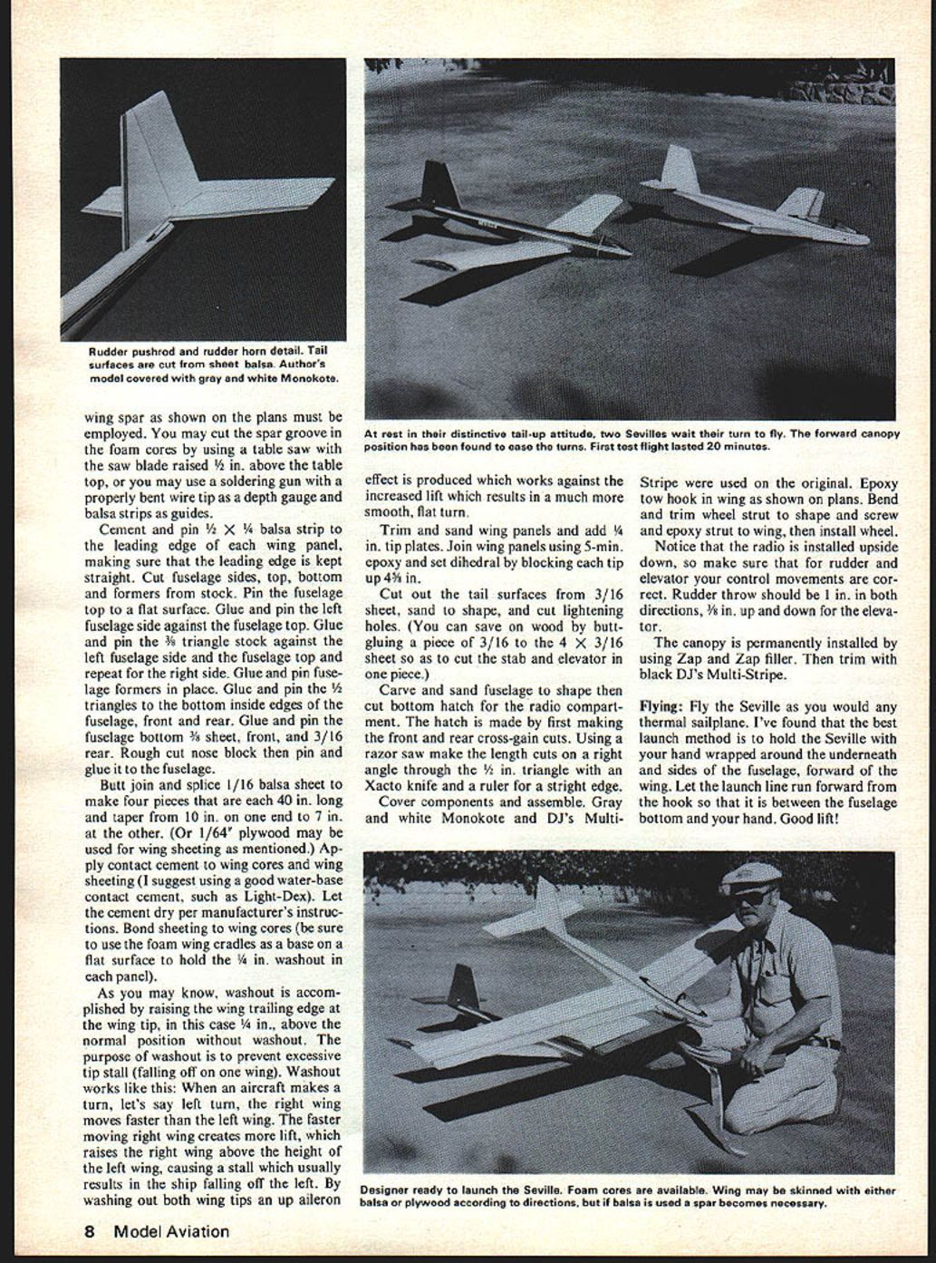
Cover components and assemble. Gray and white Monokote and DJ's Multi-Stripe were used on the original. Epoxy tow hook in wing as shown on plans. Bend and trim wheel strut to shape and screw and epoxy strut to wing, then install wheel.
Notice that the radio is installed upside down, so make sure that for rudder and elevator your control movements are correct. Rudder throw should be 1 in. in both directions, 1/8 in. up and down for the elevator.
The canopy is permanently installed by using Zap and Zap filler. Then trim with black DJ's Multi-Stripe.
Flying: Fly the Seville as you would any thermal sailplane. I've found that the best launch method is to hold the Seville with your hand wrapped around the underneath and sides of the fuselage, forward of the wing. Let the launch line run forward from the hook so that it is between the fuselage bottom and your hand. Good lift! Model aeronautics have undergone significant evolutionary changes through the years. With reliable equipment, new materials, improved construction techniques and a lot of guts on the part of some individuals who depart from conventional, negative attitudes, these changes have produced easy-to-build, excellent-performing model aircraft with eye appeal.
Seville is a new departure from convention and proves contrary to the attitude that low‑wing, rudder‑and‑elevator sailplanes are impractical. Seville is practical, highly stable and has the good lines of a full‑size aircraft. Its eye appeal is dramatic. On landing approach it touches down on a single wheel and rolls off tail‑high.
So, setting aside conventional, traditional attitudes, the mental struggle began in the design of a low‑wing, hook‑happy winch/wanton‑thermal ship. Wing airfoil, configuration, span, area and materials were the first considerations. A moderately thin, flat‑bottom airfoil was chosen to give good penetration and fairly fast movement of air over the wing. A swept‑back leading edge provides a bit of the needed dihedral; basically ten degrees of sweepback gives about 6° effective dihedral.
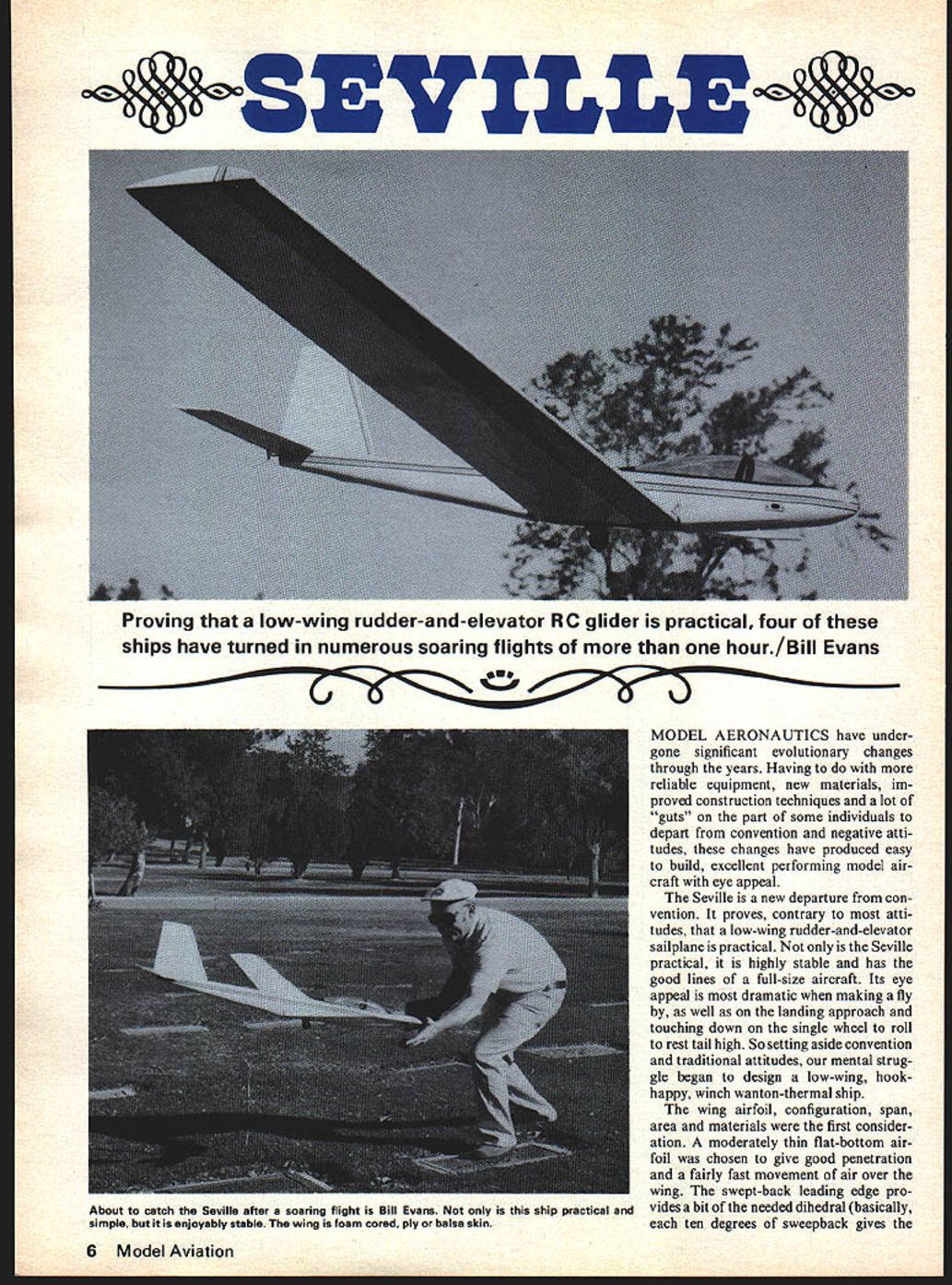
Proving a low‑wing, rudder‑and‑elevator RC glider practical, four ships have turned numerous soaring flights of one hour.
About catching Seville after a soaring flight: the ship is practical, simple and enjoyably stable. The wing is foam‑cored with plywood‑and‑balsa skin. The effect of the dihedral and the wing loading — near 8 oz per sq ft, with a root chord of 9 in. and a tip chord of 6 in. — yielded an 80‑inch span. The fully sheeted foam wing is easy to build and gives the needed strength; winch launches can be used. If sheeted with plywood/balsa the wing requires no spar.
Though Seville is primarily a thermal ship, I couldn't bring myself to high‑start a new low‑wing rudder‑and‑elevator design on the first trials. So I chose a gentle slope in Simi Valley. Seville was pushed off in a four‑knot wind. Flight performance was remarkable: Seville maintained altitude, managed a beautiful climb to over 1,200 feet and turns were a piece of cake, requiring minimum down‑elevator coming out of a turn. Boyd Krueger, who watched Seville's first flight, expressed his disappointment with his earlier belief that low‑wing, rudder‑and‑elevator ships don't fly. Boyd decided to compare Seville's performance against a known model, the Hobie. Surprise — Seville kept pace. The Hobie maxed out at about 1,500 feet; Seville reached about 1,200 feet.
After a 20‑minute slope test flight I stretched out a high‑start on a flat field. Seville tracked straight up on the high‑start launch and the result was a seven‑minute flight in cool late‑afternoon air. Four Sevilles built have produced one‑hour thermal flights. Several more are under construction; one was built using an .049 mounted in the nose for power assist.
From an appearance standpoint many modelers have seen Seville as something between a Schweizer 2‑32 and a U‑2, although no specific full‑size aircraft was in mind when designed. The fuselage was planned to avoid splicing materials and sacrificing stability. A good combination of nose and tail moment was worked out permitting the use of a 36‑in. stock fuselage side. The fairly large fuselage frontal area makes for greater ease in tracking through turns.
A single wheel is incorporated to save wear and tear to the fuselage. Placing the wheel behind the CG creates absolutely no difficulty with tow‑line release. Tail surface sizes make it possible to cut the necessary parts from two pieces of 3/16 x 4 x 36 balsa; this also provides a satisfactory area ratio of tail surfaces to wing — about 25%.
Foam wing cores for Seville are available from Bill Evans, 19216 Calvert St., Reseda, CA 91335. Price $10.00; includes shipping. California residents add 6% sales tax.
Construction The following instructions are sequenced to minimize building time. Read over the plans before building to completely understand the sequence.
First decide on wing sheeting: 1/16" balsa or 1/64" plywood. The original used 1/16" balsa sheeting. The spar is 1/8 x 1/2 spruce.
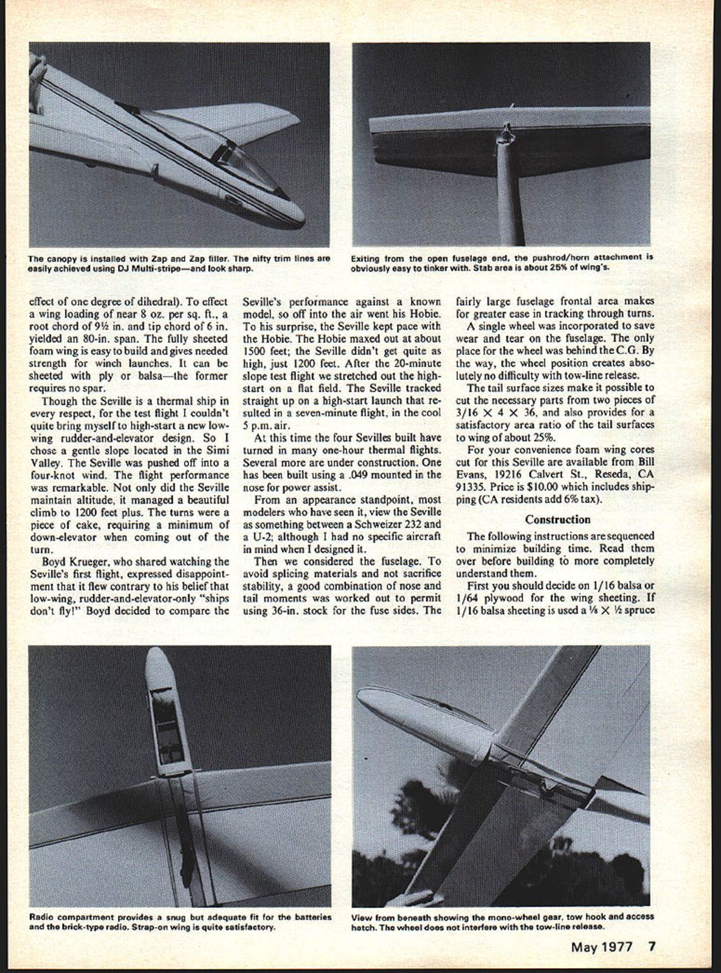
The canopy is permanently installed using Zap and Zap filler, then trimmed with black DJ's Multi‑Stripe for a neat appearance. An open fuselage end pushrod/horn attachment is easily achieved and looks sharp; it is obviously easy to tinker with.
The stabilizer area is about 26% of the wing area. The radio compartment provides a snug, adequate fit for batteries. The view beneath shows the mono‑wheel gear, tow‑hook access and the brick‑type radio installation. A strap‑on wing is quite satisfactory; note that the hatch wheel does not interfere with the tow‑line release.
The wing spar shown on the plans must be employed. You may cut the spar groove in the foam cores using a table saw with the blade set flush with the table top.
Transcribed from original scans by AI. Minor OCR errors may remain.

